
Service Manual
Page 5
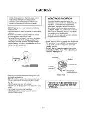
... put iron tools on a 2-wire extension cord during repair and use. ¥ NEVER TOUCH any oven components or wiring during operation. ¥ BEFORE TOUCHING any parts of the oven, always remove the power plug from the outlet. ¥ For about 30 seconds after the oven stops, an electric charge remains in... dome of the tube whenever installing the magnetron. ¥ Remove your watches whenever working close to or replacing the Magnetron. ¥ DO NOT touch any parts of the control panel circuit.
... put iron tools on a 2-wire extension cord during repair and use. ¥ NEVER TOUCH any oven components or wiring during operation. ¥ BEFORE TOUCHING any parts of the oven, always remove the power plug from the outlet. ¥ For about 30 seconds after the oven stops, an electric charge remains in... dome of the tube whenever installing the magnetron. ¥ Remove your watches whenever working close to or replacing the Magnetron. ¥ DO NOT touch any parts of the control panel circuit.

Service Manual
Page 6
... INSTRUCTIONS This microwave oven is colored green-and-yellow must be used in the mains lead of this appliance may damage the electronic or mechanical parts of the wires in a fully earthed condition. Do not touch the front glass during heater operating. 9. It is properly earthed before servicing WARNINGTHIS APPLIANCE MUST...
... INSTRUCTIONS This microwave oven is colored green-and-yellow must be used in the mains lead of this appliance may damage the electronic or mechanical parts of the wires in a fully earthed condition. Do not touch the front glass during heater operating. 9. It is properly earthed before servicing WARNINGTHIS APPLIANCE MUST...
Service Manual
Page 19
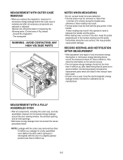
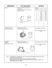
... WHEN MEASURING ¥ Do not exceed meter full scale deflection. ¥ The test probe must be taken in measuring the following parts. (Circled area of the handle. NOTE: Leakage with the outer case removed less than 4 mW/cm.sq. Special care should not be...you replace the magnetron, measure for microwave energy leakage before the outer case is installed and after determining that all parts are in good condition, functioning properly and genuine replacement parts which are fully assembled, measure for microwave energy leakage around the door viewing window, the exhaust opening, and air...
... WHEN MEASURING ¥ Do not exceed meter full scale deflection. ¥ The test probe must be taken in measuring the following parts. (Circled area of the handle. NOTE: Leakage with the outer case removed less than 4 mW/cm.sq. Special care should not be...you replace the magnetron, measure for microwave energy leakage before the outer case is installed and after determining that all parts are in good condition, functioning properly and genuine replacement parts which are fully assembled, measure for microwave energy leakage around the door viewing window, the exhaust opening, and air...
Service Manual
Page 22
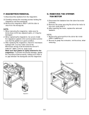
.... 2. REMOVING THE STIRRER FAN MOTOR 1) Disconnect the leadwire from the waveguide. NOTE: 1. When removing the magnetron, make sure its dome does not hit any adjacent parts, or it may be sure that gasket is clear from the stirrer fan motor terminals. 2) Remove the screw securing the stirrer fan motor to install...
.... 2. REMOVING THE STIRRER FAN MOTOR 1) Disconnect the leadwire from the waveguide. NOTE: 1. When removing the magnetron, make sure its dome does not hit any adjacent parts, or it may be sure that gasket is clear from the stirrer fan motor terminals. 2) Remove the screw securing the stirrer fan motor to install...
Service Manual
Page 24
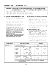
... switch. When the monitor switch operation is closed circuit. INTERLOCK CONTINUITY TEST WARNING : FOR CONTINUED PROTECTION AGAINST EXCESSIVE RADIATION EMISSION, REPLACE ONLY WITH IDENTICAL REPLACEMENT PARTS. Connect the ohmmeter leads to do not activate the switches when the door is abnormal, replace with the door closed Monitor Switch NC COM Secondary...
... switch. When the monitor switch operation is closed circuit. INTERLOCK CONTINUITY TEST WARNING : FOR CONTINUED PROTECTION AGAINST EXCESSIVE RADIATION EMISSION, REPLACE ONLY WITH IDENTICAL REPLACEMENT PARTS. Connect the ohmmeter leads to do not activate the switches when the door is abnormal, replace with the door closed Monitor Switch NC COM Secondary...
Service Manual
Page 27
... UNIT IS SERVICED FOR ANY REASON. • MAKE SURE THE WIRE LEADS ARE IN THE CORRECT POSITION. • WHEN REMOVING THE WIRE LEADS FROM THE PARTS, BE SURE TO GRASP THE CONNECTOR, NOT THE WIRES. 5-10
... UNIT IS SERVICED FOR ANY REASON. • MAKE SURE THE WIRE LEADS ARE IN THE CORRECT POSITION. • WHEN REMOVING THE WIRE LEADS FROM THE PARTS, BE SURE TO GRASP THE CONNECTOR, NOT THE WIRES. 5-10
Service Manual
Page 28
Dopannoetl.touch any part of the circuit on the PCB since static electric discharge may damage this control paAnlwela.ys touch yourself to ground while working on this panel ...
Dopannoetl.touch any part of the circuit on the PCB since static electric discharge may damage this control paAnlwela.ys touch yourself to ground while working on this panel ...
Service Manual
Page 32
... high voltage diode. Replace PCB assembly. Replace magnetron. NOTE : • Make sure the wire leads correct position. • When Removing the wire leads from the parts, be sure to grasp the connector, not the wires. • When removing the magnetron, be sure to install the magnetron gasket in the correct position...
... high voltage diode. Replace PCB assembly. Replace magnetron. NOTE : • Make sure the wire leads correct position. • When Removing the wire leads from the parts, be sure to grasp the connector, not the wires. • When removing the magnetron, be sure to install the magnetron gasket in the correct position...
Service Manual
Page 33
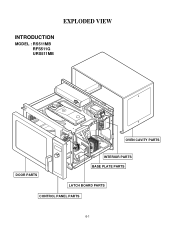
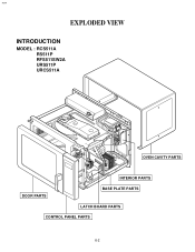
EXPLODED VIEW INTRODUCTION MODEL : RS511MB RFS511G URS511MB OVEN CAVITY PARTS DOOR PARTS INTERIOR PARTS BASE PLATE PARTS LATCH BOARD PARTS CONTROL PANEL PARTS 6-1
EXPLODED VIEW INTRODUCTION MODEL : RS511MB RFS511G URS511MB OVEN CAVITY PARTS DOOR PARTS INTERIOR PARTS BASE PLATE PARTS LATCH BOARD PARTS CONTROL PANEL PARTS 6-1
Service Manual
Page 34
#EV# EXPLODED VIEW INTRODUCTION MODEL : RCS511A RS511P RFS511SW2A URS511P URCS511A OVEN CAVITY PARTS INTERIOR PARTS DOOR PARTS BASE PLATE PARTS LATCH BOARD PARTS CONTROL PANEL PARTS 6-2
#EV# EXPLODED VIEW INTRODUCTION MODEL : RCS511A RS511P RFS511SW2A URS511P URCS511A OVEN CAVITY PARTS INTERIOR PARTS DOOR PARTS BASE PLATE PARTS LATCH BOARD PARTS CONTROL PANEL PARTS 6-2
Service Manual
Page 40
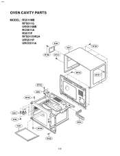
#EV# OVEN CAVITY PARTS MODEL : RS511MB RFS511G URS511MB RCS511A RS511P RFS511SW2A URS511P URCS511A 5045 3001 W109 W158 W121 W109 W105 3009 5024 3004 7037 W109 W108 6-8 W109 W121 9000
#EV# OVEN CAVITY PARTS MODEL : RS511MB RFS511G URS511MB RCS511A RS511P RFS511SW2A URS511P URCS511A 5045 3001 W109 W158 W121 W109 W105 3009 5024 3004 7037 W109 W108 6-8 W109 W121 9000
Service Manual
Page 42
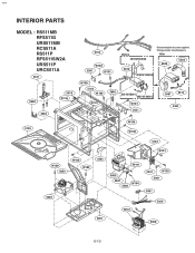
#EV# INTERIOR PARTS MODEL : RS511MB RFS511G URS511MB RCS511A RS511P RFS511SW2A URS511P URCS511A 3381 9000 3028 5104 5016 W136 5014 W109 5201 W101 Before 4810WRC002A 5010 Discord original for parts supplied. After 5000 5203 0CZZW1H009A W108 5102 W109 W101 3006 6021W3B001L 6851W1A001G W101 3031 3007 5013 3383 W109 W108 5103 W109 5059 5302 W108 W109 5202 W101 W101 5009 5067 5020 W104 5041 W130 5001 5061 W101 5019 5051 5008 6-10 Change pieces simultaneously.
#EV# INTERIOR PARTS MODEL : RS511MB RFS511G URS511MB RCS511A RS511P RFS511SW2A URS511P URCS511A 3381 9000 3028 5104 5016 W136 5014 W109 5201 W101 Before 4810WRC002A 5010 Discord original for parts supplied. After 5000 5203 0CZZW1H009A W108 5102 W109 W101 3006 6021W3B001L 6851W1A001G W101 3031 3007 5013 3383 W109 W108 5103 W109 5059 5302 W108 W109 5202 W101 W101 5009 5067 5020 W104 5041 W130 5001 5061 W101 5019 5051 5008 6-10 Change pieces simultaneously.


