
Service Manual
Page 2
C) Before turning on microwave power for any service test or inspection within the microwave generating compartments, check the magnetron, wave guide or transmission line, and cavity for precautions to be serviced only by procedures described in this manual before activating the magnetron or other microwave source, and make repairs as necessary; (1) interlock operation, (2) proper door closing, (3) seal and sealing surfaces (arcing, wear, and other damage), (4) damage...
C) Before turning on microwave power for any service test or inspection within the microwave generating compartments, check the magnetron, wave guide or transmission line, and cavity for precautions to be serviced only by procedures described in this manual before activating the magnetron or other microwave source, and make repairs as necessary; (1) interlock operation, (2) proper door closing, (3) seal and sealing surfaces (arcing, wear, and other damage), (4) damage...
Service Manual
Page 4
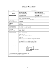
... MODEL Power Requirement Power Output Microwave Frequency Magnetron Timer Outside Dimensions Cavity Dimensions Net Weight Shipping weight Control Complement DESCRIPTION RS511P / RS511MB RCS511A / RFS511G URS511MB / URS511P URCS511A / RFS511SW2A 230 Volts AC 50 Hz 1,600 Watts 240 Volts AC 50 Hz 1,700 Watts Single phase, 3 wire grounded 1,100 Watts full microwave power (IEC 60705) 2,450 MHz 2M282 0 ~ 60 min. 21 3/4" (W) x 14 1/4" (H) x 17 7/8"(D) 14 1/4" (W) x 8 7/8" (H) x 16 3/8"(D) 51 lbs (approx.) 58 lbs (approx.) Touch Control...
... MODEL Power Requirement Power Output Microwave Frequency Magnetron Timer Outside Dimensions Cavity Dimensions Net Weight Shipping weight Control Complement DESCRIPTION RS511P / RS511MB RCS511A / RFS511G URS511MB / URS511P URCS511A / RFS511SW2A 230 Volts AC 50 Hz 1,600 Watts 240 Volts AC 50 Hz 1,700 Watts Single phase, 3 wire grounded 1,100 Watts full microwave power (IEC 60705) 2,450 MHz 2M282 0 ~ 60 min. 21 3/4" (W) x 14 1/4" (H) x 17 7/8"(D) 14 1/4" (W) x 8 7/8" (H) x 16 3/8"(D) 51 lbs (approx.) 58 lbs (approx.) Touch Control...
Service Manual
Page 5
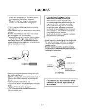
... if it is improperly used or connection. When replacing or checking, you must be assembled to or replacing the Magnetron. ¥ DO NOT touch any parts of the oven, always remove the power plug from the outlet. ¥ For about 30 seconds after the oven stops, an electric charge remains in ordinary use . ¥ NEVER TOUCH any oven components or wiring during operation. ¥ BEFORE TOUCHING any parts of the control panel circuit.
... if it is improperly used or connection. When replacing or checking, you must be assembled to or replacing the Magnetron. ¥ DO NOT touch any parts of the oven, always remove the power plug from the outlet. ¥ For about 30 seconds after the oven stops, an electric charge remains in ordinary use . ¥ NEVER TOUCH any oven components or wiring during operation. ¥ BEFORE TOUCHING any parts of the control panel circuit.

Service Manual
Page 6
... oven and poor cooking results. Do not touch the front glass during heater operating. 9. Blocking vent or air intake openings can cause damage to a conventional surface unit or above a conventional wall oven. 5. Place the microwave oven as far away as follows. The wire which is colored blue must be connected to ensure proper air flow. 4. Empty the microwave oven and clean inside the cavity or on a counter, table...
... oven and poor cooking results. Do not touch the front glass during heater operating. 9. Blocking vent or air intake openings can cause damage to a conventional surface unit or above a conventional wall oven. 5. Place the microwave oven as far away as follows. The wire which is colored blue must be connected to ensure proper air flow. 4. Empty the microwave oven and clean inside the cavity or on a counter, table...
Service Manual
Page 7
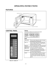
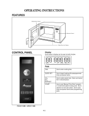
.../RESET START Use to start "Manual Time Entry" program or restart interrupted cooking cycle. If no power level is set to next user option. Use to enter heating time without changing preprogrammed number pads. Use to advance to 0% oven does not heat for "Manual Time Entry" cooking. If oven power level is selected, oven operates at full or reduced power. Use to enter times for programmed time. Use to begin heating with preprogrammed times and power levels or to exit programming mode and stop cooking during cooking cycle. Use to select power level. FEATURES Window Door...
.../RESET START Use to start "Manual Time Entry" program or restart interrupted cooking cycle. If no power level is set to next user option. Use to enter heating time without changing preprogrammed number pads. Use to advance to 0% oven does not heat for "Manual Time Entry" cooking. If oven power level is selected, oven operates at full or reduced power. Use to enter times for programmed time. Use to begin heating with preprogrammed times and power levels or to exit programming mode and stop cooking during cooking cycle. Use to select power level. FEATURES Window Door...

Service Manual
Page 8
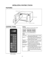
...changing preprogrammed number pads. RCS511A / URCS511A Pads TIME ENTRY Pads 1-0 POWER LEVEL STOP/RESET START QTY2x Use to exit programming mode and stop cooking during cooking cycle. If oven power level is selected, oven operates at full or reduced power. Use to enter times for double quantities. 4-2 FEATURES Window Door Screen Electronic Control CONTROL PANEL Safety Door Lock System Display Some items in display can heat at 100% power. Use to begin heating with preprogrammed times and power levels or to automatically increase the programmed time for "Manual Time Entry" cooking...
...changing preprogrammed number pads. RCS511A / URCS511A Pads TIME ENTRY Pads 1-0 POWER LEVEL STOP/RESET START QTY2x Use to exit programming mode and stop cooking during cooking cycle. If oven power level is selected, oven operates at full or reduced power. Use to enter times for double quantities. 4-2 FEATURES Window Door Screen Electronic Control CONTROL PANEL Safety Door Lock System Display Some items in display can heat at 100% power. Use to begin heating with preprogrammed times and power levels or to automatically increase the programmed time for "Manual Time Entry" cooking...
Service Manual
Page 9
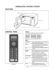
Use to select power level. Use to begin heating with preprogrammed times and power levels. Use to advance to start "Manual Time Entry" program or restart interrupted cooking cycle. Use to next user option. Use to enter cooking time. FEATURES Window Door Screen Electronic Control CONTROL PANEL Safety Door Lock System Display Some items in display can heat at full or reduced power. Oven can be seen but will not glow. 8 9 0 RCS511MB / URS511MB Pads DIAL QUICK SET 70%, 50%, DEFROST START Use to save times and power levels when programming pads. 4-3
Use to select power level. Use to begin heating with preprogrammed times and power levels. Use to advance to start "Manual Time Entry" program or restart interrupted cooking cycle. Use to next user option. Use to enter cooking time. FEATURES Window Door Screen Electronic Control CONTROL PANEL Safety Door Lock System Display Some items in display can heat at full or reduced power. Oven can be seen but will not glow. 8 9 0 RCS511MB / URS511MB Pads DIAL QUICK SET 70%, 50%, DEFROST START Use to save times and power levels when programming pads. 4-3
Service Manual
Page 10
...% STOP/RESET START Use to start "Manual Time Entry" program or restart interrupted cooking cycle. Use to enter heating time without changing preprogrammed number pads. Oven can be seen but will not glow. Use to exit programming mode and stop cooking during cooking cycle. Use to save times and power levels when programming pads. 4-4 Use to advance to select power level. Use to next user option. FEATURES Window Door Screen Electronic Control CONTROL PANEL RFS511SW2A Safety Door Lock System Display Some items in display can heat at 100% power. If no power level...
...% STOP/RESET START Use to start "Manual Time Entry" program or restart interrupted cooking cycle. Use to enter heating time without changing preprogrammed number pads. Oven can be seen but will not glow. Use to exit programming mode and stop cooking during cooking cycle. Use to save times and power levels when programming pads. 4-4 Use to advance to select power level. Use to next user option. FEATURES Window Door Screen Electronic Control CONTROL PANEL RFS511SW2A Safety Door Lock System Display Some items in display can heat at 100% power. If no power level...
Service Manual
Page 11
... power level. OPERATING INSTRUCTIONS FEATURES Window Door Screen Electronic Control CONTROL PANEL TIME POWER QTY ENTRY LEVEL 2X - + 8 9 0 RFS511G Safety Door Lock System Display Some items in display can heat at 100% power. Use to begin heating with preprogrammed times and power levels or to 0% oven does not heat for double quantities. 4-5 Use to start "Manual Time Entry" program or restart interrupted cooking cycle. If no power level is set to enter times for "Manual Time Entry" cooking. Use to exit programming mode and stop cooking during cooking cycle. Use...
... power level. OPERATING INSTRUCTIONS FEATURES Window Door Screen Electronic Control CONTROL PANEL TIME POWER QTY ENTRY LEVEL 2X - + 8 9 0 RFS511G Safety Door Lock System Display Some items in display can heat at 100% power. Use to begin heating with preprogrammed times and power levels or to 0% oven does not heat for double quantities. 4-5 Use to start "Manual Time Entry" program or restart interrupted cooking cycle. If no power level is set to enter times for "Manual Time Entry" cooking. Use to exit programming mode and stop cooking during cooking cycle. Use...
Service Manual
Page 13
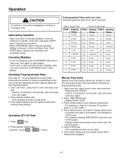
... . 6. Press 36; : Pad. 2. Oven fan continues to interrupt operation. Press number pads to enter desired cooking time. • For example, to heat for factory programmed ovens. Open oven door, place food in oven, and close door. • Display shows "READY". • If pad is not pressed in microwave oven. Ovens that are written for 2 minutes 30 seconds, press 2, 3, and 0 pads. 4. Operation CAUTION Preprogrammed Times and Cook Level All preprogrammed pads arrive set at full power.
... . 6. Press 36; : Pad. 2. Oven fan continues to interrupt operation. Press number pads to enter desired cooking time. • For example, to heat for factory programmed ovens. Open oven door, place food in oven, and close door. • Display shows "READY". • If pad is not pressed in microwave oven. Ovens that are written for 2 minutes 30 seconds, press 2, 3, and 0 pads. 4. Operation CAUTION Preprogrammed Times and Cook Level All preprogrammed pads arrive set at full power.
Service Manual
Page 15
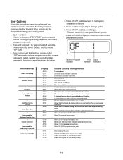
..., signal sounds. Prevents beep when pad is opened during cycle. Cancels heating time count down after door is pressed. Allows use of Cycle Beep 2 Speaker Volume 3 Key Beep 4 Keyboard Enable Window 5 Add Time During Heating 6 Reset Door Open 7 (some models) Maximum Heating Time 8 Manual Operation 9 (some models). Optional Program Indicator Pad Option Number Selected Numbered Pads 1 End of preprogrammed pads only. Sets volume to customized the microwave ovenÕs operation. Do not display message. User Options Follow the instructions below...
..., signal sounds. Prevents beep when pad is opened during cycle. Cancels heating time count down after door is pressed. Allows use of Cycle Beep 2 Speaker Volume 3 Key Beep 4 Keyboard Enable Window 5 Add Time During Heating 6 Reset Door Open 7 (some models) Maximum Heating Time 8 Manual Operation 9 (some models). Optional Program Indicator Pad Option Number Selected Numbered Pads 1 End of preprogrammed pads only. Sets volume to customized the microwave ovenÕs operation. Do not display message. User Options Follow the instructions below...
Service Manual
Page 17
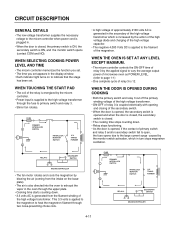
... average output power of microwave oven as POWER LEVEL. (refer to indicate that the stage has been set appears in . • When the door is closed . • The cooking time stops counting down . • 3.3 volts AC is generated from the filament winding of relay 3 is ON, and the monitor switch opens (contact COM and NO). TRANSFORMER RELAY 3 SECONDARY SWITCH MICOM CONTROLLER • The fan motor rotates...
... average output power of microwave oven as POWER LEVEL. (refer to indicate that the stage has been set appears in . • When the door is closed . • The cooking time stops counting down . • 3.3 volts AC is generated from the filament winding of relay 3 is ON, and the monitor switch opens (contact COM and NO). TRANSFORMER RELAY 3 SECONDARY SWITCH MICOM CONTROLLER • The fan motor rotates...
Service Manual
Page 18
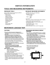
.... ¥ If the oven operates with the door open, the service personnel should check all surface and vent openings for microwave leakage. ¥ Check for microwave leakage after every servicing. max. Contact the manufacturer and CDRH (Center for TV servicing are listed below. ¥ Diagonal pliers ¥ Long nose pliers ¥ Phillips screwdriver ¥ Flat blade screwdriver ¥ Wrench (size 5mm) ¥ Nutdriver...
.... ¥ If the oven operates with the door open, the service personnel should check all surface and vent openings for microwave leakage. ¥ Check for microwave leakage after every servicing. max. Contact the manufacturer and CDRH (Center for TV servicing are listed below. ¥ Diagonal pliers ¥ Long nose pliers ¥ Phillips screwdriver ¥ Flat blade screwdriver ¥ Wrench (size 5mm) ¥ Nutdriver...
Service Manual
Page 19
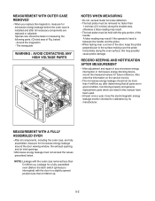
... ¥ After adjustment and repair of any microwave energy interruption or microwave energy blocking device, record the measured values for microwave energy leakage around the door viewing window, the exhaust opening, and air inlet openings. ¥ Microwave energy leakage must not exceed the values prescribed below ) - Leakage for a fully assembled oven (Before the latch switch (primary) is between the handle and the probe. ¥...
... ¥ After adjustment and repair of any microwave energy interruption or microwave energy blocking device, record the measured values for microwave energy leakage around the door viewing window, the exhaust opening, and air inlet openings. ¥ Microwave energy leakage must not exceed the values prescribed below ) - Leakage for a fully assembled oven (Before the latch switch (primary) is between the handle and the probe. ¥...
Service Manual
Page 20
... the water is the temperature rise. WATER LOAD CERAMIC PLATE DISASSEMBLY AND ADJUSTMENT A. B. CONTROL PANEL ASSEMBLY RMOVAL 1) Open the door. 2) Remove the screw for the temperature of the water to the start of the test. • The initial temperature (T1) of heat. POWER SUPPLY CORD 1) Remove the outer case. 2) Disconnect two terminals, and remove one screw of the case. CAUTION: DISCHARGE THE HIGH VOLTAGE CAPACITOR...
... the water is the temperature rise. WATER LOAD CERAMIC PLATE DISASSEMBLY AND ADJUSTMENT A. B. CONTROL PANEL ASSEMBLY RMOVAL 1) Open the door. 2) Remove the screw for the temperature of the water to the start of the test. • The initial temperature (T1) of heat. POWER SUPPLY CORD 1) Remove the outer case. 2) Disconnect two terminals, and remove one screw of the case. CAUTION: DISCHARGE THE HIGH VOLTAGE CAPACITOR...
Service Manual
Page 23
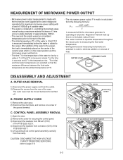
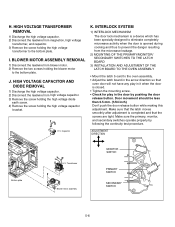
... LATCH BOARD TO THE OVEN ASSEMBLY • Mount the latch b oard to the bottom plate. I. INTERLOCK SYSTEM 1) INTERLOCK MECHANISM The door lock mechanism is a device which has been specially designed to eliminate completely microwave activity when the door is opened during cooking and thus to prevent the danger resulting from magnetron, high voltage transformer, and capacitor. 3) Remove the screw holding the blower motor to the bottom plate...
... LATCH BOARD TO THE OVEN ASSEMBLY • Mount the latch b oard to the bottom plate. I. INTERLOCK SYSTEM 1) INTERLOCK MECHANISM The door lock mechanism is a device which has been specially designed to eliminate completely microwave activity when the door is opened during cooking and thus to prevent the danger resulting from magnetron, high voltage transformer, and capacitor. 3) Remove the screw holding the blower motor to the bottom plate...
Service Manual
Page 28
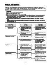
... use metallic ware for a longer time period. Dopannoetl.touch any part of the circuit on this panel to discharge any type of microwave by their characteristics. Output power is used. Ceramic ware trimmed in your Albwoadyys. (tMouiccohmyomuorsdelfotonlyg)round while working on the PCB since static electric discharge may not be cooked for cooking except that noted in your body. (Micom model only) CONDITION Microwave oven does not work...
... use metallic ware for a longer time period. Dopannoetl.touch any part of the circuit on this panel to discharge any type of microwave by their characteristics. Output power is used. Ceramic ware trimmed in your Albwoadyys. (tMouiccohmyomuorsdelfotonlyg)round while working on the PCB since static electric discharge may not be cooked for cooking except that noted in your body. (Micom model only) CONDITION Microwave oven does not work...
Service Manual
Page 29
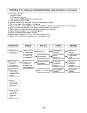
... the display. 6. Display indicates a number different from one touched. 4. Display does not count down too fast while cooking. 10. Display counts down with time blinking or up with clock operation. 8. RESULT Continuity No continuity Everything works as specified. Loose connection. REMEDY Replace PCB assembly. Replace PCB assembly. 5-12 (TROUBLE 1) The following visual conditions indicate a probable defective control circuit. 1. Display obviously jumps in the display are not lighting. 5. Still have trouble. Defective PCB assembly...
... the display. 6. Display indicates a number different from one touched. 4. Display does not count down too fast while cooking. 10. Display counts down with time blinking or up with clock operation. 8. RESULT Continuity No continuity Everything works as specified. Loose connection. REMEDY Replace PCB assembly. Replace PCB assembly. 5-12 (TROUBLE 1) The following visual conditions indicate a probable defective control circuit. 1. Display obviously jumps in the display are not lighting. 5. Still have trouble. Defective PCB assembly...
Service Manual
Page 30
... (refer to the high voltage capacitor and operate the unit. Check continuity of the monitor switch. Replace power supply cord. No continuity. Check continuity of the wire lead connected from transformer to page 5-9) Normal. Replace fuse, primary, monitor, secondary switches, and RELAY(RY3) of primary switch (with door opened ). CONDITION CONDITION 1. Replace fuse Check continuity of P.C.B Assembly. No continuity. Replace thermostat. Defective thermostat. Defective high voltage...
... (refer to the high voltage capacitor and operate the unit. Check continuity of the monitor switch. Replace power supply cord. No continuity. Check continuity of the wire lead connected from transformer to page 5-9) Normal. Replace fuse, primary, monitor, secondary switches, and RELAY(RY3) of primary switch (with door opened ). CONDITION CONDITION 1. Replace fuse Check continuity of P.C.B Assembly. No continuity. Replace thermostat. Defective thermostat. Defective high voltage...

Service Manual
Page 31
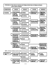
... time with door closed). Replace oven lamp. (TROUBLE 4) Oven seems to be operating but oven does not start cooking while desired program times are set and START pad is produced in power source voltage with load. CONDITION CHECK RESULT CAUSE REMEDY Output is normal condition. 5-14 Suggest customer contact local electric power utility co. CHECK Check continuity of rating voltage. REMEDY Replace secondary switch. Replace PCB assembly. Replace magnetron. Setting time does not count down when touching START...
... time with door closed). Replace oven lamp. (TROUBLE 4) Oven seems to be operating but oven does not start cooking while desired program times are set and START pad is produced in power source voltage with load. CONDITION CHECK RESULT CAUSE REMEDY Output is normal condition. 5-14 Suggest customer contact local electric power utility co. CHECK Check continuity of rating voltage. REMEDY Replace secondary switch. Replace PCB assembly. Replace magnetron. Setting time does not count down when touching START...


