
Service Manual
Page 1
R Microwave Oven Service Manual RRRRRCCCCCSSSSS1111100000PAMMMBPPPDASAAA RRFCSS1120MPPSSAA RRRFCFSSS111220SGSWW22AA RFS12MPSA RFS12G CAUTION BEFORE SERVICING THE UNIT, READ THE SAFETY PRECAUTIONS IN THIS MANUAL.
R Microwave Oven Service Manual RRRRRCCCCCSSSSS1111100000PAMMMBPPPDASAAA RRFCSS1120MPPSSAA RRRFCFSSS111220SGSWW22AA RFS12MPSA RFS12G CAUTION BEFORE SERVICING THE UNIT, READ THE SAFETY PRECAUTIONS IN THIS MANUAL.

Service Manual
Page 2
...procedures to assure continued safety operation and for proper alignment, integrity, and connections. C) Before turning on microwave power for any service test or inspection within the microwave generating compartments, check the magnetron, wave guide or transmission line, and cavity for precautions to be ... A) Do not operate or allow the oven to be serviced only by procedures described in this manual before activating the magnetron or other microwave source, and make repairs as necessary; (1) interlock operation, (2) proper door closing, (3) seal and sealing surfaces (arcing, wear, and ...
...procedures to assure continued safety operation and for proper alignment, integrity, and connections. C) Before turning on microwave power for any service test or inspection within the microwave generating compartments, check the magnetron, wave guide or transmission line, and cavity for precautions to be ... A) Do not operate or allow the oven to be serviced only by procedures described in this manual before activating the magnetron or other microwave source, and make repairs as necessary; (1) interlock operation, (2) proper door closing, (3) seal and sealing surfaces (arcing, wear, and ...
Service Manual
Page 4
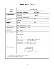
... Cavity Dimensions Cavity Dimensions Net Weight Net Weight Shipping weight Shipping weight CoCnotrnotrl oCl oCmomplepmlemenetnt DESCRIPTION RCS10MPA / RCS10MPSA / RCSD1E0SACRIPRTFISO12NMPSA / RFS12G RRCCS1S01S0WMP2AA / RCS10PRBCDSA10MPSA RFRSF1S21S2WM2PASA RFS12G 121020VVolotsltsAACC6600HHzz 1,15,05000WWaatttsts 1,800 ...oLwow a-apppproroxx..5500%%ooffFFuullllppoowweerr 202%0%(L(oLwow a-apppproroxx..2200%%ooffFFuullllppoowweerr NamNaempleaptelaLteocLaotcioantion This microwave oven is not recommended for buelt-in Installation. 1-1 1-1 SPECIFICATIONS AcIcteisssnoortierescommended for commercial use only...
... Cavity Dimensions Cavity Dimensions Net Weight Net Weight Shipping weight Shipping weight CoCnotrnotrl oCl oCmomplepmlemenetnt DESCRIPTION RCS10MPA / RCS10MPSA / RCSD1E0SACRIPRTFISO12NMPSA / RFS12G RRCCS1S01S0WMP2AA / RCS10PRBCDSA10MPSA RFRSF1S21S2WM2PASA RFS12G 121020VVolotsltsAACC6600HHzz 1,15,05000WWaatttsts 1,800 ...oLwow a-apppproroxx..5500%%ooffFFuullllppoowweerr 202%0%(L(oLwow a-apppproroxx..2200%%ooffFFuullllppoowweerr NamNaempleaptelaLteocLaotcioantion This microwave oven is not recommended for buelt-in Installation. 1-1 1-1 SPECIFICATIONS AcIcteisssnoortierescommended for commercial use only...

Service Manual
Page 5
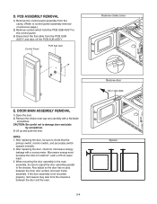
... COOLING FIN MAGNETRON CHASSIS GROUND MAGNETRON THE OVEN IS TO BE SERVICED ONLY BY PROPERLY QUALIFIED SERVICE PERSONNEL. 2-1 All input and output microwave connections, waveguide, flange, and gasket must discharge the high voltage capacitor by shorting across the two terminals with no load. ¥...it is properly installed around the dome of the tube whenever installing the magnetron. ¥ Remove your watches whenever working close to the microwave energy which may radiate from the outlet. ¥ For about 30 seconds after the oven stops, an electric charge remains in ordinary ...
... COOLING FIN MAGNETRON CHASSIS GROUND MAGNETRON THE OVEN IS TO BE SERVICED ONLY BY PROPERLY QUALIFIED SERVICE PERSONNEL. 2-1 All input and output microwave connections, waveguide, flange, and gasket must discharge the high voltage capacitor by shorting across the two terminals with no load. ¥...it is properly installed around the dome of the tube whenever installing the magnetron. ¥ Remove your watches whenever working close to the microwave energy which may radiate from the outlet. ¥ For about 30 seconds after the oven stops, an electric charge remains in ordinary ...
Service Manual
Page 6
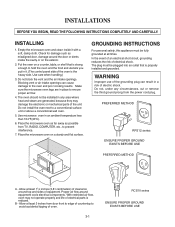
...cooking results. The plug must be fully grounded at least 11/2 inches (3.81 centimeters) of clearance around top and sides of equipment. Place the microwave oven on the exterior. 2. PREFERRED METHOD RFS12 series ENSURE PROPER GROUND EXISTS BEFORE USE AA AA AA BB PREFERRED METHOD A - In the event...the oven and the food and utensils you put in a risk of oven. 3-1 RCS10 series ENSURE PROPER GROUND EXISTS BEFORE USE Empty the microwave oven and clean inside the cavity or on a stardy and flat surface. Check for damage such as possible from the power cord plug. ...
...cooking results. The plug must be fully grounded at least 11/2 inches (3.81 centimeters) of clearance around top and sides of equipment. Place the microwave oven on the exterior. 2. PREFERRED METHOD RFS12 series ENSURE PROPER GROUND EXISTS BEFORE USE AA AA AA BB PREFERRED METHOD A - In the event...the oven and the food and utensils you put in a risk of oven. 3-1 RCS10 series ENSURE PROPER GROUND EXISTS BEFORE USE Empty the microwave oven and clean inside the cavity or on a stardy and flat surface. Check for damage such as possible from the power cord plug. ...
Service Manual
Page 14
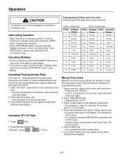
... pad once to stop oven, then again to clear display. • If oven door is not pressed in 30 seconds, open and time shows in microwave oven. Display continues to show countdown time. Oven stops heating and oven signal sounds when heating timing elapses.
... pad once to stop oven, then again to clear display. • If oven door is not pressed in 30 seconds, open and time shows in microwave oven. Display continues to show countdown time. Oven stops heating and oven signal sounds when heating timing elapses.

Service Manual
Page 16
..., okeoyrboisarodpdeisnaebdle,d.keyboard disabled) 2 minu2tems ainfteurteovsenadftoeorr iosvoepenneddo, okeryibsoaorpd edinsaebdle,dk. AllowAs lulosewosf 1m0anmuailntuimteesenotfryhaenadtpinregprtiomgrea.mmed pads. Press STOP/RESET pad or close oven door to customized the microwave ovenÕs operation. Sets volume to resume heating time countdown after door is opened Sets vEolluimmeintoatloews. Press and hold pad 2 for 24 hours every 7 days...
..., okeoyrboisarodpdeisnaebdle,d.keyboard disabled) 2 minu2tems ainfteurteovsenadftoeorr iosvoepenneddo, okeryibsoaorpd edinsaebdle,dk. AllowAs lulosewosf 1m0anmuailntuimteesenotfryhaenadtpinregprtiomgrea.mmed pads. Press STOP/RESET pad or close oven door to customized the microwave ovenÕs operation. Sets volume to resume heating time countdown after door is opened Sets vEolluimmeintoatloews. Press and hold pad 2 for 24 hours every 7 days...
Service Manual
Page 18
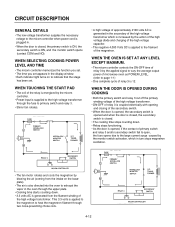
... to heat the magnetron filament through two noise-preventing choke coils. • A high voltage of approximately 2100 volts AC is generated in the secondary of microwave oven as POWER LEVEL. (refer to primary switch and realy 3. • Stirrer fan rotates. WHEN TOUCHING THE START PAD • The coil of the relay...
... to heat the magnetron filament through two noise-preventing choke coils. • A high voltage of approximately 2100 volts AC is generated in the secondary of microwave oven as POWER LEVEL. (refer to primary switch and realy 3. • Stirrer fan rotates. WHEN TOUCHING THE START PAD • The coil of the relay...
Service Manual
Page 19
...assembler of any certified oven unit found to have excessive emission levels at its maximum output. ¥ Measure the microwave radiation using and electromagnetic radiation monitor by the microwave oven should : - Tell the user not to assure correct result. ¥ When measuring the leakage, always ...brought into compliance. ¥ If the oven operates with the probe. ¥ Operate the oven at no cost to have a microwave emission level in .) ¥ Cylindrical and made of the excessive leakage. SERVICE INFORMATION TOOLS AND MEASURING INSTRUMENTS NECESSARY TOOLS Tools normally...
...assembler of any certified oven unit found to have excessive emission levels at its maximum output. ¥ Measure the microwave radiation using and electromagnetic radiation monitor by the microwave oven should : - Tell the user not to assure correct result. ¥ When measuring the leakage, always ...brought into compliance. ¥ If the oven operates with the probe. ¥ Operate the oven at no cost to have a microwave emission level in .) ¥ Cylindrical and made of the excessive leakage. SERVICE INFORMATION TOOLS AND MEASURING INSTRUMENTS NECESSARY TOOLS Tools normally...
Service Manual
Page 20
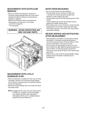
...in this may possibly cause probe damage. MEASUREMENT WITH OUTER CASE REMOVED ¥ When you replace the magnetron, measure for microwave energy leakage before the outer case is installed and after determining that all necessary components are replaced or adjusted. RECORD KEEPING ...reading may result if the operator's hand is interrupted) with the door in measuring the following parts. (Circled area of any microwave energy interruption or microwave energy blocking device, record the measured values for a fully assembled oven (Before the latch switch (primary) is between the handle...
...in this may possibly cause probe damage. MEASUREMENT WITH OUTER CASE REMOVED ¥ When you replace the magnetron, measure for microwave energy leakage before the outer case is installed and after determining that all necessary components are replaced or adjusted. RECORD KEEPING ...reading may result if the operator's hand is interrupted) with the door in measuring the following parts. (Circled area of any microwave energy interruption or microwave energy blocking device, record the measured values for a fully assembled oven (Before the latch switch (primary) is between the handle...
Service Manual
Page 21
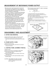
... moved backward to the vessel, the load is immediately placed on the center of the ceramic plate which is in the lowest position and the microwave power switched on. • The time T for securing the control panel. 3) Disconnect the leadwire from RELAY (RY3) of the PCB SUB ASS...of the PCB SUB ASS'Y. 5) Lift up and pull out control panel 5-3 MEASUREMENT OF MICROWAVE POWER OUTPUT • Microwave power output measurement is made with the microwave oven supplied at its rated voltage and operated at its maximum microwave power setting with a load of (1000±5) g of potable water. • ...
... moved backward to the vessel, the load is immediately placed on the center of the ceramic plate which is in the lowest position and the microwave power switched on. • The time T for securing the control panel. 3) Disconnect the leadwire from RELAY (RY3) of the PCB SUB ASS...of the PCB SUB ASS'Y. 5) Lift up and pull out control panel 5-3 MEASUREMENT OF MICROWAVE POWER OUTPUT • Microwave power output measurement is made with the microwave oven supplied at its rated voltage and operated at its maximum microwave power setting with a load of (1000±5) g of potable water. • ...
Service Manual
Page 22
... leak from the clearance between the inner door surface and oven frame assembly. After replacing the door, check for microwave energy leakage with a 275 ml water load) 3. NOTE: 1. When mounting the door assembly to the oven assembly, be sure to adjust the door assembly parallel... to damage door seal plate by screwdriver. 3) Lift up and push the door. Microwave energy must be sure to the control panel. 3) Disconnect the flat cable from the cavity. (Refer to control panel assembly removal on previous page.) 2) ...
... leak from the clearance between the inner door surface and oven frame assembly. After replacing the door, check for microwave energy leakage with a 275 ml water load) 3. NOTE: 1. When mounting the door assembly to the oven assembly, be sure to adjust the door assembly parallel... to damage door seal plate by screwdriver. 3) Lift up and push the door. Microwave energy must be sure to the control panel. 3) Disconnect the flat cable from the cavity. (Refer to control panel assembly removal on previous page.) 2) ...

Service Manual
Page 23
NOTE: 1. After replacing the magnetron, check for microwave leakage with a survey meter around the Microwave energy must be sure that gasket is in the correct position and be below the limit of 5 mW/cm2. (With a 275 ml. Make sure that ...the gasket is rigidly attached to the oven cavity ASS'Y 3) After repairing the motor, replace the removed leadwire. To prevent microwave leakage, tighten the mounting screws properly, making sure there is clear from the stirrer fan motor terminals. 2) Remove the screw securing the stirrer fan motor...
NOTE: 1. After replacing the magnetron, check for microwave leakage with a survey meter around the Microwave energy must be sure that gasket is in the correct position and be below the limit of 5 mW/cm2. (With a 275 ml. Make sure that ...the gasket is rigidly attached to the oven cavity ASS'Y 3) After repairing the motor, replace the removed leadwire. To prevent microwave leakage, tighten the mounting screws properly, making sure there is clear from the stirrer fan motor terminals. 2) Remove the screw securing the stirrer fan motor...
Service Manual
Page 28
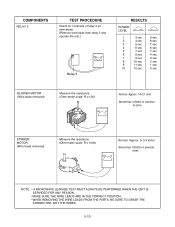
... or several ohm. STIRRER MOTOR (Wire leads removed) Measure the resistance. (Ohm-meter scale: R x 1000) Normal: Approx. 3~3.5 kohm Abnormal: Infinite or several K-ohm. NOTE : • A MICROWAVE LEAKAGE TEST MUST ALWAYS BE PERFORMED WHEN THE UNIT IS SERVICED FOR ANY REASON. • MAKE SURE THE WIRE LEADS ARE IN THE CORRECT POSITION...
... or several ohm. STIRRER MOTOR (Wire leads removed) Measure the resistance. (Ohm-meter scale: R x 1000) Normal: Approx. 3~3.5 kohm Abnormal: Infinite or several K-ohm. NOTE : • A MICROWAVE LEAKAGE TEST MUST ALWAYS BE PERFORMED WHEN THE UNIT IS SERVICED FOR ANY REASON. • MAKE SURE THE WIRE LEADS ARE IN THE CORRECT POSITION...
Service Manual
Page 29
...static charge built up in your body. (Micom model only) CONDITION CONDITION Microwave oven Midcrooewsanvoet wovoerkn. transformer. 5-11 Wfhroemn cthheescekipnagrttsheancdonthtiennuictyheocfkthceonstwiniutcithyewsitohr tohfethAeChpigluhgvroelmtaogveedtr.aTnosfdoormoethre, rdwisisceonmnaeyctreosnueltleinaad wire ... guide. Bheecckagrerofuulnodfitnhgebheigfohrevoclthaegcekcinirgcufoitr. Sparks occur. icrowave oven plug securely. Do not use the microwave oven. To do otherwise may result in a 5f.aDlsoenreotatdoiuncghoarndyapmaartgoefttoheyocuirrcmuiteotenr.the PCB since static...
...static charge built up in your body. (Micom model only) CONDITION CONDITION Microwave oven Midcrooewsanvoet wovoerkn. transformer. 5-11 Wfhroemn cthheescekipnagrttsheancdonthtiennuictyheocfkthceonstwiniutcithyewsitohr tohfethAeChpigluhgvroelmtaogveedtr.aTnosfdoormoethre, rdwisisceonmnaeyctreosnueltleinaad wire ... guide. Bheecckagrerofuulnodfitnhgebheigfohrevoclthaegcekcinirgcufoitr. Sparks occur. icrowave oven plug securely. Do not use the microwave oven. To do otherwise may result in a 5f.aDlsoenreotatdoiuncghoarndyapmaartgoefttoheyocuirrcmuiteotenr.the PCB since static...
Service Manual
Page 33
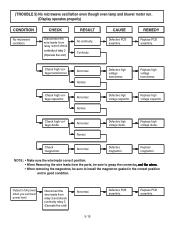
... lamp and blower motor run. (TROUBLE 5()DNisopmlaiycroopwearvaeteosspcrilolapteiornlye) ven though oven lamp and fan motor run. (Display operates properly) CONDITION CHECK RESULT CAUSE REMEDY CONDITION No microwave oscNilloatmioinc.rowave oscillation. Continuity. CB assembly. AAbbnnoorrmmaall NNoorrmmaall DDeefefecctitviveehhigighh vvooltlataggeeddioioddee. . ChCehcekck mmagangenterotrno.n. co(nOtipneuritayterethlaeyu3nit) (Operate the unit) Abnormal. No continuity. CAUSE Defective PCB DaesfseecmtivbelyP. Replace...
... lamp and blower motor run. (TROUBLE 5()DNisopmlaiycroopwearvaeteosspcrilolapteiornlye) ven though oven lamp and fan motor run. (Display operates properly) CONDITION CHECK RESULT CAUSE REMEDY CONDITION No microwave oscNilloatmioinc.rowave oscillation. Continuity. CB assembly. AAbbnnoorrmmaall NNoorrmmaall DDeefefecctitviveehhigighh vvooltlataggeeddioioddee. . ChCehcekck mmagangenterotrno.n. co(nOtipneuritayterethlaeyu3nit) (Operate the unit) Abnormal. No continuity. CAUSE Defective PCB DaesfseecmtivbelyP. Replace...


