User Manual
Page 4
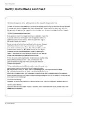
... filled with an exact replacement part by yourself (customer). Do not overload wall outlets. Pay particular attention to qualified service personnel. Overloaded wall outlets, loose or damaged wall outlets, extension cords, frayed power cords, or damaged or cracked wire insulation are dangerous. Periodically examine the cord of this appliance. Do not modify or extend the power cord. Do not install, remove, or reinstall the unit...
... filled with an exact replacement part by yourself (customer). Do not overload wall outlets. Pay particular attention to qualified service personnel. Overloaded wall outlets, loose or damaged wall outlets, extension cords, frayed power cords, or damaged or cracked wire insulation are dangerous. Periodically examine the cord of this appliance. Do not modify or extend the power cord. Do not install, remove, or reinstall the unit...
User Manual
Page 5
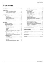
.../Off Timer Setup 21 Auto Off / Sleep Timer 21 Special Menu Options Key Lock 22 ISM (Image Sticking Minimization) Method . . . .22 Safety Instructions Low Power 23 XD Demo 23 Menu Rotation for Vertical Viewing 23 Screen Menu Options Auto Adjustment 24 Setting Picture Format 24 Screen Position 24 Manual Configure 25 Selecting VGA/XGA Mode 25 Screen Adjustments 25 Cinema Mode Setup 25 Luminance Noise Reduction 26 Initializing (Reset to original factory value) . . . . .26 Split Zoom 26 PIP (Picture-In-Picture)/Double...
.../Off Timer Setup 21 Auto Off / Sleep Timer 21 Special Menu Options Key Lock 22 ISM (Image Sticking Minimization) Method . . . .22 Safety Instructions Low Power 23 XD Demo 23 Menu Rotation for Vertical Viewing 23 Screen Menu Options Auto Adjustment 24 Setting Picture Format 24 Screen Position 24 Manual Configure 25 Selecting VGA/XGA Mode 25 Screen Adjustments 25 Cinema Mode Setup 25 Luminance Noise Reduction 26 Initializing (Reset to original factory value) . . . . .26 Split Zoom 26 PIP (Picture-In-Picture)/Double...

User Manual
Page 7
...INPUT SELECT VOLUME Main Power Button INPUT SELECT Button Sub Power Button Power Standby Indicator Illuminates red in standby mode. RS-232C INPUT (CONTROL/SERVICE) PORT Connect to these jacks. 7. DVD/DTV Input (Component 1-2) Connect a component video/audio device to the RS-232C port on DC power. EXTERNAL SPEAKER (8 ohm output) Connect to optional external speaker(s). * For further information, refer to the SVIDEO input. 8. Owner's Manual 7 Illuminates green when the Monitor is a simplified representation of a typical front panel. This is turned on. REMOTE CONTROL Connect...
...INPUT SELECT VOLUME Main Power Button INPUT SELECT Button Sub Power Button Power Standby Indicator Illuminates red in standby mode. RS-232C INPUT (CONTROL/SERVICE) PORT Connect to these jacks. 7. DVD/DTV Input (Component 1-2) Connect a component video/audio device to the RS-232C port on DC power. EXTERNAL SPEAKER (8 ohm output) Connect to optional external speaker(s). * For further information, refer to the SVIDEO input. 8. Owner's Manual 7 Illuminates green when the Monitor is a simplified representation of a typical front panel. This is turned on. REMOTE CONTROL Connect...

User Manual
Page 8
... Changes the picture format. (Refer to p.24) PIP/DW Switches the sub picture on or off . POWER SLEEP APC ARC PIP/DW SWAP MENU INPUT SELECT DASP SPLIT ZOOM WIN.POSITION SUB INPUT MUTE VOL OK VOL 1 2 3 4 5 6 7 8 9 0 WIN.SIZE POWER STOP PAUSE REW PLAY SKIP DVD FF OPEN/CLOSE POWER STOP VCR P/STILL REC REW PLAY FF INPUT SELECT Selects source: RGB, DVI, Component, Video or SVideo,mode. Introduction Remote Control Key Functions - NUMBER buttons DVD Control some video cassette...
... Changes the picture format. (Refer to p.24) PIP/DW Switches the sub picture on or off . POWER SLEEP APC ARC PIP/DW SWAP MENU INPUT SELECT DASP SPLIT ZOOM WIN.POSITION SUB INPUT MUTE VOL OK VOL 1 2 3 4 5 6 7 8 9 0 WIN.SIZE POWER STOP PAUSE REW PLAY SKIP DVD FF OPEN/CLOSE POWER STOP VCR P/STILL REC REW PLAY FF INPUT SELECT Selects source: RGB, DVI, Component, Video or SVideo,mode. Introduction Remote Control Key Functions - NUMBER buttons DVD Control some video cassette...

User Manual
Page 9
... to be mounted horizontally or vertically. If grounding methods are optional. The speakers shown are not possible, have a qualified electrician install a separate circuit breaker. ZOOM + Remote Control DVI-D Cable Power Cord D-sub 15 pin Cable Installation Instructions • The Monitor can be installed in various ways such as on a wall, or on a desktop etc. • The plasma display is missing, please contact the dealer where you connect the grounding...
... to be mounted horizontally or vertically. If grounding methods are optional. The speakers shown are not possible, have a qualified electrician install a separate circuit breaker. ZOOM + Remote Control DVI-D Cable Power Cord D-sub 15 pin Cable Installation Instructions • The Monitor can be installed in various ways such as on a wall, or on a desktop etc. • The plasma display is missing, please contact the dealer where you connect the grounding...

User Manual
Page 11
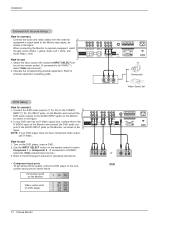
... button on cable box. 3. The TV cannot display TV programming unless a TV tuner device or cable TV converter box is used; Tune the TV channel to the same selected output channel on the remote control. (If connected to A/V INPUT 1, select Video input source) RGB OUTPUT COMPONENT INPUT 2 Y COMPONENT INPUT 1 PB PR VIDEO R L AUDIO S-VIDEO OUT (R) AUDIO (L) IN VIDEO R L/MONO MONITOR OUTPUT A/V INPUT AUDIO VIDEO S-VIDEO ( )R( ) ( )L( ) EXTERNAL SPEAKER VCR AC INPUT Do not connect to a cable TV service from the Cable Box's output jacks to the TV. - Cable Box Owner...
... button on cable box. 3. The TV cannot display TV programming unless a TV tuner device or cable TV converter box is used; Tune the TV channel to the same selected output channel on the remote control. (If connected to A/V INPUT 1, select Video input source) RGB OUTPUT COMPONENT INPUT 2 Y COMPONENT INPUT 1 PB PR VIDEO R L AUDIO S-VIDEO OUT (R) AUDIO (L) IN VIDEO R L/MONO MONITOR OUTPUT A/V INPUT AUDIO VIDEO S-VIDEO ( )R( ) ( )L( ) EXTERNAL SPEAKER VCR AC INPUT Do not connect to a cable TV service from the Cable Box's output jacks to the TV. - Cable Box Owner...
User Manual
Page 12
...If your DVD player does not have component video output, use 1. Installation External A/V Source Setup How to connect Connect the audio and video cables from the external equipment's output jacks to the component input ports as shown below. UT Y PB PR COMPONENT INPUT 1 R L R L/MONO MONITOR OUTPUT A/V INPUT ( )R( ) ( )L( ) EXTERNAL SPEAKER VIDEO AUDIO AUDIO VIDEO S-VIDEO puts to external equipment, match the jack colors (Video = yellow, Audio Left = white, and Audio Right = red). Component ports on the Monitor Y PB PR Video output ports on DVD player Y Pb Pr...
...If your DVD player does not have component video output, use 1. Installation External A/V Source Setup How to connect Connect the audio and video cables from the external equipment's output jacks to the component input ports as shown below. UT Y PB PR COMPONENT INPUT 1 R L R L/MONO MONITOR OUTPUT A/V INPUT ( )R( ) ( )L( ) EXTERNAL SPEAKER VIDEO AUDIO AUDIO VIDEO S-VIDEO puts to external equipment, match the jack colors (Video = yellow, Audio Left = white, and Audio Right = red). Component ports on the Monitor Y PB PR Video output ports on DVD player Y Pb Pr...
User Manual
Page 13
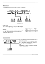
DTV Setup - Installation REMOTE CONTROL RS-232C INPUT (CONTROL/SERVICE) DVI INPUT AUDIO INPUT RGB INPUT RGB OUTPUT COMPONENT INPUT 2 Y COMPONENT INPUT 1 PB PR VIDEO R L AUDIO R L/MONO MONITOR OUTPUT A/V INPUT AUDIO VIDEO S-VIDEO ( )R( ) ( )L( EXTERNAL SPEAKER or or DVI-DTV OUTPUT (R) AUDIO (L) (R) AUDIO (L) RGB-DTV OUTPUT Digital Set-top Box B R (R) AUDIO (L) How to the owner's manual for video connections, depending on the remote control to the Monitor's MONITOR OUTPUT. Turn on the digital set-top box. (Refer to connect Use the Monitor's COMPONENT (Y, PB, ...
DTV Setup - Installation REMOTE CONTROL RS-232C INPUT (CONTROL/SERVICE) DVI INPUT AUDIO INPUT RGB INPUT RGB OUTPUT COMPONENT INPUT 2 Y COMPONENT INPUT 1 PB PR VIDEO R L AUDIO R L/MONO MONITOR OUTPUT A/V INPUT AUDIO VIDEO S-VIDEO ( )R( ) ( )L( EXTERNAL SPEAKER or or DVI-DTV OUTPUT (R) AUDIO (L) (R) AUDIO (L) RGB-DTV OUTPUT Digital Set-top Box B R (R) AUDIO (L) How to the owner's manual for video connections, depending on the remote control to the Monitor's MONITOR OUTPUT. Turn on the digital set-top box. (Refer to connect Use the Monitor's COMPONENT (Y, PB, ...
User Manual
Page 14
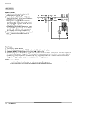
... INPUT or DVI (Digital Visual Interface) INPUT port for video connections, depending on your Monitor. If using a sound card, adjust the PC sound as required. Use INPUT SELECT on the PC does output analog and digital RGB simultaneously, set the Monitor to either RGB INPUT or DVI INPUT to display the PC on the Monitor. • If the graphic card on the remote control to connect 1. Check the image on the Monitor's screen for Horizontal and Vertical frequencies is present, change the PC mode...
... INPUT or DVI (Digital Visual Interface) INPUT port for video connections, depending on your Monitor. If using a sound card, adjust the PC sound as required. Use INPUT SELECT on the PC does output analog and digital RGB simultaneously, set the Monitor to either RGB INPUT or DVI INPUT to display the PC on the Monitor. • If the graphic card on the remote control to connect 1. Check the image on the Monitor's screen for Horizontal and Vertical frequencies is present, change the PC mode...
User Manual
Page 18
... skin color option. 1. PICTURE APC ACC Fleshtone Contrast 100 G Brightness 55 Color 55 Sharpness 60 Tint 0 Menu Prev. 18 Plasma Monitor Press the G button and then use D / E button to select Fleshtone. 3. Press the MENU button and then use D / E button to save. Press the G button and then use D / E button to select the desired picture option (Contrast, Brightness, Color, Sharpness, Tint). 3. Press the OK button to adjust for the color difference. 1. Manual Picture Control (APC set sRGB...
... skin color option. 1. PICTURE APC ACC Fleshtone Contrast 100 G Brightness 55 Color 55 Sharpness 60 Tint 0 Menu Prev. 18 Plasma Monitor Press the G button and then use D / E button to select Fleshtone. 3. Press the MENU button and then use D / E button to save. Press the G button and then use D / E button to select the desired picture option (Contrast, Brightness, Color, Sharpness, Tint). 3. Press the OK button to adjust for the color difference. 1. Manual Picture Control (APC set sRGB...
User Manual
Page 20
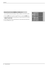
Press the G button and then use F / G button to select the desired sound option (Balance, Treble, Bass). 3. Press the G button and then use D / E button to make appropriate adjustments. 4. You can adjust sound options Balance, Treble, and Bass to save. SOUND DASP BBE AVL Balance 0G L R Treble 50 Bass 50 Menu Prev. 20 Plasma Monitor Press the OK button to the levels you prefer. 1. Operation Manual Sound Control (DASP set to select the SOUND menu. 2. Press the MENU button and then use D / E button to Off option) -
Press the G button and then use F / G button to select the desired sound option (Balance, Treble, Bass). 3. Press the G button and then use D / E button to make appropriate adjustments. 4. You can adjust sound options Balance, Treble, and Bass to save. SOUND DASP BBE AVL Balance 0G L R Treble 50 Bass 50 Menu Prev. 20 Plasma Monitor Press the OK button to the levels you prefer. 1. Operation Manual Sound Control (DASP set to select the SOUND menu. 2. Press the MENU button and then use D / E button to Off option) -

User Manual
Page 22
... Monitor's screen for prolonged periods will automatically invert the Monitor panel color every 30 minutes. 4. Operation Special Menu Options Key Lock - The Monitor can only be used to save . Press the OK button to prevent unauthorized viewing by locking out the front panel controls. - However, it can be set to remain on the screen. Press the MENU button and then use D / E button to Normal. • White wash White Wash removes permanent images from a PC/video game displayed...
... Monitor's screen for prolonged periods will automatically invert the Monitor panel color every 30 minutes. 4. Operation Special Menu Options Key Lock - The Monitor can only be used to save . Press the OK button to prevent unauthorized viewing by locking out the front panel controls. - However, it can be set to remain on the screen. Press the MENU button and then use D / E button to Normal. • White wash White Wash removes permanent images from a PC/video game displayed...
User Manual
Page 24
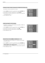
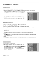
... view. • Zoom - G ARC Position Manual config Reset To set Menu Prev. Setting Picture Format - Use 4:3, or 16:9 for Monitor, Video, Component 480i sources. - Press the ARC button repeatedly to run Auto configure. • When Auto config. However, the top and bottom portions of the image is not available for RGB-DTV mode. - Press the G button and then use D / E button to select the SCREEN menu. 2. ARC Position G Manual config Reset D F G E Menu Prev. 24 Plasma Monitor Press the MENU button...
... view. • Zoom - G ARC Position Manual config Reset To set Menu Prev. Setting Picture Format - Use 4:3, or 16:9 for Monitor, Video, Component 480i sources. - Press the ARC button repeatedly to run Auto configure. • When Auto config. However, the top and bottom portions of the image is not available for RGB-DTV mode. - Press the G button and then use D / E button to select the SCREEN menu. 2. ARC Position G Manual config Reset D F G E Menu Prev. 24 Plasma Monitor Press the MENU button...

User Manual
Page 29
... selecting Set ID '0', every connected PDP set ID to specify a monitor ID number. - Error Acknowledgement [Command2][ ][Set ID][ ][NG][Data][x] * The Monitor transmits ACK (acknowledgement) based on transmission/receiving protocol. * [DATA]: To transmit command data. SPECIAL Language Key lock ISM Method Low power Set ID G 1 Demo OSD Rotate Menu Prev. Power k 02. PIP Position k 17. Picture Size j 31. Aspect Ratio k 04. If the data is controlled. OSD Select k 13. Input Select k 03. Volume Control...
... selecting Set ID '0', every connected PDP set ID to specify a monitor ID number. - Error Acknowledgement [Command2][ ][Set ID][ ][NG][Data][x] * The Monitor transmits ACK (acknowledgement) based on transmission/receiving protocol. * [DATA]: To transmit command data. SPECIAL Language Key lock ISM Method Low power Set ID G 1 Demo OSD Rotate Menu Prev. Power k 02. PIP Position k 17. Picture Size j 31. Aspect Ratio k 04. If the data is controlled. OSD Select k 13. Input Select k 03. Volume Control...

User Manual
Page 31
...:j) G To adjust the screen tint. You can also control the PIP/DW using the PIP/DW button on the remote control or in the Picture menu. Transmission [k][j][ ][Set ID][ ][Data][Cr] Data Red : 0 ~ Green : 64 • Refer to 'Real data mapping 2'. Sharpness (Command2:k) G To adjust the screen sharpness. OSD Select (Command2:l) G To select OSD (On Screen Display) on the monitor. Remote Control Lock Mode (Command2:m) G To lock the remote control and the front panel controls on /off 1: PIP 2: DW1...
...:j) G To adjust the screen tint. You can also control the PIP/DW using the PIP/DW button on the remote control or in the Picture menu. Transmission [k][j][ ][Set ID][ ][Data][Cr] Data Red : 0 ~ Green : 64 • Refer to 'Real data mapping 2'. Sharpness (Command2:k) G To adjust the screen sharpness. OSD Select (Command2:l) G To select OSD (On Screen Display) on the monitor. Remote Control Lock Mode (Command2:m) G To lock the remote control and the front panel controls on /off 1: PIP 2: DW1...

User Manual
Page 33
...][Data][x] External Control Device Setup 31. Auto Configure (Command2:u) G To adjust picture position and minimize image shaking automatically. It works only in Double Window mode. Acknowledgement [c][ ][Set ID][ ][OK][Data][x] Owner's Manual 33 Orbiter Pixel Setting (Command2:s) G To adjust pixel number in orbiter function. 26. Transmission [j][p][ ][Set ID][ ][Data][Cr] Data 0: Normal 1: White wash Acknowledgement 2: Orbiter 3: Inversion [p][ ][Set ID][ ][OK][Data][x] 27. Low Power (Command2:q) G To control the low power function...
...][Data][x] External Control Device Setup 31. Auto Configure (Command2:u) G To adjust picture position and minimize image shaking automatically. It works only in Double Window mode. Acknowledgement [c][ ][Set ID][ ][OK][Data][x] Owner's Manual 33 Orbiter Pixel Setting (Command2:s) G To adjust pixel number in orbiter function. 26. Transmission [j][p][ ][Set ID][ ][Data][Cr] Data 0: Normal 1: White wash Acknowledgement 2: Orbiter 3: Inversion [p][ ][Set ID][ ][OK][Data][x] 27. Low Power (Command2:q) G To control the low power function...
User Manual
Page 36
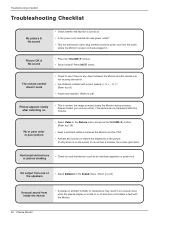
... Picture menu and press the VOLUME (G) button. (Refer to p.18) • Keep a sufficient distance between the Monitor and the VCR. • Activate any object between the Monitor and the remote control causing obstruction. • Are batteries installed with the Monitor. 36 Plasma Monitor Please contact your service center, if the picture has not appeared after switching on • This is normal, the image is turned on the screen...
... Picture menu and press the VOLUME (G) button. (Refer to p.18) • Keep a sufficient distance between the Monitor and the VCR. • Activate any object between the Monitor and the remote control causing obstruction. • Are batteries installed with the Monitor. 36 Plasma Monitor Please contact your service center, if the picture has not appeared after switching on • This is normal, the image is turned on the screen...
User Manual
Page 39
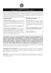
... limitations on the date of sale to the original consumer/end user. NEITHER THE MANUFACTURER NOR ITS U.S. This warranty gives you specific legal rights and you . This information will be repaired or replaced with the terms of Purchase. LIMITED WARRANTY Your LG Plasma Display Panel will be new or remanufactured. If repaired, parts used in your Product Registration Card or go to www...
... limitations on the date of sale to the original consumer/end user. NEITHER THE MANUFACTURER NOR ITS U.S. This warranty gives you specific legal rights and you . This information will be repaired or replaced with the terms of Purchase. LIMITED WARRANTY Your LG Plasma Display Panel will be new or remanufactured. If repaired, parts used in your Product Registration Card or go to www...
User Manual
Page 40
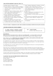
... installation, including incorrect or insufficient AC supply (please consult the owner's manual for power supply requirements) G installation or repair of antenna systems, cable converters, cable company supplied equipment, or other components in a video system G set-up or adjustment on the remote control. When calling for details. Parts and service in any product to the LGE Service Center. gence, improper maintenance or storage, or to acts of nature or other product G replacement...
... installation, including incorrect or insufficient AC supply (please consult the owner's manual for power supply requirements) G installation or repair of antenna systems, cable converters, cable company supplied equipment, or other components in a video system G set-up or adjustment on the remote control. When calling for details. Parts and service in any product to the LGE Service Center. gence, improper maintenance or storage, or to acts of nature or other product G replacement...
Brochure
Page 2
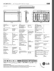
... User Adjustable AUDIO Mono/Stereo/MTS/SAP Bass/Treble/Balance Total Audio (Watts) Output (External Speakers) SPECIAL FEATURES Acoustic Noise Reduction Picture In Picture (PIP) Multilingual Menus 1 Level Mute Shock Absorbing Glass Damper RS-232 Control Discrete IR Controls Detachable AV Terminal Auto-Power On Discrete Power Off Last Source On Image Sticking Minimization Display/Mode Change (Vertical) Auto Off Aspect Ratio Control Split Zoom (Self Video Wall) Clock Timer Key Lock COMPATIBLE FORMATS NTSC, VGA, SVGA, XGA, SXGA HDTV...
... User Adjustable AUDIO Mono/Stereo/MTS/SAP Bass/Treble/Balance Total Audio (Watts) Output (External Speakers) SPECIAL FEATURES Acoustic Noise Reduction Picture In Picture (PIP) Multilingual Menus 1 Level Mute Shock Absorbing Glass Damper RS-232 Control Discrete IR Controls Detachable AV Terminal Auto-Power On Discrete Power Off Last Source On Image Sticking Minimization Display/Mode Change (Vertical) Auto Off Aspect Ratio Control Split Zoom (Self Video Wall) Clock Timer Key Lock COMPATIBLE FORMATS NTSC, VGA, SVGA, XGA, SXGA HDTV...


