

Owners Manual
Page 6
... improve its reliability. Wide angle range of noise could occur while the fans are operating and cooling the PDP. This means that your PC and video images simultaneously. Wide Screen The screen of 0.9 to 2.2 million cells. The PDP Manufacturing Process: Why minute colored dots may be exchanged or returned. 6 Plasma Monitor...
... improve its reliability. Wide angle range of noise could occur while the fans are operating and cooling the PDP. This means that your PC and video images simultaneously. Wide Screen The screen of 0.9 to 2.2 million cells. The PDP Manufacturing Process: Why minute colored dots may be exchanged or returned. 6 Plasma Monitor...

Owners Manual
Page 8
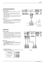
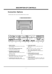
... INPUT (CONTROL/SERVICE) PORT Connect to the SVIDEO input. S-VIDEO INPUT SOCKETS Connect S-Video out from an external device to the appropriate input port. 4. VIDEO / AUDIO (L/MONO) INPUT SOCKETS Connect audio/video output from an S-VIDEO device to the RS-232C port on the Monitor. 2. POWER.... 3. REMOTE CONTROL Connect your monitor. COMPONENT INPUT/AUDIO INPUT JACKS Connect a component video/audio device to another monitor, connect RGB OUTPUT to these jacks. 8. NOTE: AUDIO INPUT of S-VIDEO is indicated on an AC power. Introduction Connection Options - RGB OUTPUT PORT You can...
... INPUT (CONTROL/SERVICE) PORT Connect to the SVIDEO input. S-VIDEO INPUT SOCKETS Connect S-Video out from an external device to the appropriate input port. 4. VIDEO / AUDIO (L/MONO) INPUT SOCKETS Connect audio/video output from an S-VIDEO device to the RS-232C port on the Monitor. 2. POWER.... 3. REMOTE CONTROL Connect your monitor. COMPONENT INPUT/AUDIO INPUT JACKS Connect a component video/audio device to another monitor, connect RGB OUTPUT to these jacks. 8. NOTE: AUDIO INPUT of S-VIDEO is indicated on an AC power. Introduction Connection Options - RGB OUTPUT PORT You can...
Owners Manual
Page 9
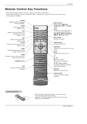
Under certain conditions such as necessary. NUMBER buttons DVD Control some video cassette recorders. MUTE Switches the sound on the monitor. - Adjusts menu settings. WIN.SIZE Adjusts the sub picture size. Press the key again as if ... POWER STOP PAUSE REW PLAY SKIP DVD FF OPEN/CLOSE POWER STOP VCR P/STILL REC REW PLAY FF INPUT SELECT Selects source: RGB, DVI, Component, Video, or S-Video mode. DASP To select the sound appropriate to your viewing program character: Flat, Music, Movie, Sports, SRS TSXT or Off (Refer to p.28) MENU...
Under certain conditions such as necessary. NUMBER buttons DVD Control some video cassette recorders. MUTE Switches the sound on the monitor. - Adjusts menu settings. WIN.SIZE Adjusts the sub picture size. Press the key again as if ... POWER STOP PAUSE REW PLAY SKIP DVD FF OPEN/CLOSE POWER STOP VCR P/STILL REC REW PLAY FF INPUT SELECT Selects source: RGB, DVI, Component, Video, or S-Video mode. DASP To select the sound appropriate to your viewing program character: Flat, Music, Movie, Sports, SRS TSXT or Off (Refer to p.28) MENU...

Owners Manual
Page 12
... visible on the screen. Connection Option 1. Y PB PR COMPONENT INPUT R L AUDIO INPUT S-VIDEO R L (MONO) AUDIO INPUT VIDEO INPUT ( )R( ) ( )L( ) EXTERNAL SPEAKER AC INPUT 12 Plasma Monitor (R) AUDIO (L) VIDEO TV VCR RF Cable Cable Box After subscribing to a cable TV service from the Cable Box's...- Select your local cable TV service provider(s). If the 4:3 picture format is improved; Connect the provided BNC-RCA adapter to VIDEO INPUT, select Video input source) 4. Typically a frozen still picture from the VCR's output jacks to the TV input jacks, as shown in ...
... visible on the screen. Connection Option 1. Y PB PR COMPONENT INPUT R L AUDIO INPUT S-VIDEO R L (MONO) AUDIO INPUT VIDEO INPUT ( )R( ) ( )L( ) EXTERNAL SPEAKER AC INPUT 12 Plasma Monitor (R) AUDIO (L) VIDEO TV VCR RF Cable Cable Box After subscribing to a cable TV service from the Cable Box's...- Select your local cable TV service provider(s). If the 4:3 picture format is improved; Connect the provided BNC-RCA adapter to VIDEO INPUT, select Video input source) 4. Typically a frozen still picture from the VCR's output jacks to the TV input jacks, as shown in ...
Owners Manual
Page 13
... jacks to the AUDIO INPUT jacks on DVD player Y Pb Pr Y B-Y R-Y Y Cb Cr Y PB PR B R (R) AUDIO (L) or S-VIDEO (R) AUDIO (L) DVD Owner's Manual 13 PONENT (Y, PB, PR) INPUT jacks on the Monitor and connect the DVD audio outputs to the AUDIO INPUT ...control to select Component. (If connected to use 1. Y PB PR COMPONENT INPUT R L AUDIO INPUT S-VIDEO R L (MONO) AUDIO INPUT VIDEO INPUT ( )R( ) ( )L( ) EXTERNAL SPEAKER AC INPUT How to S-VIDEO, select the S-Video external input source.) 3. How to the component input ports as shown in the figure. When connecting the ...
... jacks to the AUDIO INPUT jacks on DVD player Y Pb Pr Y B-Y R-Y Y Cb Cr Y PB PR B R (R) AUDIO (L) or S-VIDEO (R) AUDIO (L) DVD Owner's Manual 13 PONENT (Y, PB, PR) INPUT jacks on the Monitor and connect the DVD audio outputs to the AUDIO INPUT ...control to select Component. (If connected to use 1. Y PB PR COMPONENT INPUT R L AUDIO INPUT S-VIDEO R L (MONO) AUDIO INPUT VIDEO INPUT ( )R( ) ( )L( ) EXTERNAL SPEAKER AC INPUT How to S-VIDEO, select the S-Video external input source.) 3. How to the component input ports as shown in the figure. When connecting the ...

Owners Manual
Page 14
...Yes Yes RGB,DVI No Yes Yes Yes 14 Plasma Monitor Turn on the digital set-top box. (Refer to the owner's manual for video connections, depending on the remote control to select Component , RGB, or DVI source. Installation DTV Setup - REMOTE RS-232C INPUT CONTROL (...CONTROL/SERVICE) DVI INPUT AUDIO INPUT RGB INPUT RGB OUTPUT Y PB PR COMPONENT INPUT R L AUDIO INPUT S-VIDEO R L (MONO) AUDIO INPUT VIDEO INPUT or or DVI-DTV OUTPUT (R) AUDIO (L) (R) AUDIO (L) RGB-DTV OUTPUT B R (R) AUDIO (L) Digital Set-top Box How to use 1.
...Yes Yes RGB,DVI No Yes Yes Yes 14 Plasma Monitor Turn on the digital set-top box. (Refer to the owner's manual for video connections, depending on the remote control to select Component , RGB, or DVI source. Installation DTV Setup - REMOTE RS-232C INPUT CONTROL (...CONTROL/SERVICE) DVI INPUT AUDIO INPUT RGB INPUT RGB OUTPUT Y PB PR COMPONENT INPUT R L AUDIO INPUT S-VIDEO R L (MONO) AUDIO INPUT VIDEO INPUT or or DVI-DTV OUTPUT (R) AUDIO (L) (R) AUDIO (L) RGB-DTV OUTPUT B R (R) AUDIO (L) Digital Set-top Box How to use 1.

Owners Manual
Page 15
Use the Monitor's RGB INPUT or DVI (Digital Visual Interface) INPUT port for video connections, depending on your monitor. Check the image on the PC does output analog and digital RGB simultaneously, set to select RGB, or DVI source. 4. ...
Use the Monitor's RGB INPUT or DVI (Digital Visual Interface) INPUT port for video connections, depending on your monitor. Check the image on the PC does output analog and digital RGB simultaneously, set to select RGB, or DVI source. 4. ...
Owners Manual
Page 23
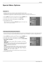
... remain on the screen if any button. • Orbiter Orbiter may be impossible to Normal. • White wash White Wash removes permanent images from a PC/video game displayed on the front panel is not necessary - This feature can be set up so that it was last set to clear entirely with...
... remain on the screen if any button. • Orbiter Orbiter may be impossible to Normal. • White wash White Wash removes permanent images from a PC/video game displayed on the front panel is not necessary - This feature can be set up so that it was last set to clear entirely with...

Owners Manual
Page 25
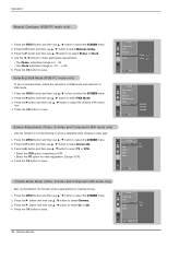
... to be shown on the screen for Component (480p,720p,1080i), DTV (480p,720p,1080i) sources. 1. SCREEN Auto config. Set every aspect ratio for Monitor, Video, Component 480i sources. - Press the G button and then use D / E button to select the SCREEN menu. 2. Screen Menu Options Operation Auto Adjustment - and Manual config...
... to be shown on the screen for Component (480p,720p,1080i), DTV (480p,720p,1080i) sources. 1. SCREEN Auto config. Set every aspect ratio for Monitor, Video, Component 480i sources. - Press the G button and then use D / E button to select the SCREEN menu. 2. Screen Menu Options Operation Auto Adjustment - and Manual config...
Owners Manual
Page 26
...G button and then use D / E button to select Screen adj.. 3. Press the OK button to correct jittering or picture instability while viewing a video tape. 1. SCREEN Screen adj. Press the MENU button and then use D / E button to select the SCREEN menu. 2. Press the OK button... and then use D / E button to select Cinema.. 3. ARC Position Manual config Reset VGA Mode G Menu Prev. 640x480 848x480 852x480 Screen Adjustments (Video, S-Video and Component 480i mode only) - Sets up the Monitor for the best picture appearance for other equipment. (Except VCR) 4. Press the G button and...
...G button and then use D / E button to select Screen adj.. 3. Press the OK button to correct jittering or picture instability while viewing a video tape. 1. SCREEN Screen adj. Press the MENU button and then use D / E button to select the SCREEN menu. 2. Press the OK button... and then use D / E button to select Cinema.. 3. ARC Position Manual config Reset VGA Mode G Menu Prev. 640x480 848x480 852x480 Screen Adjustments (Video, S-Video and Component 480i mode only) - Sets up the Monitor for the best picture appearance for other equipment. (Except VCR) 4. Press the G button and...

Owners Manual
Page 27
... select On or Off. 4. Press the MENU button and then use D / E button to select the SCREEN menu. 2. Screen Menu Options continued Operation Luminance Noise Reduction (Video, S-Video and Component 480i modes only) - Owner's Manual 27 Initializing (Reset to each function: Manual config., Position, Split zoom, PIP position and sub picture size for...
... select On or Off. 4. Press the MENU button and then use D / E button to select the SCREEN menu. 2. Screen Menu Options continued Operation Luminance Noise Reduction (Video, S-Video and Component 480i modes only) - Owner's Manual 27 Initializing (Reset to each function: Manual config., Position, Split zoom, PIP position and sub picture size for...
Owners Manual
Page 28
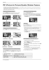
... and then use D / E button to select PIP Transparency . 3. Main Picture Source RGB or DVI Component 480p/720p/1080i Component 480i Video or S-Video Available Sub Picture Sources Component 480i, Video, or S-Video Video or S-Video Component 480p/720p/1080i, RGB, or DVI RGB, or DVI, Component 480p/720p/1080i 28 Plasma Monitor Use the F / G button to...
... and then use D / E button to select PIP Transparency . 3. Main Picture Source RGB or DVI Component 480p/720p/1080i Component 480i Video or S-Video Available Sub Picture Sources Component 480i, Video, or S-Video Video or S-Video Component 480p/720p/1080i, RGB, or DVI RGB, or DVI, Component 480p/720p/1080i 28 Plasma Monitor Use the F / G button to...
Owners Manual
Page 29
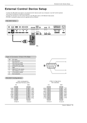
.... RS-232C Setup REMOTE RS-232C INPUT CONTROL (CONTROL/SERVICE) DVI INPUT AUDIO INPUT RGB INPUT RGB OUTPUT Y PB PR COMPONENT INPUT R L AUDIO INPUT S-VIDEO R L (MONO) AUDIO INPUT VIDEO INPUT ( )R( ) ( )L( ) EXTERNAL SPEAKER AC INPUT PC Type of the control device to send) 9 No Connection RS-232C Configurations 7-Wire Configurations (Standard RS-232C...
.... RS-232C Setup REMOTE RS-232C INPUT CONTROL (CONTROL/SERVICE) DVI INPUT AUDIO INPUT RGB INPUT RGB OUTPUT Y PB PR COMPONENT INPUT R L AUDIO INPUT S-VIDEO R L (MONO) AUDIO INPUT VIDEO INPUT ( )R( ) ( )L( ) EXTERNAL SPEAKER AC INPUT PC Type of the control device to send) 9 No Connection RS-232C Configurations 7-Wire Configurations (Standard RS-232C...
Owners Manual
Page 31
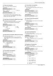
... source for the Monitor. You can also adjust mute using the MUTE button on remote control. Transmission [k][b][ ][Set ID][ ][Data][Cr] Data 0 : RGB 1 : DVI 2 : Component 3 : Video 4 : S-video Acknowledgement [b][ ][Set ID][ ][OK][Data][x] 03. Screen Mute (Command2:d) G To select screen mute on/off (Volume on (Volume off) 1 : Volume mute off . Transmission [k][e][ ][Set ID...
... source for the Monitor. You can also adjust mute using the MUTE button on remote control. Transmission [k][b][ ][Set ID][ ][Data][Cr] Data 0 : RGB 1 : DVI 2 : Component 3 : Video 4 : S-video Acknowledgement [b][ ][Set ID][ ][OK][Data][x] 03. Screen Mute (Command2:d) G To select screen mute on/off (Volume on (Volume off) 1 : Volume mute off . Transmission [k][e][ ][Set ID...
Owners Manual
Page 33
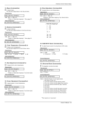
... ID][ ][Data][Cr] Data Min: 0 ~ Max: 3C • Refer to 'Real data mapping 3' as shown below. Transmission [k][y][ ][Set ID][ ][Data][Cr] Data 0: RGB 1: DVI 2: Component 3: Video 4: S-video Acknowledgement [y][ ][Set ID][ ][OK][Data][x] 25. 18. Red Adjustment (Command2:v) G To adjust red in PIP mode. Acknowledgement [t][ ][Set ID][ ][OK][Data][x] 20. Transmission [k][s][ ][Set ID...
... ID][ ][Data][Cr] Data Min: 0 ~ Max: 3C • Refer to 'Real data mapping 3' as shown below. Transmission [k][y][ ][Set ID][ ][Data][Cr] Data 0: RGB 1: DVI 2: Component 3: Video 4: S-video Acknowledgement [y][ ][Set ID][ ][OK][Data][x] 25. 18. Red Adjustment (Command2:v) G To adjust red in PIP mode. Acknowledgement [t][ ][Set ID][ ][OK][Data][x] 20. Transmission [k][s][ ][Set ID...

Owners Manual
Page 40
...organizations. G product sold and labeled as "as is, where is received, please use the carton and packaging from that unit in a video system G set-up or adjustment on the remote control. If a replacement unit is required, under these excluded circumstances shall be charged ...installation or repair of antenna systems, cable converters, cable company supplied equipment, or other components in returning the defective unit to the LG®Brand Service Center. CUSTOMER INTERACTIVE CENTER NUMBERS: To obtain customer assistance, product information or Dealer or Service locations Call 1-201-...
...organizations. G product sold and labeled as "as is, where is received, please use the carton and packaging from that unit in a video system G set-up or adjustment on the remote control. If a replacement unit is required, under these excluded circumstances shall be charged ...installation or repair of antenna systems, cable converters, cable company supplied equipment, or other components in returning the defective unit to the LG®Brand Service Center. CUSTOMER INTERACTIVE CENTER NUMBERS: To obtain customer assistance, product information or Dealer or Service locations Call 1-201-...
Service Manual
Page 5
...INPUT RGB INPUT RGB OUTPUT 1 2 3 4 Y PB PR COMPONENT INPUT R L AUDIO INPUT S-VIDEO 5 6 R L (MONO) AUDIO INPUT VIDEO INPUT 7 ( )R( ) ( )L( ) EXTERNAL SPEAKER AC INPUT 8 9 1. S-VIDEO INPUT SOCKETS Connect S-Video out from a PC to the appropriate input port. 4. EXTERNAL SPEAKER (8 ohm output) Connect to optional...voltage is worked by L(mono). 7. REMOTE CONTROL Connect your monitor. COMPONENT INPUT/AUDIO INPUT JACKS Connect a component video/audio device to another monitor, connect RGB OUTPUT to these jacks. 8. Connection panels shown may be somewhat different from...
...INPUT RGB INPUT RGB OUTPUT 1 2 3 4 Y PB PR COMPONENT INPUT R L AUDIO INPUT S-VIDEO 5 6 R L (MONO) AUDIO INPUT VIDEO INPUT 7 ( )R( ) ( )L( ) EXTERNAL SPEAKER AC INPUT 8 9 1. S-VIDEO INPUT SOCKETS Connect S-Video out from a PC to the appropriate input port. 4. EXTERNAL SPEAKER (8 ohm output) Connect to optional...voltage is worked by L(mono). 7. REMOTE CONTROL Connect your monitor. COMPONENT INPUT/AUDIO INPUT JACKS Connect a component video/audio device to another monitor, connect RGB OUTPUT to these jacks. 8. Connection panels shown may be somewhat different from...

Service Manual
Page 6
... your viewing program character: Flat, Music, Movie, Sports, SRS TSXT or Off. SWAP Exchanges main and sub picture images. NUMBER buttons DVD buttons Control some video cassette recorders. -6- W WIN.P VCR BUTTONS Control some DVD cassette recorders. WIN.POSITION Moves the sub picture. MUTE Switches the sound on or off . F / G (Volume button... POWER STOP PAUSE REW PLAY SKIP DVD FF OPEN/CLOSE POWER STOP VCR P/STILL REC REW PLAY FF INPUT SELECT Selects source: RGB, DVI, Component, Video, or S-Video mode. MENU Displays on the monitor. -
... your viewing program character: Flat, Music, Movie, Sports, SRS TSXT or Off. SWAP Exchanges main and sub picture images. NUMBER buttons DVD buttons Control some video cassette recorders. -6- W WIN.P VCR BUTTONS Control some DVD cassette recorders. WIN.POSITION Moves the sub picture. MUTE Switches the sound on or off . F / G (Volume button... POWER STOP PAUSE REW PLAY SKIP DVD FF OPEN/CLOSE POWER STOP VCR P/STILL REC REW PLAY FF INPUT SELECT Selects source: RGB, DVI, Component, Video, or S-Video mode. MENU Displays on the monitor. -

Service Manual
Page 20
Communication and HV sync? Comm. and HV sync good? TROUBLE SHOOTING GUIDE 5-2. Yes Is the Video Decoder No Are the Input voltage, IIC No VPC3230 good? Replace IC400 Replace IC - 20 - In case of does't display the screen into specific mode (1) ... from specific input mode (AV, Component, RGB, DVI). (2) Check follow ¯ Check the all input mode should become normality display. ¯ Check the Video(Main)/Data(Sub), Video(Main)/Video(Sub) should become normality display from the PIP mode or DW mode. (Re-Check it Swap) (3) Abnormal display in AV mode Is IC400...
Communication and HV sync? Comm. and HV sync good? TROUBLE SHOOTING GUIDE 5-2. Yes Is the Video Decoder No Are the Input voltage, IIC No VPC3230 good? Replace IC400 Replace IC - 20 - In case of does't display the screen into specific mode (1) ... from specific input mode (AV, Component, RGB, DVI). (2) Check follow ¯ Check the all input mode should become normality display. ¯ Check the Video(Main)/Data(Sub), Video(Main)/Video(Sub) should become normality display from the PIP mode or DW mode. (Re-Check it Swap) (3) Abnormal display in AV mode Is IC400...

Service Manual
Page 21
..., IIC No S2300 good? Are the Input voltage, IIC Comm. No Replace IC Replace IC Replace IC (5) Abnormal display in Component 480i mode Is the Video Decoder No Are the Input voltage, IIC No VPC3230 good? and HV sync good? TROUBLE SHOOTING GUIDE (4) Abnormal display in Component DTV mode(480p, 720p...
..., IIC No S2300 good? Are the Input voltage, IIC Comm. No Replace IC Replace IC Replace IC (5) Abnormal display in Component 480i mode Is the Video Decoder No Are the Input voltage, IIC No VPC3230 good? and HV sync good? TROUBLE SHOOTING GUIDE (4) Abnormal display in Component DTV mode(480p, 720p...


