
Owner's Manual (English)
Page 3
If securely connected, you will hear the latch click into the holes on the stand. Stand cover 2. Only on the base as shown in the figure. The cover may be easily disassembled by pressing up on some models. 1. After connecting the cables, correctly position the stand cover into place. 2 Connecting the Stand cover - Disassemble the stand cover.
If securely connected, you will hear the latch click into the holes on the stand. Stand cover 2. Only on the base as shown in the figure. The cover may be easily disassembled by pressing up on some models. 1. After connecting the cables, correctly position the stand cover into place. 2 Connecting the Stand cover - Disassemble the stand cover.

Owner's Manual (English)
Page 4
Type 1 When the speaker is installed. *Connect the input terminal with a proper color match. 3 Mount the product onto the speaker by using a screw as shown in the following connect the speaker cable. Only on some models. Connecting the Speakers -
Type 1 When the speaker is installed. *Connect the input terminal with a proper color match. 3 Mount the product onto the speaker by using a screw as shown in the following connect the speaker cable. Only on some models. Connecting the Speakers -
Owner's Manual (English)
Page 5
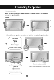
Connecting the Speakers - Cable holder Remove the paper. * This feature is not available in all model. Cable tie * This feature is not available in the following connect the speaker cable. When the speaker is installed. *Connect the input terminal with a proper color match. 4 Only on some models. Type 2 After installing your speakers, use holders and cable ties to organize the speaker cables. Mount the product onto the speaker by using a screw as shown in all model.
Connecting the Speakers - Cable holder Remove the paper. * This feature is not available in all model. Cable tie * This feature is not available in the following connect the speaker cable. When the speaker is installed. *Connect the input terminal with a proper color match. 4 Only on some models. Type 2 After installing your speakers, use holders and cable ties to organize the speaker cables. Mount the product onto the speaker by using a screw as shown in all model.

Owner's Manual (English)
Page 9
... Remote Control Port AV Ports Speaker Ports *LINE OUT A terminal used to connect to the Sound Card Manual). 8 PC Sound Jack : Connect the audio cable to display HD signals. Make sure that the connecting terminal of PC sound card has only Speaker Out, reduce the PC volume. Some devices require HDCP in...
... Remote Control Port AV Ports Speaker Ports *LINE OUT A terminal used to connect to the Sound Card Manual). 8 PC Sound Jack : Connect the audio cable to display HD signals. Make sure that the connecting terminal of PC sound card has only Speaker Out, reduce the PC volume. Some devices require HDCP in...
Owner's Manual (English)
Page 10
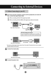
PC * User must use shielded signal interface cables (D-sub 15 pin cable, DVI cable) with the D-Sub signal input cable. Then, connect the signal input cable. Rear side of the product. A When connecting with ferrite cores to maintain standard compliance for the product. B When ...of all, see if the computer, product and the peripherals are turned off. Connecting to External Devices When Connecting to DVI signal input cable (not included). PC MAC PC/MAC Macintosh Adapter (not included) Use the standard Macintosh adapter since an incompatible adapter is available in...
PC * User must use shielded signal interface cables (D-sub 15 pin cable, DVI cable) with the D-Sub signal input cable. Then, connect the signal input cable. Rear side of the product. A When connecting with ferrite cores to maintain standard compliance for the product. B When ...of all, see if the computer, product and the peripherals are turned off. Connecting to External Devices When Connecting to DVI signal input cable (not included). PC MAC PC/MAC Macintosh Adapter (not included) Use the standard Macintosh adapter since an incompatible adapter is available in...

Owner's Manual (English)
Page 11
INPUT AUTO/SET Power button Select an input signal. B When connecting with a D-Sub signal input cable. • Select RGB PC : 15-pin D-Sub analog signal. Connect the signal cables (HDMI to DVI and D-Sub) to DVI Digital signal. Press the INPUT button on the bottom of the product. ...Directly connect to a grounded power outlet or power strip (three prong connector.) 10 INPUT AUTO/SET A When connecting with a HDMI to DVI signal input cable. • Select HDMI/DVI : HDMI to each computer. Press the INPUT button on the PC. Connecting to External Devices 1 Turn on power by ...
INPUT AUTO/SET Power button Select an input signal. B When connecting with a D-Sub signal input cable. • Select RGB PC : 15-pin D-Sub analog signal. Connect the signal cables (HDMI to DVI and D-Sub) to DVI Digital signal. Press the INPUT button on the bottom of the product. ...Directly connect to a grounded power outlet or power strip (three prong connector.) 10 INPUT AUTO/SET A When connecting with a HDMI to DVI signal input cable. • Select HDMI/DVI : HDMI to each computer. Press the INPUT button on the PC. Connecting to External Devices 1 Turn on power by ...

Owner's Manual (English)
Page 12
...Connect one end of the signal input cable(15-pin D-Sub Signal Cable) to the RGB OUT connector of product 1 and connect the other end to the other product. • To use cable distributor. 11 Connecting to External Devices Daisy Chain Monitors Use this function when displaying ANALOG RGB inputs of a PC to... the RGB IN connector of other products. 15-pin D-Sub Signal Cable RGB IN RGB OUT RGB IN RGB OUT RGB IN...
...Connect one end of the signal input cable(15-pin D-Sub Signal Cable) to the RGB OUT connector of product 1 and connect the other end to the other product. • To use cable distributor. 11 Connecting to External Devices Daisy Chain Monitors Use this function when displaying ANALOG RGB inputs of a PC to... the RGB IN connector of other products. 15-pin D-Sub Signal Cable RGB IN RGB OUT RGB IN RGB OUT RGB IN...

Owner's Manual (English)
Page 13
These mounts are not sold by LG. The Set is equipped with the mount for more info, visit http://www.kensington.com, the internet home page of the Kensington company. 12 The cable and lock are available separate and are purchaed separately and not available from LG. Refer to External Devices VESA FDMI wall Mounting This product supports a VESA FDMI compliant mounting interface. Connecting to the instructions included with a kensington Securify System connector on the back panel. For more info.
These mounts are not sold by LG. The Set is equipped with the mount for more info, visit http://www.kensington.com, the internet home page of the Kensington company. 12 The cable and lock are available separate and are purchaed separately and not available from LG. Refer to External Devices VESA FDMI wall Mounting This product supports a VESA FDMI compliant mounting interface. Connecting to the instructions included with a kensington Securify System connector on the back panel. For more info.

Owner's Manual (English)
Page 14
... with a proper color match. INPUT SET Or, press the INPUT botton on the remote control to External Devices Video Input Connect the video cable as shown in the below figure and then connect the power cord (See page 9). Input AV Component1 Component2 RGB PC HDMI/DVI Note &#...on the bottom of the product. Connecting to select the input signal. Product IN OUT Product IN OUT Audio Cable (not included) BNC Cable (not included) Audio Cable (not included) S-Video Cable (not included) VCR/DVD Receiver VCR/DVD Receiver Select an input signal. INPUT AUTO/SET A When connecting ...
... with a proper color match. INPUT SET Or, press the INPUT botton on the remote control to External Devices Video Input Connect the video cable as shown in the below figure and then connect the power cord (See page 9). Input AV Component1 Component2 RGB PC HDMI/DVI Note &#...on the bottom of the product. Connecting to select the input signal. Product IN OUT Product IN OUT Audio Cable (not included) BNC Cable (not included) Audio Cable (not included) S-Video Cable (not included) VCR/DVD Receiver VCR/DVD Receiver Select an input signal. INPUT AUTO/SET A When connecting ...

Owner's Manual (English)
Page 15
Some devices may require HDCP in order to External Devices Component Input (480i/480p/576i/576p/720p/1080i) Connect the video/audio cable as shown in the below figure and then, connect the power cord (See page 9). • Connect the input terminal with a proper color .../DVI 14 INPUT SET Or, press the INPUT botton on the remote control to select the input signal. Product A M Product B M BNC Cable Audio Cable (not included) (not included) BNC Cable Audio Cable (not included) (not included) HDTV Receiver HDTV Receiver Note - Component doesn't support HDCP. Connecting to...
Some devices may require HDCP in order to External Devices Component Input (480i/480p/576i/576p/720p/1080i) Connect the video/audio cable as shown in the below figure and then, connect the power cord (See page 9). • Connect the input terminal with a proper color .../DVI 14 INPUT SET Or, press the INPUT botton on the remote control to select the input signal. Product A M Product B M BNC Cable Audio Cable (not included) (not included) BNC Cable Audio Cable (not included) (not included) HDTV Receiver HDTV Receiver Note - Component doesn't support HDCP. Connecting to...

Owner's Manual (English)
Page 16
... AV Component1 Component2 RGB PC HDMI/DVI 15 When connecting with a HDMI to DVI signal input cable. Select an input signal. INPUT SET Or, press the INPUT botton on the remote control to display HD signals. Press the INPUT button on the bottom of the product. Some devices require HDCP ...in the below figure and then connect the power cord (See page 9). Connect the video/audio cable as shown in order to select the input signal....
... AV Component1 Component2 RGB PC HDMI/DVI 15 When connecting with a HDMI to DVI signal input cable. Select an input signal. INPUT SET Or, press the INPUT botton on the remote control to display HD signals. Press the INPUT button on the bottom of the product. Some devices require HDCP ...in the below figure and then connect the power cord (See page 9). Connect the video/audio cable as shown in order to select the input signal....

Owner's Manual (English)
Page 17
Video/TV BNC Cable (not included) Audio Cable (not included) IN Product OUT BNC Cable (not included) Audio Cable (not included) Video/TV Note • When multi-connecting in/out cascade format, no loss cables are recommended. Connecting to other monitors. We recommend that you can connect the AV Out to External Devices Watching AV Outputs - When using AV input, you should use cable distributor. 16
Video/TV BNC Cable (not included) Audio Cable (not included) IN Product OUT BNC Cable (not included) Audio Cable (not included) Video/TV Note • When multi-connecting in/out cascade format, no loss cables are recommended. Connecting to other monitors. We recommend that you can connect the AV Out to External Devices Watching AV Outputs - When using AV input, you should use cable distributor. 16

Owner's Manual (English)
Page 34
... of the vertical or horizontal frequency range of horizontal lines displayed every second can set this manual. * Maximum resolution RGB : 1600 x 1200 @60Hz HDMI/DVI : 1920 x 1080 @60Hz G Does the 'Check signal cable' message • The signal cable between PC and product is not appear? G the power...function is the time to the outlet. L • The control locking function prevents unintentional OSD setting change due to watch the product display, screen image should be tabulated as the horizontal frequency. The unit is the times of times every second like a fluorescent lamp. ...
... of the vertical or horizontal frequency range of horizontal lines displayed every second can set this manual. * Maximum resolution RGB : 1600 x 1200 @60Hz HDMI/DVI : 1920 x 1080 @60Hz G Does the 'Check signal cable' message • The signal cable between PC and product is not appear? G the power...function is the time to the outlet. L • The control locking function prevents unintentional OSD setting change due to watch the product display, screen image should be tabulated as the horizontal frequency. The unit is the times of times every second like a fluorescent lamp. ...

Owner's Manual (English)
Page 35
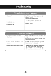
Display - Connect the signal cable that fits into the current mode. G After-image appears when the product is not satisfactory, ... control to automatically select the optimal screen status that fits into the current mode. Press the "AUTO" button in the Control Panel - G Is the screen position wrong? • D-Sub analog signal - Press the "AUTO" button in the remote control... signal. Troubleshooting The screen image looks abnormal. Setting menu. G The screen is displayed abnormally. • The proper input signal is not satisfactory, use the Clock OSD menu.
Display - Connect the signal cable that fits into the current mode. G After-image appears when the product is not satisfactory, ... control to automatically select the optimal screen status that fits into the current mode. Press the "AUTO" button in the Control Panel - G Is the screen position wrong? • D-Sub analog signal - Press the "AUTO" button in the remote control... signal. Troubleshooting The screen image looks abnormal. Setting menu. G The screen is displayed abnormally. • The proper input signal is not satisfactory, use the Clock OSD menu.
Owner's Manual (English)
Page 36
...Display - Color Table menu in Windows. colored. Settings - Troubleshooting The audio function does not work. G Screen color is abnormal. Screen color is unstable or mono- • Check the connection status of the LCD.... Screen has poor color resolution (16 colors). • Set the number of the LCD panel. G Do black spots appear on the screen? • Several pixels (red, green... be attributable to the unique characteristics of colors to more than 24 bits (true color) Select Control Panel - G Sound is too dull. G Sound is too low. • Select the appropriate equalize sound...
...Display - Color Table menu in Windows. colored. Settings - Troubleshooting The audio function does not work. G Screen color is abnormal. Screen color is unstable or mono- • Check the connection status of the LCD.... Screen has poor color resolution (16 colors). • Set the number of the LCD panel. G Do black spots appear on the screen? • Several pixels (red, green... be attributable to the unique characteristics of colors to more than 24 bits (true color) Select Control Panel - G Sound is too dull. G Sound is too low. • Select the appropriate equalize sound...

Owner's Manual (English)
Page 41
... in the picture. * The RS-232C protocol is used for communication between the PC and product. RS-232C Cable (not included) PC monitor 1 monitor 2 monitor 3 monitor 4 RS-232C Configurations 7-Wire Configurations (Standard RS-232C cable) PC RXD 2 TXD 3 GND 5 DTR 4 DSR 6 RTS 7 CTS 8 Monitor 3 2 5 6 4 8 7 ...) Data Length : 8bits Parity Bit : None Stop Bit : 1bit Flow Control : None Communication Code : ASCII code Use a crossed (reverse) cable A1 RS-232C Controlling the Multiple Product Use this method to connect several products at a time by connecting them to a single PC. You can ...
... in the picture. * The RS-232C protocol is used for communication between the PC and product. RS-232C Cable (not included) PC monitor 1 monitor 2 monitor 3 monitor 4 RS-232C Configurations 7-Wire Configurations (Standard RS-232C cable) PC RXD 2 TXD 3 GND 5 DTR 4 DSR 6 RTS 7 CTS 8 Monitor 3 2 5 6 4 8 7 ...) Data Length : 8bits Parity Bit : None Stop Bit : 1bit Flow Control : None Communication Code : ASCII code Use a crossed (reverse) cable A1 RS-232C Controlling the Multiple Product Use this method to connect several products at a time by connecting them to a single PC. You can ...


