Service Manual
Page 3
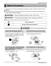
Do not place the power cord near flammable gas or combustibles such as shown below. Gasolin Service Manual 3 Be sure to do. WARNING This symbol indicates the possibility of symbols ...used in this manual are as gasoline, benzene, thinner, etc. • It may cause fire and electric shock. Do not use the power cord near a heater. • Improper assembly or installation may cause incorrect operation, including injury, fire, and electric shock hazards. • It may cause explosion or...
Do not place the power cord near flammable gas or combustibles such as shown below. Gasolin Service Manual 3 Be sure to do. WARNING This symbol indicates the possibility of symbols ...used in this manual are as gasoline, benzene, thinner, etc. • It may cause fire and electric shock. Do not use the power cord near a heater. • Improper assembly or installation may cause incorrect operation, including injury, fire, and electric shock hazards. • It may cause explosion or...
Service Manual
Page 4
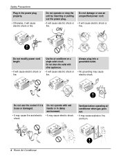
... operate or stop the unit by inserting or pulling out the power plug. • It will cause electric shock or fire. ON Do not modify power cord length. • It will cause electric shock or fire. Do not use an unspecified power cord. • It will cause electric shock or fire. .... Do not operate with other appliances. • It will cause electric shock or fire. Do not share the outlet with wet hands or in the power plug properly. • Otherwise, it is loose or damaged. Safety Precautions Plug in damp environment. • It may cause fire and electric • ...
... operate or stop the unit by inserting or pulling out the power plug. • It will cause electric shock or fire. ON Do not modify power cord length. • It will cause electric shock or fire. Do not use an unspecified power cord. • It will cause electric shock or fire. .... Do not operate with other appliances. • It will cause electric shock or fire. Do not share the outlet with wet hands or in the power plug properly. • Otherwise, it is loose or damaged. Safety Precautions Plug in damp environment. • It may cause fire and electric • ...
Service Manual
Page 5
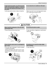
Contact service center after taking the power-plug out from the socket. • It will cause electric shock or failure of the unit when removing the filter. • They are sharp and ... could result in the air conditioner falling out of the window, creating a safety hazard. Safety Precautions If water enters the product, turn off the the power switch of the main body of appliance or performance deteriorate. Do not block the inlet or outlet. • It may enter the unit and degrade...
Contact service center after taking the power-plug out from the socket. • It will cause electric shock or failure of the unit when removing the filter. • They are sharp and ... could result in the air conditioner falling out of the window, creating a safety hazard. Safety Precautions If water enters the product, turn off the the power switch of the main body of appliance or performance deteriorate. Do not block the inlet or outlet. • It may enter the unit and degrade...
Service Manual
Page 6
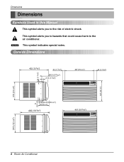
...") 27.5 (1 3/32") 497 (19 9/16") 42 (1 21/32") Cool Energy Saver F1 LOW 'F F2 MED F3 HIGH Fan Dry Timer TEMP MODE TIMER FAN SPEED POWER 347 (13 21/32") 315 (12 3/8") 12 (0.4 1/16") 22.5(0.8 3/32") 243.3(9 9/16") 492 (19 3/8") 497 (19 9/16") Cool Energy Saver F1 LOW 'F F2 MED F3...
...") 27.5 (1 3/32") 497 (19 9/16") 42 (1 21/32") Cool Energy Saver F1 LOW 'F F2 MED F3 HIGH Fan Dry Timer TEMP MODE TIMER FAN SPEED POWER 347 (13 21/32") 315 (12 3/8") 12 (0.4 1/16") 22.5(0.8 3/32") 243.3(9 9/16") 492 (19 3/8") 497 (19 9/16") Cool Energy Saver F1 LOW 'F F2 MED F3...
Service Manual
Page 7
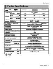
CONTROL AIR DIRECTION CONTROL CONSTRUCTION PROTECTOR COMPRESSOR FAN MOTOR POWER CORD DRAIN SYSTEM NET WEIGHT OUTSIDE DIMENSION (W x H x D) * DB : dry bulb ** WB : wet bulb (lbs/kg) (inch) (mm) LWHD8000R LWHD8000RY5 LWHD8000RY6 LWHD1000R 1ø, 115V, 60Hz 8,000 8,000 10,000 820 820 1,020 7.3...28 71/32 19 9/16 x 12 3/8 x 19 3/8 497 x 315 x 492 Service Manual 7 Product Specifications Specfications ITEMS MODELS POWER SUPPLY CAPACITY (BTU/h) INPUT (W) COOLING RUNNING CURRENT (A) E.E.R (BTU/W.h) OPERATING INDOOR ( C) CONDITION OUTDOOR ( C) REFRIGERANT (R-22) CHARGE...
CONTROL AIR DIRECTION CONTROL CONSTRUCTION PROTECTOR COMPRESSOR FAN MOTOR POWER CORD DRAIN SYSTEM NET WEIGHT OUTSIDE DIMENSION (W x H x D) * DB : dry bulb ** WB : wet bulb (lbs/kg) (inch) (mm) LWHD8000R LWHD8000RY5 LWHD8000RY6 LWHD1000R 1ø, 115V, 60Hz 8,000 8,000 10,000 820 820 1,020 7.3...28 71/32 19 9/16 x 12 3/8 x 19 3/8 497 x 315 x 492 Service Manual 7 Product Specifications Specfications ITEMS MODELS POWER SUPPLY CAPACITY (BTU/h) INPUT (W) COOLING RUNNING CURRENT (A) E.E.R (BTU/W.h) OPERATING INDOOR ( C) CONDITION OUTDOOR ( C) REFRIGERANT (R-22) CHARGE...
Service Manual
Page 8
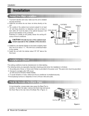
... setting conditions must remain exposed on the unit. Grounding wire (Green or Green and Yellow) is installed securely. 4 Avoid placing furniture or draperies in the power cord. To prevent vibration and noise, make sure the air conditioner is provided in front of the Base Pan. (Figure. 2) 8 Room Air Conditioner Drain Pipe...
... setting conditions must remain exposed on the unit. Grounding wire (Green or Green and Yellow) is installed securely. 4 Avoid placing furniture or draperies in the power cord. To prevent vibration and noise, make sure the air conditioner is provided in front of the Base Pan. (Figure. 2) 8 Room Air Conditioner Drain Pipe...
Service Manual
Page 11
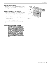
...using a (TYPE A) screw, as shown in Figure. 11. 6. Close the guide panels. Window installation of the guide panels, and save for attaching power cord to the window width. Lift the air conditioner from the window ad remove the sash seal from getting into the room, as shown in... Sash Seal (Type F) Service Manual 11 See ELECTRICAL DATA for reinstallation later. NOTICE REMOVAL FROM WINDOW Trun the air conditioner off, disconnect the power cord, remove the L bracket and the screws installed through the top and bottom of room air conditioner is now completed. Cut the sash seal...
...using a (TYPE A) screw, as shown in Figure. 11. 6. Close the guide panels. Window installation of the guide panels, and save for attaching power cord to the window width. Lift the air conditioner from the window ad remove the sash seal from getting into the room, as shown in... Sash Seal (Type F) Service Manual 11 See ELECTRICAL DATA for reinstallation later. NOTICE REMOVAL FROM WINDOW Trun the air conditioner off, disconnect the power cord, remove the L bracket and the screws installed through the top and bottom of room air conditioner is now completed. Cut the sash seal...
Service Manual
Page 12
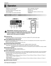
... 2Hours ➔... ) - DISPLAY Cool Energy Saver F1 LOW F2 MED F3 HIGH 'F 6 Fan Dry Timer TEMP 2 MODE TIMER FAN SPEED POWER 3 5 4 1 REMOTE CONTROL Power 1 Temp 2 Fan Speed 4 Timer Mode 5 3 PRECAUTION: The Remote Control unit will start. Energy Saver: If Energy Save mode is set.... lation and service. • Low air-intake, top cooled-air discharge. Operation Operation • Designed for COOLING ONLY. • Powerful and quiet cooling. • Top-down chassis for lower temperature of the room. If the unit is needed. OPERATION MODE SELECTION BUTTON ...
... 2Hours ➔... ) - DISPLAY Cool Energy Saver F1 LOW F2 MED F3 HIGH 'F 6 Fan Dry Timer TEMP 2 MODE TIMER FAN SPEED POWER 3 5 4 1 REMOTE CONTROL Power 1 Temp 2 Fan Speed 4 Timer Mode 5 3 PRECAUTION: The Remote Control unit will start. Energy Saver: If Energy Save mode is set.... lation and service. • Low air-intake, top cooled-air discharge. Operation Operation • Designed for COOLING ONLY. • Powerful and quiet cooling. • Top-down chassis for lower temperature of the room. If the unit is needed. OPERATION MODE SELECTION BUTTON ...
Service Manual
Page 13
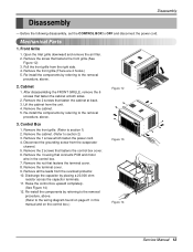
...,000 ohm resistor across the capacitor terminals. 11. Lift the cabinet from the overload protector. 10. Remove the cabinet. (Refer to OFF and disconnect the power cord. Remove the 2 screws that fastens the front grille.(See Figure 12) 3. Re-install the components by referring to the removal procedure, above. 2. ... Raise the control box upward completely. (See Figure 14) 12. Disassembly Disassembly - Remove the cabinet. 5. Figure 12 3. Control Box 1. Remove the 1 screw which fasten the power cord. 4. Remove the nut that fasten the cabinet at back. 3.
...,000 ohm resistor across the capacitor terminals. 11. Lift the cabinet from the overload protector. 10. Remove the cabinet. (Refer to OFF and disconnect the power cord. Remove the 2 screws that fastens the front grille.(See Figure 12) 3. Re-install the components by referring to the removal procedure, above. 2. ... Raise the control box upward completely. (See Figure 14) 12. Disassembly Disassembly - Remove the cabinet. 5. Figure 12 3. Control Box 1. Remove the 1 screw which fasten the power cord. 4. Remove the nut that fasten the cabinet at back. 3.
Service Manual
Page 16
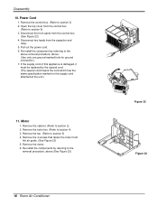
...from the capacitor and relay. 5. If the supply cord of this appliance is damaged, it must be replaced by referring to section 3) 2. Pull out the power cord. 6. Remove the fan. (Refer to the removal procedure, above . (Use only one ground-marked hole for ground connection.) 7. Re-install the ... special cord means the cord which has the same specification marked on the supply cord attached at the unit.) 11. Remove the motor. 6. Power Cord 1. Remove the control box. (Refer to the above removal procedure, above .(See Figure 23) 16 Room Air Conditioner Figure 22 Figure 23
...from the capacitor and relay. 5. If the supply cord of this appliance is damaged, it must be replaced by referring to section 3) 2. Pull out the power cord. 6. Remove the fan. (Refer to the removal procedure, above . (Use only one ground-marked hole for ground connection.) 7. Re-install the ... special cord means the cord which has the same specification marked on the supply cord attached at the unit.) 11. Remove the motor. 6. Power Cord 1. Remove the control box. (Refer to the above removal procedure, above .(See Figure 23) 16 Room Air Conditioner Figure 22 Figure 23
Service Manual
Page 20
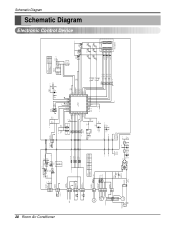
... 20K Option2 Option1 Pipe TH Room TH VAref VSS Osc out Osc in /Reset TEST HVB SW2 SW1 S/V4WAY FAN MOTOR CAPACITOR FAN C HERM MAIN POWER COMP CN-HVB SMW200-03(BL) 33 22 11 12V 11 2 2 CN-CONT J5 SMW200-03(YL) 33 33 2 2 CN-12V SMW200-03(WH) 11... 0.01 10V 50V 11 12V 12 CN-AC/DC 5V 51581-12(YEONHO) 52044-1245(MOLEX) ANGLE RY-COMP G4A-1A-E-LG ZNR01J SVC271D-14A SVC271D-14A FUSE 250VT3.15A POWER TRANS 1 7 D02D D05D 2 D03D 4 D04D + C01D D02D~D05D 1000 1N4004 35V 12V IC01D O I 7812 + C02D C03D 0.1 1000 50V 16V IC02D O I 7805...
... 20K Option2 Option1 Pipe TH Room TH VAref VSS Osc out Osc in /Reset TEST HVB SW2 SW1 S/V4WAY FAN MOTOR CAPACITOR FAN C HERM MAIN POWER COMP CN-HVB SMW200-03(BL) 33 22 11 12V 11 2 2 CN-CONT J5 SMW200-03(YL) 33 33 2 2 CN-12V SMW200-03(WH) 11... 0.01 10V 50V 11 12V 12 CN-AC/DC 5V 51581-12(YEONHO) 52044-1245(MOLEX) ANGLE RY-COMP G4A-1A-E-LG ZNR01J SVC271D-14A SVC271D-14A FUSE 250VT3.15A POWER TRANS 1 7 D02D D05D 2 D03D 4 D04D + C01D D02D~D05D 1000 1N4004 35V 12V IC01D O I 7812 + C02D C03D 0.1 1000 50V 16V IC02D O I 7805...

Service Manual
Page 21
.../DC CN-AC/DC GN/YL BL 5 (GN) MOTOR RD YL DC PCB OR ASSEMBLY RY-LOW RY-MED RY-HI CAPACITOR CN-TH1 YL 2 F POWER 7 C OR(BR) TRANS BK CN-PWR H RD THERMISTOR DC12V SWITCH 6 ZNR01J WH(BL) (Ribbed) FUSE 250V/T3.15A CN-12V BK(BR) (Plain) GN/YL...
.../DC CN-AC/DC GN/YL BL 5 (GN) MOTOR RD YL DC PCB OR ASSEMBLY RY-LOW RY-MED RY-HI CAPACITOR CN-TH1 YL 2 F POWER 7 C OR(BR) TRANS BK CN-PWR H RD THERMISTOR DC12V SWITCH 6 ZNR01J WH(BL) (Ribbed) FUSE 250V/T3.15A CN-12V BK(BR) (Plain) GN/YL...
Service Manual
Page 22
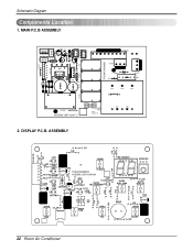
MAIN P.C.B ASSEMBLY CN-CON J1 CN-AC/DC CN-12V D02D D03D D04D D05D IC01D J5 CN-HVB C03T J4 Q02T R01T Q01T J6 D01T C02T J7 CN-TELE CN-TH2 Q03T Q04T J3 RY-HI QIC02DT J2 HEAT SINK RY-MED RY-LOW C02D C04D C05D C01D PCB:6870A90068D CN-MOTOR CN-PWR ZNR01J R01J CN-4WAY C01J E03J E02J E01J J8 RY-4WAY RY-COMP ASSEMBLY:6871A20417C POWER TRANS FUSE 250V/T3.15A E04J E05J 2. ASSEMBLY PCB:6870A90067C ASSEMBLY:6871A20418A 22 Room Air Conditioner DISPLAY P.C.B. Schematic Diagram Components Location 1.
MAIN P.C.B ASSEMBLY CN-CON J1 CN-AC/DC CN-12V D02D D03D D04D D05D IC01D J5 CN-HVB C03T J4 Q02T R01T Q01T J6 D01T C02T J7 CN-TELE CN-TH2 Q03T Q04T J3 RY-HI QIC02DT J2 HEAT SINK RY-MED RY-LOW C02D C04D C05D C01D PCB:6870A90068D CN-MOTOR CN-PWR ZNR01J R01J CN-4WAY C01J E03J E02J E01J J8 RY-4WAY RY-COMP ASSEMBLY:6871A20417C POWER TRANS FUSE 250V/T3.15A E04J E05J 2. ASSEMBLY PCB:6870A90067C ASSEMBLY:6871A20418A 22 Room Air Conditioner DISPLAY P.C.B. Schematic Diagram Components Location 1.
Service Manual
Page 25
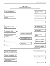
... only fails to start. Gas leakage of feeler bulb of thermostat Check of rotor, metal). Improper wiring. Fails to Start Troubleshooting Guide Check of power voltage. Drop of power source. Defect of fan motor. Loose terminal connection. Check circuit breaker and fuse. Replacement of compressor capacitor. Irregular motor insulation ( ). Irregular motor resistance...
... only fails to start. Gas leakage of feeler bulb of thermostat Check of rotor, metal). Improper wiring. Fails to Start Troubleshooting Guide Check of power voltage. Drop of power source. Defect of fan motor. Loose terminal connection. Check circuit breaker and fuse. Replacement of compressor capacitor. Irregular motor insulation ( ). Irregular motor resistance...
Service Manual
Page 26
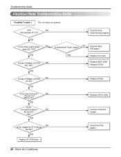
...NO • Check the Main PCB pattern. NO Is the voltage No.18 of IC02D NO DC 5V? YES Is the Trans output power NO about AC 14V? YES ••CChheecckktthheeFFuussee.. ••CChheecckkththeewwiriirninggddiaiaggraramm. . Troubleshooting Guide Electrical Parts Troubleshooting Guide Possible Trouble 1 The unit...~D05D. • Replace IC01D. • Replace IC02D. NO (The No.14 of IC01D NO DC 12V? Is the NO Trans input power AC 115V? Is shorted the Trans. Is the reset circuit good? YES Replace AC PCB Ass'y. • Check the PCB pattern. 26 Room...
...NO • Check the Main PCB pattern. NO Is the voltage No.18 of IC02D NO DC 5V? YES Is the Trans output power NO about AC 14V? YES ••CChheecckktthheeFFuussee.. ••CChheecckkththeewwiriirninggddiaiaggraramm. . Troubleshooting Guide Electrical Parts Troubleshooting Guide Possible Trouble 1 The unit...~D05D. • Replace IC01D. • Replace IC02D. NO (The No.14 of IC01D NO DC 12V? Is the NO Trans input power AC 115V? Is shorted the Trans. Is the reset circuit good? YES Replace AC PCB Ass'y. • Check the PCB pattern. 26 Room...
Service Manual
Page 30
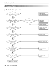
... Air Conditioner NO Is the voltage No.40 of IC01D NO DC 12V? YES ••CChheecckktthheeFFuussee.. ••CChheecckkththeewwiriirninggddiaiaggraramm. . YES Is the Trans output power NO about AC 14V? output? Is the reset circuit OK? Is the NO Trans input...
... Air Conditioner NO Is the voltage No.40 of IC01D NO DC 12V? YES ••CChheecckktthheeFFuussee.. ••CChheecckkththeewwiriirninggddiaiaggraramm. . YES Is the Trans output power NO about AC 14V? output? Is the reset circuit OK? Is the NO Trans input...
Service Manual
Page 34
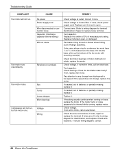
...to 5/16 inch clearance to low speed. Fan Turbo Loose clamper Worn bearings Voltage Wiring REMEDY Check voltage at outlet. If none, check power supply cord. If it hits the base, shim up the bottom of balance, or partially missing, replace it . Check voltage. Check voltage.... CAUSE No power Power supply cord Wire disconnected or connection loose Capacitor (Discharge capacitor before testing.) Will not rotate Revolves on overload. Repair or replace loose terminal....
...to 5/16 inch clearance to low speed. Fan Turbo Loose clamper Worn bearings Voltage Wiring REMEDY Check voltage at outlet. If none, check power supply cord. If it hits the base, shim up the bottom of balance, or partially missing, replace it . Check voltage. Check voltage.... CAUSE No power Power supply cord Wire disconnected or connection loose Capacitor (Discharge capacitor before testing.) Will not rotate Revolves on overload. Repair or replace loose terminal....
Service Manual
Page 37
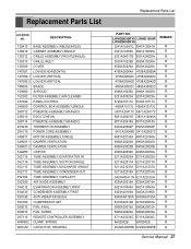
Replacement Parts List LOCATION NO. LWHD8000RY5 LWHD1000R LWHD8000RY6 3041A10041Q 3041A10041H 3091A10056C 3091A10056A 3531A24017B 3531A24020A 3530A10239B 3530A10236A 3550A30226A 3550A30226A 4758A20064A 4758A20069A 4758A20040C 4758A20040C 4758A20040D 4758A20040D 4800A30002C ... BOX ASSEMBLY,SINGLE 268712 PWB(PCB) ASSEMBLY,MAIN(AC) 238310 ESCUTCHEON 268714 PWB(PCB) ASSEMBLY,MAIN(DC) 263230 THERMISTOR ASSEMBLY 264110 POWER CORD ASSEMBLY 346811 MOTOR ASSEMBLY,SINGLE 349001-1 DAMPER,VENTILATION 349001-2 DAMPER,VENTILATION 349480 ORIFICE 352115 TUBE ASSEMBLY,EVAPORATOR IN 35211A TUBE ASSEMBLY,...
Replacement Parts List LOCATION NO. LWHD8000RY5 LWHD1000R LWHD8000RY6 3041A10041Q 3041A10041H 3091A10056C 3091A10056A 3531A24017B 3531A24020A 3530A10239B 3530A10236A 3550A30226A 3550A30226A 4758A20064A 4758A20069A 4758A20040C 4758A20040C 4758A20040D 4758A20040D 4800A30002C ... BOX ASSEMBLY,SINGLE 268712 PWB(PCB) ASSEMBLY,MAIN(AC) 238310 ESCUTCHEON 268714 PWB(PCB) ASSEMBLY,MAIN(DC) 263230 THERMISTOR ASSEMBLY 264110 POWER CORD ASSEMBLY 346811 MOTOR ASSEMBLY,SINGLE 349001-1 DAMPER,VENTILATION 349001-2 DAMPER,VENTILATION 349480 ORIFICE 352115 TUBE ASSEMBLY,EVAPORATOR IN 35211A TUBE ASSEMBLY,...
Service Manual
Page 38
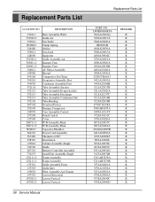
... Tube Assembly,Condenser(Out) Tube,Bending Overload Protect Damper,Compressor Case Assembly,Control Panel,Control Cover PCB Assembly,Main PCB Assembly,Main Capacitor,Film,Box Power Cord Assembly Thermistor,NTC Escutcheon Cabinet Assembly,Single Guide Remote Controller Assembly Install Part Assembly,Single Frame Assembly Frame Assembly Grille Assembly,Front Grille,Inlet...
... Tube Assembly,Condenser(Out) Tube,Bending Overload Protect Damper,Compressor Case Assembly,Control Panel,Control Cover PCB Assembly,Main PCB Assembly,Main Capacitor,Film,Box Power Cord Assembly Thermistor,NTC Escutcheon Cabinet Assembly,Single Guide Remote Controller Assembly Install Part Assembly,Single Frame Assembly Frame Assembly Grille Assembly,Front Grille,Inlet...
Owners Manual
Page 2
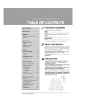
..., Dealer's Name on a _abel on the side of the Date Purchased [] Stap# your receipt to common problems in accordance with the air conditioner. ,ff the power cord requires replacement have an Authorized Servicer install an exact rep|acement part. , |nstallation work must he performed in the chin1 d troubleshooting tips, I_ you...
..., Dealer's Name on a _abel on the side of the Date Purchased [] Stap# your receipt to common problems in accordance with the air conditioner. ,ff the power cord requires replacement have an Authorized Servicer install an exact rep|acement part. , |nstallation work must he performed in the chin1 d troubleshooting tips, I_ you...

