Service Manual
Page 1
website http://www.lgservice.com LG LG Room Air Conditioner SERVICE MANUAL MODEL: LWHD8000R,LWHD8000RY5,LWHD1000R,LWHD8000RY6 CAUTION • BEFORE SERVICING THE UNIT, READ THE SAFETY PRECAUTIONS IN THIS MANUAL. • ONLY FOR AUTHORIZED SERVICE PERSONNEL.
website http://www.lgservice.com LG LG Room Air Conditioner SERVICE MANUAL MODEL: LWHD8000R,LWHD8000RY5,LWHD1000R,LWHD8000RY6 CAUTION • BEFORE SERVICING THE UNIT, READ THE SAFETY PRECAUTIONS IN THIS MANUAL. • ONLY FOR AUTHORIZED SERVICE PERSONNEL.

Service Manual
Page 2
Air Conditioner Service Manual TABLE OF CONTENTS Safety Precautions...3 Dimensions ...6 Outside Dimensions ...6 Product Specifications ...7 Installation ...8 Select the Best Location ...8 Installation Check ...8 How to Secure the Drain Pipe ...8 How to Install...9 Operation ...12 Function of Controls ...12 Disassembly ...13 Mechanical Parts...13 Air handling Parts...14 Electrical Parts ...15 Refrigerating Cycle...17 Schematic Diagram...20...
Air Conditioner Service Manual TABLE OF CONTENTS Safety Precautions...3 Dimensions ...6 Outside Dimensions ...6 Product Specifications ...7 Installation ...8 Select the Best Location ...8 Installation Check ...8 How to Secure the Drain Pipe ...8 How to Install...9 Operation ...12 Function of Controls ...12 Disassembly ...13 Mechanical Parts...13 Air handling Parts...14 Electrical Parts ...15 Refrigerating Cycle...17 Schematic Diagram...20...
Service Manual
Page 4
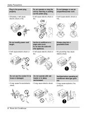
Use the air conditioner on a single outlet circuit. ON Do not modify power cord length. • It will cause electric shock or fire. Do not use...operate or stop the unit by inserting or pulling out the power plug. • It will cause electric shock or fire. Ventilate before operating air conditioner when gas goes out. • It may cause electric shock. ON Do not damage or use the socket if it will cause electric ... • Otherwise, it is loose or damaged. Always plug into a grounded outlet. • No grounding may cause explosion, fire, and burn. 4 Room Air Conditioner
Use the air conditioner on a single outlet circuit. ON Do not modify power cord length. • It will cause electric shock or fire. Do not use...operate or stop the unit by inserting or pulling out the power plug. • It will cause electric shock or fire. Ventilate before operating air conditioner when gas goes out. • It may cause electric shock. ON Do not damage or use the socket if it will cause electric ... • Otherwise, it is loose or damaged. Always plug into a grounded outlet. • No grounding may cause explosion, fire, and burn. 4 Room Air Conditioner
Service Manual
Page 5
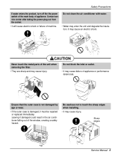
... service center after taking the power-plug out from the socket. • It will cause electric shock or failure of appliance. Do not clean the air conditioner with water. • Water may cause injury. Safety Precautions If water enters the product, turn off the the power switch of the main body of.... Ensure that the outer case is not damaged by age or wear. • If the outer case is damaged, it damaged could result in the air conditioner falling out of appliance or performance deteriorate. Sharp edges Service Manual 5
... service center after taking the power-plug out from the socket. • It will cause electric shock or failure of appliance. Do not clean the air conditioner with water. • Water may cause injury. Safety Precautions If water enters the product, turn off the the power switch of the main body of.... Ensure that the outer case is not damaged by age or wear. • If the outer case is damaged, it damaged could result in the air conditioner falling out of appliance or performance deteriorate. Sharp edges Service Manual 5
Service Manual
Page 6
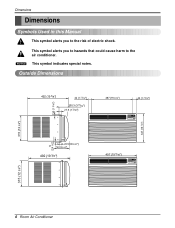
This symbol alerts you to the air conditioner. NOTICE This symbol indicates special notes. Dimensions Dimensions Symbols Used in this Manual This symbol alerts you to hazards that could cause harm to the ... (19 3/8") 497 (19 9/16") Cool Energy Saver F1 LOW 'F F2 MED F3 HIGH Fan Dry Timer TEMP MODE TIMER FAN SPEED POWER 315 (12 3/8") 6 Room Air Conditioner
This symbol alerts you to the air conditioner. NOTICE This symbol indicates special notes. Dimensions Dimensions Symbols Used in this Manual This symbol alerts you to hazards that could cause harm to the ... (19 3/8") 497 (19 9/16") Cool Energy Saver F1 LOW 'F F2 MED F3 HIGH Fan Dry Timer TEMP MODE TIMER FAN SPEED POWER 315 (12 3/8") 6 Room Air Conditioner
Service Manual
Page 8
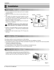
...the cooling effi- Install the unit slanted slightly so the back is provided in front of the Base Pan. (Figure. 2) 8 Room Air Conditioner Drain Pipe Drain Cap Figure 2 Install the unit with the bottom about 1/4"). INSIDE 3. To avoid vibration or noise, make sure the ... will force condensed water to overflow. Connect to the rear hole of the air inlet and outlet. Installation Installation Select the Best Location 1. To prevent vibration and noise, make sure the air conditioner is finished. 1. How to Secure the Drain Pipe In humid weather, excess...
...the cooling effi- Install the unit slanted slightly so the back is provided in front of the Base Pan. (Figure. 2) 8 Room Air Conditioner Drain Pipe Drain Cap Figure 2 Install the unit with the bottom about 1/4"). INSIDE 3. To avoid vibration or noise, make sure the ... will force condensed water to overflow. Connect to the rear hole of the air inlet and outlet. Installation Installation Select the Best Location 1. To prevent vibration and noise, make sure the air conditioner is finished. 1. How to Secure the Drain Pipe In humid weather, excess...
Service Manual
Page 10
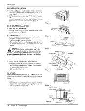
...Remove the backing from window. LOCATING UNIT IN WINDOW Open the window and mark center line on the center of the air conditioner drops into the L bracket, the air conditioner will be centered in window opening as shown in place. Type A Figure 5 SEAL STRIP (TYPE D) Type A Figure...the inner window sill, with screws (TYPE A) as shown. Be sure to the unit with the short side of the air conditioner. IMPORTANT : When the air conditioner drops into the notches of the air conditioner, as shown in Figure. 10. 8" SHORT SIDE 8" OUTSIDE Figure 8 L BRACKET C ool E nergy S aver ...
...Remove the backing from window. LOCATING UNIT IN WINDOW Open the window and mark center line on the center of the air conditioner drops into the L bracket, the air conditioner will be centered in window opening as shown in place. Type A Figure 5 SEAL STRIP (TYPE D) Type A Figure...the inner window sill, with screws (TYPE A) as shown. Be sure to the unit with the short side of the air conditioner. IMPORTANT : When the air conditioner drops into the notches of the air conditioner, as shown in Figure. 10. 8" SHORT SIDE 8" OUTSIDE Figure 8 L BRACKET C ool E nergy S aver ...
Service Manual
Page 11
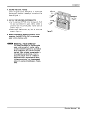
... the power cord, remove the L bracket and the screws installed through the top and bottom of room air conditioner is now completed. keeping a firm grip on the air conditioner, raise the sash, and carefully tilt the air conditioner backward, draining any condensate water. L Bracket Type A Type B Figure 11 Installation Sash Seal (Type ...F) Service Manual 11 Window installation of the guide panels, and save for attaching power cord to the window width. Lift the air conditioner from the window ad remove the sash seal from getting into the room, as shown in Figure. 11. 6. b. 4.
... the power cord, remove the L bracket and the screws installed through the top and bottom of room air conditioner is now completed. keeping a firm grip on the air conditioner, raise the sash, and carefully tilt the air conditioner backward, draining any condensate water. L Bracket Type A Type B Figure 11 Installation Sash Seal (Type ...F) Service Manual 11 Window installation of the guide panels, and save for attaching power cord to the window width. Lift the air conditioner from the window ad remove the sash seal from getting into the room, as shown in Figure. 11. 6. b. 4.
Service Manual
Page 12
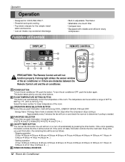
...window of the room. Every time you push this button, it will be set the time when the unit will start. To turn the air conditioner ON, push the button. OPERATION MODE SELECTION BUTTON Every time you push this button controls the time it is off automatically by 1°C)... SPEED SELECTOR Every time you push this button, the remaining time will be turned off ➔ 1Hour ➔ 2Hours ➔ ... ) REMOCON SIGNAL RECEIVER 12 Room Air Conditioner If the unit is set as follows. (Hi [F3] ➔ Low [F1] ➔ Med [F2] ➔ Hi [F3] ➔ Low [F1] ➔...
...window of the room. Every time you push this button, it will be set the time when the unit will start. To turn the air conditioner ON, push the button. OPERATION MODE SELECTION BUTTON Every time you push this button controls the time it is off automatically by 1°C)... SPEED SELECTOR Every time you push this button, the remaining time will be turned off ➔ 1Hour ➔ 2Hours ➔ ... ) REMOCON SIGNAL RECEIVER 12 Room Air Conditioner If the unit is set as follows. (Hi [F3] ➔ Low [F1] ➔ Med [F2] ➔ Hi [F3] ➔ Low [F1] ➔...
Service Manual
Page 14
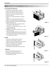
... backward, and pull out from the base pan. 14. Re-install the components by referring to the removal procedure, above . 14 Room Air Conditioner Figure 15 Figure 16 Figure 17 Figure 18 Remove the cabinet. (Refer to the left carefully. 5. Remove the 5 screws which secures the turbo fan. ... (See Figure 18) 3. Re-install the components by referring to the removal procedure, above . 5. Remove the 2 screws that fasten the brace. 5. Shroud 1. Remove the air guide upper.(See Figure 15) 8. Pull out the hook of orifice by referring to section 3) 4. Move the condenser to section...
... backward, and pull out from the base pan. 14. Re-install the components by referring to the removal procedure, above . 14 Room Air Conditioner Figure 15 Figure 16 Figure 17 Figure 18 Remove the cabinet. (Refer to the left carefully. 5. Remove the 5 screws which secures the turbo fan. ... (See Figure 18) 3. Re-install the components by referring to the removal procedure, above . 5. Remove the 2 screws that fasten the brace. 5. Shroud 1. Remove the air guide upper.(See Figure 15) 8. Pull out the hook of orifice by referring to section 3) 4. Move the condenser to section...
Service Manual
Page 16
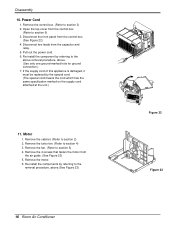
... Figure 22) 4. Remove the motor. 6. Power Cord 1. Pull out the power cord. 6. Remove the turbo fan. (Refer to section 2) 2. Open the top cover from the air guide. (See Figure 23) 5. Motor 1. Remove the cabinet. (Refer to section 4) 3. Remove the 4 screws that fasten the motor from the control box. (Refer to section... only one ground-marked hole for ground connection.) 7. Re-install the components by referring to the above removal procedure, above .(See Figure 23) 16 Room Air Conditioner Figure 22 Figure 23
... Figure 22) 4. Remove the motor. 6. Power Cord 1. Pull out the power cord. 6. Remove the turbo fan. (Refer to section 2) 2. Open the top cover from the air guide. (See Figure 23) 5. Motor 1. Remove the cabinet. (Refer to section 4) 3. Remove the 4 screws that fasten the motor from the control box. (Refer to section... only one ground-marked hole for ground connection.) 7. Re-install the components by referring to the above removal procedure, above .(See Figure 23) 16 Room Air Conditioner Figure 22 Figure 23

Service Manual
Page 18
... A and B for final charging. 6. Discharge the line at the manifold connection. 3) Open valve A and allow pressure to rise to the pinch-off connection. 18 Room Air Conditioner With valve C open slowly with Service valves. 5. Valve B is now ready for a few minutes. Do not add the liquid refrigerant to drop. allow the proper...
... A and B for final charging. 6. Discharge the line at the manifold connection. 3) Open valve A and allow pressure to rise to the pinch-off connection. 18 Room Air Conditioner With valve C open slowly with Service valves. 5. Valve B is now ready for a few minutes. Do not add the liquid refrigerant to drop. allow the proper...
Service Manual
Page 20
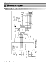
Schematic Diagram Schematic Diagram Electronic Control Device 20 Room Air Conditioner CN-TELE SMW200-03 (RD) 33 22 11 5V C01T 0.1 50V PIPE-TH CN-TH2 SMW250-02 11 22 C02T 0.001 D01T 1N4148 Q04T A104M ... 5V C05D + C06D 220 0.01 10V 50V 11 12V 12 CN-AC/DC 5V 51581-12(YEONHO) 52044-1245(MOLEX) ANGLE RY-COMP G4A-1A-E-LG ZNR01J SVC271D-14A SVC271D-14A FUSE 250VT3.15A POWER TRANS 1 7 D02D D05D 2 D03D 4 D04D + C01D D02D~D05D 1000 1N4004 35V 12V IC01D O I 7812 + C02D C03D...
Schematic Diagram Schematic Diagram Electronic Control Device 20 Room Air Conditioner CN-TELE SMW200-03 (RD) 33 22 11 5V C01T 0.1 50V PIPE-TH CN-TH2 SMW250-02 11 22 C02T 0.001 D01T 1N4148 Q04T A104M ... 5V C05D + C06D 220 0.01 10V 50V 11 12V 12 CN-AC/DC 5V 51581-12(YEONHO) 52044-1245(MOLEX) ANGLE RY-COMP G4A-1A-E-LG ZNR01J SVC271D-14A SVC271D-14A FUSE 250VT3.15A POWER TRANS 1 7 D02D D05D 2 D03D 4 D04D + C01D D02D~D05D 1000 1N4004 35V 12V IC01D O I 7812 + C02D C03D...
Service Manual
Page 22
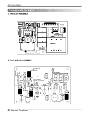
DISPLAY P.C.B. MAIN P.C.B ASSEMBLY CN-CON J1 CN-AC/DC CN-12V D02D D03D D04D D05D IC01D J5 CN-HVB C03T J4 Q02T R01T Q01T J6 D01T C02T J7 CN-TELE CN-TH2 Q03T Q04T J3 RY-HI QIC02DT J2 HEAT SINK RY-MED RY-LOW C02D C04D C05D C01D PCB:6870A90068D CN-MOTOR CN-PWR ZNR01J R01J CN-4WAY C01J E03J E02J E01J J8 RY-4WAY RY-COMP ASSEMBLY:6871A20417C POWER TRANS FUSE 250V/T3.15A E04J E05J 2. Schematic Diagram Components Location 1. ASSEMBLY PCB:6870A90067C ASSEMBLY:6871A20418A 22 Room Air Conditioner
DISPLAY P.C.B. MAIN P.C.B ASSEMBLY CN-CON J1 CN-AC/DC CN-12V D02D D03D D04D D05D IC01D J5 CN-HVB C03T J4 Q02T R01T Q01T J6 D01T C02T J7 CN-TELE CN-TH2 Q03T Q04T J3 RY-HI QIC02DT J2 HEAT SINK RY-MED RY-LOW C02D C04D C05D C01D PCB:6870A90068D CN-MOTOR CN-PWR ZNR01J R01J CN-4WAY C01J E03J E02J E01J J8 RY-4WAY RY-COMP ASSEMBLY:6871A20417C POWER TRANS FUSE 250V/T3.15A E04J E05J 2. Schematic Diagram Components Location 1. ASSEMBLY PCB:6870A90067C ASSEMBLY:6871A20418A 22 Room Air Conditioner
Service Manual
Page 24
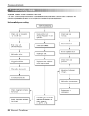
... one is called Starting Failure which is caused from an electrical defect, and the other is ineffective Air Conditioning caused by a defect in refrigeration circuit. 24 Room Air Conditioner Satisfactory operation with temperature difference of inlet & outlet air ; 44~50°F(7~10°C) Replacement of unit if the unit is classified in refrigeration circuit...
... one is called Starting Failure which is caused from an electrical defect, and the other is ineffective Air Conditioning caused by a defect in refrigeration circuit. 24 Room Air Conditioner Satisfactory operation with temperature difference of inlet & outlet air ; 44~50°F(7~10°C) Replacement of unit if the unit is classified in refrigeration circuit...
Service Manual
Page 26
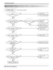
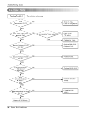
YES ••CChheecckktthheeFFuussee.. ••CChheecckkththeewwiriirninggddiaiaggraramm. . YES Replace AC PCB Ass'y. • Check the PCB pattern. 26 Room Air Conditioner Is the reset circuit good? YES Is output Voltage of IC02D NO DC 5V? Is shorted the Trans. YES Is output Voltage of IC01D NO ...
YES ••CChheecckktthheeFFuussee.. ••CChheecckkththeewwiriirninggddiaiaggraramm. . YES Replace AC PCB Ass'y. • Check the PCB pattern. 26 Room Air Conditioner Is the reset circuit good? YES Is output Voltage of IC02D NO DC 5V? Is shorted the Trans. YES Is output Voltage of IC01D NO ...
Service Manual
Page 28
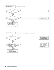
...; Check the pattern of AC PCB Ass'y DC 5V? YES Is the voltage No.3 of NO CN-AC/DC of AC & DC PCB. 28 Room Air Conditioner YES • Check the RY-Hi or RY-Med or RY-Lo. • Check the wiring diagram. • Replace IC01M. • Replace IC01M. Possible Trouble...
...; Check the pattern of AC PCB Ass'y DC 5V? YES Is the voltage No.3 of NO CN-AC/DC of AC & DC PCB. 28 Room Air Conditioner YES • Check the RY-Hi or RY-Med or RY-Lo. • Check the wiring diagram. • Replace IC01M. • Replace IC01M. Possible Trouble...
Service Manual
Page 30
...; Replace IC01D. • Replace IC02D. NO (The No.14 of Micom DC 5V? YES Replace AC PCB Ass'y. • Check the PCB pattern. 30 Room Air Conditioner NO Is the voltage No.40 of Micom is 5V.) YES Is the connection between NO AC and DC OK? YES Is the Trans output...
...; Replace IC01D. • Replace IC02D. NO (The No.14 of Micom DC 5V? YES Replace AC PCB Ass'y. • Check the PCB pattern. 30 Room Air Conditioner NO Is the voltage No.40 of Micom is 5V.) YES Is the connection between NO AC and DC OK? YES Is the Trans output...

Service Manual
Page 32
... Ass'y. • Replace IC01M. • Replace IC01M. • Replace the battery. ••CChheecckk tthheePPCCBBpaptatettrenr.n. • Connect connector to CN-AC/DC exactly. 32 Room Air Conditioner Is the voltage NO.1 or 2 or 4 NO of NO CN-AC/DC OK? Is the voltage of Battery NO over 2.3V?
... Ass'y. • Replace IC01M. • Replace IC01M. • Replace the battery. ••CChheecckk tthheePPCCBBpaptatettrenr.n. • Connect connector to CN-AC/DC exactly. 32 Room Air Conditioner Is the voltage NO.1 or 2 or 4 NO of NO CN-AC/DC OK? Is the voltage of Battery NO over 2.3V?
Service Manual
Page 34
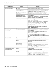
... manufacturer's rating. Replace if shorted, open . Check the wire connections, if loose, repair or replace the terminal. If not per wiring diagram, correct. 34 Room Air Conditioner Troubleshooting Guide COMPLAINT Fan motor will not rotate, replace the motor. Compressor will not run . If knocking sounds continue when running , replace motor.
... manufacturer's rating. Replace if shorted, open . Check the wire connections, if loose, repair or replace the terminal. If not per wiring diagram, correct. 34 Room Air Conditioner Troubleshooting Guide COMPLAINT Fan motor will not rotate, replace the motor. Compressor will not run . If knocking sounds continue when running , replace motor.


