Service Manual
Page 1
website http://www.lgservice.com LG LG Room Air Conditioner SERVICE MANUAL MODEL: LWHD8000R,LWHD8000RY5,LWHD1000R,LWHD8000RY6 CAUTION • BEFORE SERVICING THE UNIT, READ THE SAFETY PRECAUTIONS IN THIS MANUAL. • ONLY FOR AUTHORIZED SERVICE PERSONNEL.
website http://www.lgservice.com LG LG Room Air Conditioner SERVICE MANUAL MODEL: LWHD8000R,LWHD8000RY5,LWHD1000R,LWHD8000RY6 CAUTION • BEFORE SERVICING THE UNIT, READ THE SAFETY PRECAUTIONS IN THIS MANUAL. • ONLY FOR AUTHORIZED SERVICE PERSONNEL.

Service Manual
Page 2
Air Conditioner Service Manual TABLE OF CONTENTS Safety Precautions...3 Dimensions ...6 Outside Dimensions ...6 Product Specifications ...7 Installation ...8 Select the Best Location ...8 Installation Check ...8 How to Secure the Drain Pipe ...8 How to ...
Air Conditioner Service Manual TABLE OF CONTENTS Safety Precautions...3 Dimensions ...6 Outside Dimensions ...6 Product Specifications ...7 Installation ...8 Select the Best Location ...8 Installation Check ...8 How to Secure the Drain Pipe ...8 How to ...
Service Manual
Page 3
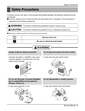
... modify products. • It may cause explosion or fire. Do not place the power cord near flammable gas or combustibles such as shown below. Gasolin Service Manual 3 CAUTION This symbol indicates the possibility of death or serious injury. s Incorrect operation due to do. s Meanings of symbols used in this...
... modify products. • It may cause explosion or fire. Do not place the power cord near flammable gas or combustibles such as shown below. Gasolin Service Manual 3 CAUTION This symbol indicates the possibility of death or serious injury. s Incorrect operation due to do. s Meanings of symbols used in this...
Service Manual
Page 5
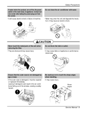
...If the outer case is damaged, it damaged could result in the air conditioner falling out of the window, creating a safety hazard. Sharp edges Service Manual 5 Do not clean the air conditioner with water. • Water may cause injury. Be cautious not to touch the sharp edges when installing....; They are sharp and may cause injury. CAUTION Never touch the metal parts of appliance. It may cause failure of machine. Contact service center after taking the power-plug out from the socket. • It will cause electric shock or failure of appliance or performance deteriorate...
...If the outer case is damaged, it damaged could result in the air conditioner falling out of the window, creating a safety hazard. Sharp edges Service Manual 5 Do not clean the air conditioner with water. • Water may cause injury. Be cautious not to touch the sharp edges when installing....; They are sharp and may cause injury. CAUTION Never touch the metal parts of appliance. It may cause failure of machine. Contact service center after taking the power-plug out from the socket. • It will cause electric shock or failure of appliance or performance deteriorate...
Service Manual
Page 7
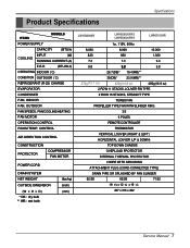
... PROTECTOR COMPRESSOR FAN MOTOR POWER CORD DRAIN SYSTEM NET WEIGHT OUTSIDE DIMENSION (W x H x D) * DB : dry bulb ** WB : wet bulb (lbs/kg) (inch) (mm) LWHD8000R LWHD8000RY5 LWHD8000RY6 LWHD1000R 1ø, 115V, 60Hz 8,000 8,000 10,000 820 820 1,020 7.3 7.3 9.4 9.8 9.8 9.8 26.7(DB)* 19.4(WB)** 370g(13.1 oz) 35(DB)* 23.9(WB)** 420g(14.8 oz) 480g... ATTACHMENT PLUG (CORD-CONNECTED TYPE) DRAIN PIPE OR SPLASHED BY FAN SLINGER 62/28 62/28 71/32 19 9/16 x 12 3/8 x 19 3/8 497 x 315 x 492 Service Manual 7
... PROTECTOR COMPRESSOR FAN MOTOR POWER CORD DRAIN SYSTEM NET WEIGHT OUTSIDE DIMENSION (W x H x D) * DB : dry bulb ** WB : wet bulb (lbs/kg) (inch) (mm) LWHD8000R LWHD8000RY5 LWHD8000RY6 LWHD1000R 1ø, 115V, 60Hz 8,000 8,000 10,000 820 820 1,020 7.3 7.3 9.4 9.8 9.8 9.8 26.7(DB)* 19.4(WB)** 370g(13.1 oz) 35(DB)* 23.9(WB)** 420g(14.8 oz) 480g... ATTACHMENT PLUG (CORD-CONNECTED TYPE) DRAIN PIPE OR SPLASHED BY FAN SLINGER 62/28 62/28 71/32 19 9/16 x 12 3/8 x 19 3/8 497 x 315 x 492 Service Manual 7
Service Manual
Page 9
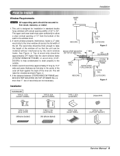
...) DRAIN PIPE 10mm 16mm TYPE D: 1EA (SEAL STRIP) (Adhesive backed) TYPE E: 1EA (SASH SEAL) (Not adhesive backed) TYPE F: 2EA (GUIDE PANEL) TYPE G: 1EA (SUPPORT BACKET) Service Manual 9 See Figure. 4. Install a second wood strip (approximately 6" long by the storm window frame.
...) DRAIN PIPE 10mm 16mm TYPE D: 1EA (SEAL STRIP) (Adhesive backed) TYPE E: 1EA (SASH SEAL) (Not adhesive backed) TYPE F: 2EA (GUIDE PANEL) TYPE G: 1EA (SUPPORT BACKET) Service Manual 9 See Figure. 4. Install a second wood strip (approximately 6" long by the storm window frame.
Service Manual
Page 11
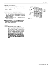
... window ad remove the sash seal from getting into the room, as shown in Figure. 11. L Bracket Type A Type B Figure 11 Installation Sash Seal (Type F) Service Manual 11 INSTALL THE SASH SEAL AND SASH LOCK a. See ELECTRICAL DATA for reinstallation later. keeping a firm grip on the air conditioner, raise the sash, and...
... window ad remove the sash seal from getting into the room, as shown in Figure. 11. L Bracket Type A Type B Figure 11 Installation Sash Seal (Type F) Service Manual 11 INSTALL THE SASH SEAL AND SASH LOCK a. See ELECTRICAL DATA for reinstallation later. keeping a firm grip on the air conditioner, raise the sash, and...
Service Manual
Page 13
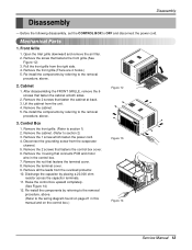
...cover. 6. Discharge the capacitor by referring to the removal procedure, above . 2. Remove the screw that connects PCB and motor wire in this manual and on page 21 in the control box. 7. Disconnect the grounding screw from the unit. 4. Remove all the leads from the right side.... 14) 12. Before the following disassembly, set the CONTROL BOX to the wiring diagram found on the control box.) Figure 13 Figure 14 Service Manual 13 Open the lnlet grille downward and remove the air filter. 2. Pull the front grille from the overload protector. 10. Remove the cabinet...
...cover. 6. Discharge the capacitor by referring to the removal procedure, above . 2. Remove the screw that connects PCB and motor wire in this manual and on page 21 in the control box. 7. Disconnect the grounding screw from the unit. 4. Remove all the leads from the right side.... 14) 12. Before the following disassembly, set the CONTROL BOX to the wiring diagram found on the control box.) Figure 13 Figure 14 Service Manual 13 Open the lnlet grille downward and remove the air filter. 2. Pull the front grille from the overload protector. 10. Remove the cabinet...

Service Manual
Page 15
... the top cover from the overload protec- Re-install the components by referring to the removal procedure, above. 9. Disassembly Figure 19 Figure 20 Figure 21 Service Manual 15 Compressor 1. Remove the overload protector. (Refer to section 2) 2. Remove the overload protector. 6. If there is no valve to section 3) 2. Remove the terminal cover. (See... . Re-install the components by referring to section 2) 2. Remove the cabinet. (Refer to the removal procedure, above . 8. Electrical Parts 7. Leave the valve in place after servicing the system. 3.
... the top cover from the overload protec- Re-install the components by referring to the removal procedure, above. 9. Disassembly Figure 19 Figure 20 Figure 21 Service Manual 15 Compressor 1. Remove the overload protector. (Refer to section 2) 2. Remove the overload protector. 6. If there is no valve to section 3) 2. Remove the terminal cover. (See... . Re-install the components by referring to section 2) 2. Remove the cabinet. (Refer to the removal procedure, above . 8. Electrical Parts 7. Leave the valve in place after servicing the system. 3.
Service Manual
Page 17
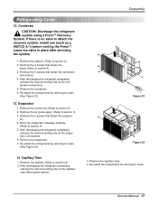
... system. 1. Capillary Tube 1. Refrigerating Cycle 12. After discharging the refrigerant completely, unbraze the interconnecting tube at the evaporator connections. 6. Service Manual 17 Condenser CAUTION: Discharge the refrigerant system using a FreonTM Recovery System. After discharging the refrigerant completely, unbraze the interconnecting tube at the capillary tube.(See ...
... system. 1. Capillary Tube 1. Refrigerating Cycle 12. After discharging the refrigerant completely, unbraze the interconnecting tube at the evaporator connections. 6. Service Manual 17 Condenser CAUTION: Discharge the refrigerant system using a FreonTM Recovery System. After discharging the refrigerant completely, unbraze the interconnecting tube at the capillary tube.(See ...
Service Manual
Page 19
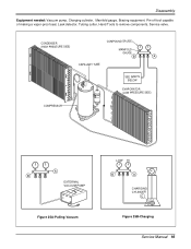
Pin-off tool capable of making a vapor-proof seal, Leak detector, Tubing cutter, Hand Tools to remove components, Service valve. CONDENSER (HIGH PRESSURE SIDE) COMPOUND GAUGE MANIFOLD GAUGE B A CAPILLARY TUBE SEE INSETS BELOW EVAPORATOR (LOW PRESSURE SIDE) COMPRESSOR A B EXTERNAL VACUUM PUMP Figure 25A-Pulling Vacuum LOW HI B A CHARGING CYLINDER C Figure 25B-Charging Service Manual 19 Disassembly Equipment needed: Vacuum pump, Charging cylinder, Manifold gauge, Brazing equipment.
Pin-off tool capable of making a vapor-proof seal, Leak detector, Tubing cutter, Hand Tools to remove components, Service valve. CONDENSER (HIGH PRESSURE SIDE) COMPOUND GAUGE MANIFOLD GAUGE B A CAPILLARY TUBE SEE INSETS BELOW EVAPORATOR (LOW PRESSURE SIDE) COMPRESSOR A B EXTERNAL VACUUM PUMP Figure 25A-Pulling Vacuum LOW HI B A CHARGING CYLINDER C Figure 25B-Charging Service Manual 19 Disassembly Equipment needed: Vacuum pump, Charging cylinder, Manifold gauge, Brazing equipment.

Service Manual
Page 21
DESCRIPTION 1 MOTOR ASSY 2 CAPACITOR 3 COMPRESSOR 4 OVERLOAD PROTECTOR 5 DC PCB ASSEMBLY 6 AC PCB ASSEMBLY 7 THERMISTOR 8 PLASMA FILTER ASSY S: Service Parts N: Non Service Parts Q'TY PER SET 1 1 1 1 1 1 1 1 REMARKS S S S S S S S S Service Manual 21 Wiring Diagram Schematic Diagram 1 BK CN-MOTOR CN-AC/DC CN-AC/DC GN/YL BL 5 (GN) MOTOR RD YL DC PCB OR ASSEMBLY ...
DESCRIPTION 1 MOTOR ASSY 2 CAPACITOR 3 COMPRESSOR 4 OVERLOAD PROTECTOR 5 DC PCB ASSEMBLY 6 AC PCB ASSEMBLY 7 THERMISTOR 8 PLASMA FILTER ASSY S: Service Parts N: Non Service Parts Q'TY PER SET 1 1 1 1 1 1 1 1 REMARKS S S S S S S S S Service Manual 21 Wiring Diagram Schematic Diagram 1 BK CN-MOTOR CN-AC/DC CN-AC/DC GN/YL BL 5 (GN) MOTOR RD YL DC PCB OR ASSEMBLY ...

Service Manual
Page 23
... OUTSIDE COOLING AIR FOR REFRIGERANT PASS THROUGH COMPRESSOR OIL (LIQUID REFRIGERANT) CAPILLARY TUBE Figure 26 LIQUID OUTLET HIGH PRESSURE VAPOR LIQUID REFRIGERANT LOW PRESSURE VAPOR Service Manual 23 Troubleshooting Guide Piping System Troubleshooting Guide CONDENSER COIL FAN MOTOR EVAPORATOR COIL CAPILLARY TUBE COMPRESSOR TURBO FAN Figure 26 is a brief description of the...
... OUTSIDE COOLING AIR FOR REFRIGERANT PASS THROUGH COMPRESSOR OIL (LIQUID REFRIGERANT) CAPILLARY TUBE Figure 26 LIQUID OUTLET HIGH PRESSURE VAPOR LIQUID REFRIGERANT LOW PRESSURE VAPOR Service Manual 23 Troubleshooting Guide Piping System Troubleshooting Guide CONDENSER COIL FAN MOTOR EVAPORATOR COIL CAPILLARY TUBE COMPRESSOR TURBO FAN Figure 26 is a brief description of the...
Service Manual
Page 25
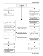
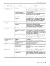
... motor insulation ( ) Replacement of compressor (Motor damaged) Regular but fails to start. Drop of fan motor. Fails to start. Improper wiring. Replacement of power voltage. Service Manual 25 Capacitor check. Check circuit breaker and fuse. Fan only fails to Start Troubleshooting Guide Check of control switch setting. Improper wiring. Check of power...
... motor insulation ( ) Replacement of compressor (Motor damaged) Regular but fails to start. Drop of fan motor. Fails to start. Improper wiring. Replacement of power voltage. Service Manual 25 Capacitor check. Check circuit breaker and fuse. Fan only fails to Start Troubleshooting Guide Check of control switch setting. Improper wiring. Check of power...

Service Manual
Page 27
set lower than Room NO Temp.-0.5°C? YES • Replace IC01M. Service Manual 27 YES • Wait 3 Minutes. • Replace MAIN PCB Ass'y. Troubleshooting Guide Is setting Temp. YES • Select the setting Temp. NO Does the Unit ...
set lower than Room NO Temp.-0.5°C? YES • Replace IC01M. Service Manual 27 YES • Wait 3 Minutes. • Replace MAIN PCB Ass'y. Troubleshooting Guide Is setting Temp. YES • Select the setting Temp. NO Does the Unit ...

Service Manual
Page 29
... NO CN-AC/DC OK? YES Is the connection of Battery NO over 2.3V? Possible Trouble 7 It displays abnormally on DC PCB Ass'y DC 5V? Service Manual 29 YES • Replace the DC PCB Ass'y. • Replace IC01G. • Connect connector to CN-AC/DC exactly. YES • Replace Receiver Ass'y. YES...
... NO CN-AC/DC OK? YES Is the connection of Battery NO over 2.3V? Possible Trouble 7 It displays abnormally on DC PCB Ass'y DC 5V? Service Manual 29 YES • Replace the DC PCB Ass'y. • Replace IC01G. • Connect connector to CN-AC/DC exactly. YES • Replace Receiver Ass'y. YES...
Service Manual
Page 31
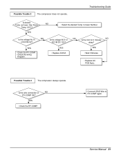
... operate. Possible Trouble 2 The compressor does not operate. YES • Replace IC01M. set lower than Room NO Temp.-0.5°C? YES • Select the desired Temp. Service Manual 31 Is the voltage N0.9 of IC01M DC 12V? NO NO Is the Unit for 3 minutes delay?
... operate. Possible Trouble 2 The compressor does not operate. YES • Replace IC01M. set lower than Room NO Temp.-0.5°C? YES • Select the desired Temp. Service Manual 31 Is the voltage N0.9 of IC01M DC 12V? NO NO Is the Unit for 3 minutes delay?

Service Manual
Page 33
Service Manual 33 YES NO Is the connection of NO CN-AC/DC OK? YES • Replace the DC PCB Ass'y. Troubleshooting Guide • Replace IC01G, IC02G. • Connect connector to CN-AC/DC exactly. • Replace IC03G. Possible Trouble 6 It displays abnormally on AC PCB Ass'y? YES Does the IC03G NO operate normally on DC PCB Ass'y. NO Are IC01G and IC02G OK?
Service Manual 33 YES NO Is the connection of NO CN-AC/DC OK? YES • Replace the DC PCB Ass'y. Troubleshooting Guide • Replace IC01G, IC02G. • Connect connector to CN-AC/DC exactly. • Replace IC03G. Possible Trouble 6 It displays abnormally on AC PCB Ass'y? YES Does the IC03G NO operate normally on DC PCB Ass'y. NO Are IC01G and IC02G OK?
Service Manual
Page 35
...replace the coil. Close if open . (If the compressor temperature is high, remove the overload, cool it, and retest.) Check the voltage. Service Manual 35 Replace the thermistor if the circuit is high, remove the overload, cool, and retest.) If not running, determine the cause. Replace if ...the compressor to overload. Check the compressor for the area to be cooled. Check the system for a restriction. Clean the interior base before servicing.) Compressor Overload Compressor cycles on the coil surface, head pressures will not run, but fan motor runs. If loose or missing, correct. ...
...replace the coil. Close if open . (If the compressor temperature is high, remove the overload, cool it, and retest.) Check the voltage. Service Manual 35 Replace the thermistor if the circuit is high, remove the overload, cool, and retest.) If not running, determine the cause. Replace if ...the compressor to overload. Check the compressor for the area to be cooled. Check the system for a restriction. Clean the interior base before servicing.) Compressor Overload Compressor cycles on the coil surface, head pressures will not run, but fan motor runs. If loose or missing, correct. ...
Service Manual
Page 37
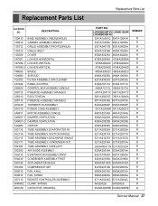
..., TURBO 267110 REMOTE CONTROLLER ASSEMBLY W48602 CLAMP, SPRING W0CZZ CAPACITOR, DRAWING Replacement Parts List PART NO. LWHD8000RY5 LWHD1000R LWHD8000RY6 3041A10041Q 3041A10041H 3091A10056C 3091A10056A 3531A24017B 3531A24020A 3530A10239B 3530A10236A 3550A30226A 3550A30226A 4758A20064A 4758A20069A 4758A20040C 4758A20040C 4758A20040D 4758A20040D 4800A30002C 4800A30002C ...5416A90007A 5900A20015A 5900A20015A 5900A20020A 5900A20020A 6711A20034G 6711A20034C 3H02932B 3H02932B 0CZZA20005B 0CZZA20005B REMARK R R R R R R R R R R R R R R R R R R R R R R R R R R R R R R R R R R R R R Service Manual 37
..., TURBO 267110 REMOTE CONTROLLER ASSEMBLY W48602 CLAMP, SPRING W0CZZ CAPACITOR, DRAWING Replacement Parts List PART NO. LWHD8000RY5 LWHD1000R LWHD8000RY6 3041A10041Q 3041A10041H 3091A10056C 3091A10056A 3531A24017B 3531A24020A 3530A10239B 3530A10236A 3550A30226A 3550A30226A 4758A20064A 4758A20069A 4758A20040C 4758A20040C 4758A20040D 4758A20040D 4800A30002C 4800A30002C ...5416A90007A 5900A20015A 5900A20015A 5900A20020A 5900A20020A 6711A20034G 6711A20034C 3H02932B 3H02932B 0CZZA20005B 0CZZA20005B REMARK R R R R R R R R R R R R R R R R R R R R R R R R R R R R R R R R R R R R R Service Manual 37


