Service Manual
Page 1
website http://www.lgservice.com LG LG Room Air Conditioner SERVICE MANUAL MODEL: LWHD8000R,LWHD8000RY5,LWHD1000R,LWHD8000RY6 CAUTION • BEFORE SERVICING THE UNIT, READ THE SAFETY PRECAUTIONS IN THIS MANUAL. • ONLY FOR AUTHORIZED SERVICE PERSONNEL.
website http://www.lgservice.com LG LG Room Air Conditioner SERVICE MANUAL MODEL: LWHD8000R,LWHD8000RY5,LWHD1000R,LWHD8000RY6 CAUTION • BEFORE SERVICING THE UNIT, READ THE SAFETY PRECAUTIONS IN THIS MANUAL. • ONLY FOR AUTHORIZED SERVICE PERSONNEL.

Service Manual
Page 2
Air Conditioner Service Manual TABLE OF CONTENTS Safety Precautions...3 Dimensions ...6 Outside Dimensions ...6 Product Specifications ...7 Installation ...8 Select the Best Location ...8 Installation Check ...8 How to Secure the Drain Pipe ...8 How to ...
Air Conditioner Service Manual TABLE OF CONTENTS Safety Precautions...3 Dimensions ...6 Outside Dimensions ...6 Product Specifications ...7 Installation ...8 Select the Best Location ...8 Installation Check ...8 How to Secure the Drain Pipe ...8 How to ...
Service Manual
Page 3
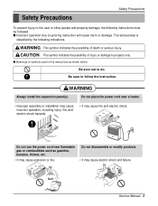
... following indications. s Incorrect operation due to do. WARNING This symbol indicates the possibility of injury or damage to follow the instruction. Gasolin Service Manual 3 The seriousness is classified by the following instructions must be followed. Be sure to property only. WARNING Always install the expansion panel(s). CAUTION ...This symbol indicates the possibility of death or serious injury. s Meanings of symbols used in this manual are as gasoline, benzene, thinner, etc. • It may cause explosion or fire.
... following indications. s Incorrect operation due to do. WARNING This symbol indicates the possibility of injury or damage to follow the instruction. Gasolin Service Manual 3 The seriousness is classified by the following instructions must be followed. Be sure to property only. WARNING Always install the expansion panel(s). CAUTION ...This symbol indicates the possibility of death or serious injury. s Meanings of symbols used in this manual are as gasoline, benzene, thinner, etc. • It may cause explosion or fire.
Service Manual
Page 5
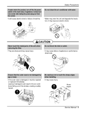
.... • It may enter the unit and degrade the insulation. CAUTION Never touch the metal parts of the window, creating a safety hazard. Sharp edges Service Manual 5 Be cautious not to touch the sharp edges when installing. • It may cause injury. Ensure that the outer case is not damaged by age...
.... • It may enter the unit and degrade the insulation. CAUTION Never touch the metal parts of the window, creating a safety hazard. Sharp edges Service Manual 5 Be cautious not to touch the sharp edges when installing. • It may cause injury. Ensure that the outer case is not damaged by age...
Service Manual
Page 6
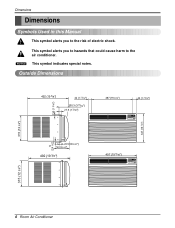
Dimensions Dimensions Symbols Used in this Manual This symbol alerts you to hazards that could cause harm to the risk of electric shock. Outside Dimensions 30 (1 3/16") 492 (19 3/8") 42 (1 21/32") ...
Dimensions Dimensions Symbols Used in this Manual This symbol alerts you to hazards that could cause harm to the risk of electric shock. Outside Dimensions 30 (1 3/16") 492 (19 3/8") 42 (1 21/32") ...
Service Manual
Page 7
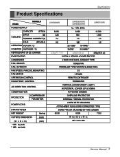
... PROTECTOR COMPRESSOR FAN MOTOR POWER CORD DRAIN SYSTEM NET WEIGHT OUTSIDE DIMENSION (W x H x D) * DB : dry bulb ** WB : wet bulb (lbs/kg) (inch) (mm) LWHD8000R LWHD8000RY5 LWHD8000RY6 LWHD1000R 1ø, 115V, 60Hz 8,000 8,000 10,000 820 820 1,020 7.3 7.3 9.4 9.8 9.8 9.8 26.7(DB)* 19.4(WB)** 370g(13.1 oz) 35(DB)* 23.9(WB)** 420g(14.8 oz) 480g... PLUG (CORD-CONNECTED TYPE) DRAIN PIPE OR SPLASHED BY FAN SLINGER 62/28 62/28 71/32 19 9/16 x 12 3/8 x 19 3/8 497 x 315 x 492 Service Manual 7
... PROTECTOR COMPRESSOR FAN MOTOR POWER CORD DRAIN SYSTEM NET WEIGHT OUTSIDE DIMENSION (W x H x D) * DB : dry bulb ** WB : wet bulb (lbs/kg) (inch) (mm) LWHD8000R LWHD8000RY5 LWHD8000RY6 LWHD1000R 1ø, 115V, 60Hz 8,000 8,000 10,000 820 820 1,020 7.3 7.3 9.4 9.8 9.8 9.8 26.7(DB)* 19.4(WB)** 370g(13.1 oz) 35(DB)* 23.9(WB)** 420g(14.8 oz) 480g... PLUG (CORD-CONNECTED TYPE) DRAIN PIPE OR SPLASHED BY FAN SLINGER 62/28 62/28 71/32 19 9/16 x 12 3/8 x 19 3/8 497 x 315 x 492 Service Manual 7
Service Manual
Page 9
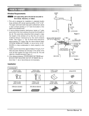
... PIPE 10mm 16mm TYPE D: 1EA (SEAL STRIP) (Adhesive backed) TYPE E: 1EA (SASH SEAL) (Not adhesive backed) TYPE F: 2EA (GUIDE PANEL) TYPE G: 1EA (SUPPORT BACKET) Service Manual 9 Installation How to Install Window Requirements NOTICE All supporting parts should be secured to the inner window sill across the full width of the sill...
... PIPE 10mm 16mm TYPE D: 1EA (SEAL STRIP) (Adhesive backed) TYPE E: 1EA (SASH SEAL) (Not adhesive backed) TYPE F: 2EA (GUIDE PANEL) TYPE G: 1EA (SUPPORT BACKET) Service Manual 9 Installation How to Install Window Requirements NOTICE All supporting parts should be secured to the inner window sill across the full width of the sill...
Service Manual
Page 11
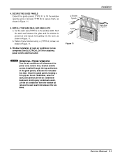
... the screws installed through the top and bottom of room air conditioner is now completed. L Bracket Type A Type B Figure 11 Installation Sash Seal (Type F) Service Manual 11 Close the guide panels. Lift the air conditioner from the window ad remove the sash seal from getting into the room, as shown in...
... the screws installed through the top and bottom of room air conditioner is now completed. L Bracket Type A Type B Figure 11 Installation Sash Seal (Type F) Service Manual 11 Close the guide panels. Lift the air conditioner from the window ad remove the sash seal from getting into the room, as shown in...
Service Manual
Page 13
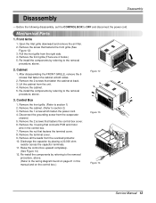
... grille.(There are 4 hooks.) 5. After disassembling the FRONT GRILLE, remove the 6 screws that connects PCB and motor wire in this manual and on the control box.) Figure 13 Figure 14 Service Manual 13 Remove the cabinet. 5. Remove the nut that fastens the control box cover. 6. Raise the control box upward completely. (See...
... grille.(There are 4 hooks.) 5. After disassembling the FRONT GRILLE, remove the 6 screws that connects PCB and motor wire in this manual and on the control box.) Figure 13 Figure 14 Service Manual 13 Remove the cabinet. 5. Remove the nut that fastens the control box cover. 6. Raise the control box upward completely. (See...

Service Manual
Page 15
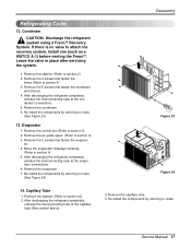
... the 3 nuts and the 3 washers which fasten the compressor. 6. Disconnect all the leads from the overload protec- Disassembly Figure 19 Figure 20 Figure 21 Service Manual 15 Overload Protector 1. Remove the overload protector. 6. Leave the valve in place after servicing the system. 3. Remove all the leads of capacitor terminals. 5. Re-install...
... the 3 nuts and the 3 washers which fasten the compressor. 6. Disconnect all the leads from the overload protec- Disassembly Figure 19 Figure 20 Figure 21 Service Manual 15 Overload Protector 1. Remove the overload protector. 6. Leave the valve in place after servicing the system. 3. Remove all the leads of capacitor terminals. 5. Re-install...
Service Manual
Page 17
... carefully. (Refer to section 4) 3. Re-install the components by referring to notes. (See Figure 24) 14. Re-install the components by referring to notes. Service Manual 17 If there is no valve to section 2) 2. Remove the cabinet. (Refer to attach the recovery system, install one (such as a WATCO A-1) before venting the...
... carefully. (Refer to section 4) 3. Re-install the components by referring to notes. (See Figure 24) 14. Re-install the components by referring to notes. Service Manual 17 If there is no valve to section 2) 2. Remove the cabinet. (Refer to attach the recovery system, install one (such as a WATCO A-1) before venting the...
Service Manual
Page 19
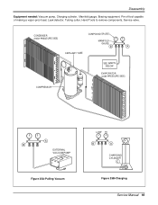
CONDENSER (HIGH PRESSURE SIDE) COMPOUND GAUGE MANIFOLD GAUGE B A CAPILLARY TUBE SEE INSETS BELOW EVAPORATOR (LOW PRESSURE SIDE) COMPRESSOR A B EXTERNAL VACUUM PUMP Figure 25A-Pulling Vacuum LOW HI B A CHARGING CYLINDER C Figure 25B-Charging Service Manual 19 Pin-off tool capable of making a vapor-proof seal, Leak detector, Tubing cutter, Hand Tools to remove components, Service valve. Disassembly Equipment needed: Vacuum pump, Charging cylinder, Manifold gauge, Brazing equipment.
CONDENSER (HIGH PRESSURE SIDE) COMPOUND GAUGE MANIFOLD GAUGE B A CAPILLARY TUBE SEE INSETS BELOW EVAPORATOR (LOW PRESSURE SIDE) COMPRESSOR A B EXTERNAL VACUUM PUMP Figure 25A-Pulling Vacuum LOW HI B A CHARGING CYLINDER C Figure 25B-Charging Service Manual 19 Pin-off tool capable of making a vapor-proof seal, Leak detector, Tubing cutter, Hand Tools to remove components, Service valve. Disassembly Equipment needed: Vacuum pump, Charging cylinder, Manifold gauge, Brazing equipment.

Service Manual
Page 21
... ASSY 2 CAPACITOR 3 COMPRESSOR 4 OVERLOAD PROTECTOR 5 DC PCB ASSEMBLY 6 AC PCB ASSEMBLY 7 THERMISTOR 8 PLASMA FILTER ASSY S: Service Parts N: Non Service Parts Q'TY PER SET 1 1 1 1 1 1 1 1 REMARKS S S S S S S S S Service Manual 21 ASSEMBLY BK RD 3 COMP.
... ASSY 2 CAPACITOR 3 COMPRESSOR 4 OVERLOAD PROTECTOR 5 DC PCB ASSEMBLY 6 AC PCB ASSEMBLY 7 THERMISTOR 8 PLASMA FILTER ASSY S: Service Parts N: Non Service Parts Q'TY PER SET 1 1 1 1 1 1 1 1 REMARKS S S S S S S S S Service Manual 21 ASSEMBLY BK RD 3 COMP.

Service Manual
Page 23
... COOLING AIR FOR REFRIGERANT PASS THROUGH COMPRESSOR OIL (LIQUID REFRIGERANT) CAPILLARY TUBE Figure 26 LIQUID OUTLET HIGH PRESSURE VAPOR LIQUID REFRIGERANT LOW PRESSURE VAPOR Service Manual 23 This will help you to understand the refrigeration cycle and the flow of the important components and their function in the cooling cycle.
... COOLING AIR FOR REFRIGERANT PASS THROUGH COMPRESSOR OIL (LIQUID REFRIGERANT) CAPILLARY TUBE Figure 26 LIQUID OUTLET HIGH PRESSURE VAPOR LIQUID REFRIGERANT LOW PRESSURE VAPOR Service Manual 23 This will help you to understand the refrigeration cycle and the flow of the important components and their function in the cooling cycle.
Service Manual
Page 25
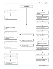
... of feeler bulb of thermostat Check of fan motor capacitor. Defect of control switch. Replacement of compressor (locking of power source. Loose terminal connection. Service Manual 25 Compressor only fails to start . Fan only fails to start .
... of feeler bulb of thermostat Check of fan motor capacitor. Defect of control switch. Replacement of compressor (locking of power source. Loose terminal connection. Service Manual 25 Compressor only fails to start . Fan only fails to start .

Service Manual
Page 27
...-COMP OK? to RY-COMP again. Is the voltage No.10 NO of IC01M 0V? YES • Wait 3 Minutes. • Replace MAIN PCB Ass'y. Service Manual 27 YES • Replace IC01M.
...-COMP OK? to RY-COMP again. Is the voltage No.10 NO of IC01M 0V? YES • Wait 3 Minutes. • Replace MAIN PCB Ass'y. Service Manual 27 YES • Replace IC01M.
Service Manual
Page 28
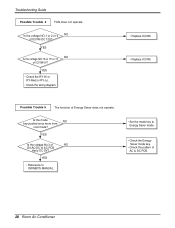
... or 15 or 13 NO of IC01M DC 12V? Is the mode NO key pushed once more from cool mode? YES • Reference to OWNER'S MANUAL. • Set the mode key to Energy Saver mode. • Check the Energy Saver mode key. • Check the pattern of AC & DC PCB. 28...
... or 15 or 13 NO of IC01M DC 12V? Is the mode NO key pushed once more from cool mode? YES • Reference to OWNER'S MANUAL. • Set the mode key to Energy Saver mode. • Check the Energy Saver mode key. • Check the pattern of AC & DC PCB. 28...

Service Manual
Page 29
YES Is the voltage No.10 NO of Battery NO over 2.3V? YES Is the connection of NO CN-AC/DC OK? Service Manual 29 YES NO Is the connection of NO CN-AC/DC OK? Troubleshooting Guide • Replace the battery. ••CChheecckkththeePPCCBBppaattteterrnn.. • Connect connector to ...
YES Is the voltage No.10 NO of Battery NO over 2.3V? YES Is the connection of NO CN-AC/DC OK? Service Manual 29 YES NO Is the connection of NO CN-AC/DC OK? Troubleshooting Guide • Replace the battery. ••CChheecckkththeePPCCBBppaattteterrnn.. • Connect connector to ...
Service Manual
Page 31
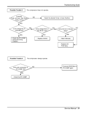
... voltage N0.9 of IC01M 0V? Possible Trouble 3 The compressor always operate. YES • Check the RY-COMP. • Connect LEAD Wire to lower Number. Service Manual 31 Is the voltage No.10 NO of IC01M DC 12V? to RY-COMP again. Is the wire connection of NO RY-COMP OK? YES...
... voltage N0.9 of IC01M 0V? Possible Trouble 3 The compressor always operate. YES • Check the RY-COMP. • Connect LEAD Wire to lower Number. Service Manual 31 Is the voltage No.10 NO of IC01M DC 12V? to RY-COMP again. Is the wire connection of NO RY-COMP OK? YES...

Service Manual
Page 33
YES Does the IC03G NO operate normally on DC PCB Ass'y. YES NO Is the connection of NO CN-AC/DC OK? Troubleshooting Guide • Replace IC01G, IC02G. • Connect connector to CN-AC/DC exactly. • Replace IC03G. YES • Replace the DC PCB Ass'y. Possible Trouble 6 It displays abnormally on AC PCB Ass'y? NO Are IC01G and IC02G OK? Service Manual 33
YES Does the IC03G NO operate normally on DC PCB Ass'y. YES NO Is the connection of NO CN-AC/DC OK? Troubleshooting Guide • Replace IC01G, IC02G. • Connect connector to CN-AC/DC exactly. • Replace IC03G. YES • Replace the DC PCB Ass'y. Possible Trouble 6 It displays abnormally on AC PCB Ass'y? NO Are IC01G and IC02G OK? Service Manual 33


