

Service Manual
Page 2
...39 Operation ...40 Function of control...40 Function of Indoor Unit ...45 Function of Outdoor Unit ...47 Remote Control Operation ...48 Disassembly ...49 Indoor Unit...49 Schematic Diagram...54 Electronic Control Device ...54 Wiring Diagram...58 Components Locations...59 Troubleshooting Guide ...64 Refrigeration Cycle Diagram ...64 Self-diagnosis Function ...65 Cycle Troubleshooting Guide...66 Electronic Parts Troubleshooting Guide 67 General Information...72 2-way, 3-way Valve ...78 Exploded View & Replacement Parts List 82 Indoor Unit ...82 Outdoor Unit ...86 2 Multi type Air Conditioner
...39 Operation ...40 Function of control...40 Function of Indoor Unit ...45 Function of Outdoor Unit ...47 Remote Control Operation ...48 Disassembly ...49 Indoor Unit...49 Schematic Diagram...54 Electronic Control Device ...54 Wiring Diagram...58 Components Locations...59 Troubleshooting Guide ...64 Refrigeration Cycle Diagram ...64 Self-diagnosis Function ...65 Cycle Troubleshooting Guide...66 Electronic Parts Troubleshooting Guide 67 General Information...72 2-way, 3-way Valve ...78 Exploded View & Replacement Parts List 82 Indoor Unit ...82 Outdoor Unit ...86 2 Multi type Air Conditioner
Service Manual
Page 3
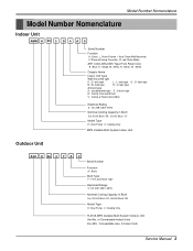
...+ Auto Clean(Wall Mounted) C: Plasma(Ceiling Cassette), G: Low Static Motor ART COOL(DELUXE) Type Front Panel Color B : Blue, D : Wood, M : Metal, R : Mirror, W : White Chassis Name Indoor Unit Type Wall mounted split D : D- look type L : L- look type G : G- look type Artcool type A : standard/wide type D : Deluxe type B : Ceiling Concealed Duct V : Ceiling & Floor(Convertible) Electrical Rating 3: 1Ø, 208~230V, 60Hz Nominal Cooling Capacity in Btu/h Ex) 9,000 Btu/h '09', 12,000 Btu/h '12' Model Type H: Heat Pump C: Cooling Only MPS Variable Multi System Indoor Unit Outdoor...
...+ Auto Clean(Wall Mounted) C: Plasma(Ceiling Cassette), G: Low Static Motor ART COOL(DELUXE) Type Front Panel Color B : Blue, D : Wood, M : Metal, R : Mirror, W : White Chassis Name Indoor Unit Type Wall mounted split D : D- look type L : L- look type G : G- look type Artcool type A : standard/wide type D : Deluxe type B : Ceiling Concealed Duct V : Ceiling & Floor(Convertible) Electrical Rating 3: 1Ø, 208~230V, 60Hz Nominal Cooling Capacity in Btu/h Ex) 9,000 Btu/h '09', 12,000 Btu/h '12' Model Type H: Heat Pump C: Cooling Only MPS Variable Multi System Indoor Unit Outdoor...
Service Manual
Page 8
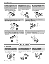
... is not be used for gas (refrigerant) leak- leakage. age. 90° 8 Multi type Air Conditioner s Installation CAUTION Always check for a long time, dis- Ventilate the product from time to ensure that water could step on connect the power supply plug or turn off when cleaning or maintaining the product. • There is drained away properly. Safety Precautions Do not open the inlet grill of product. age. failure...
... is not be used for gas (refrigerant) leak- leakage. age. 90° 8 Multi type Air Conditioner s Installation CAUTION Always check for a long time, dis- Ventilate the product from time to ensure that water could step on connect the power supply plug or turn off when cleaning or maintaining the product. • There is drained away properly. Safety Precautions Do not open the inlet grill of product. age. failure...
Service Manual
Page 9
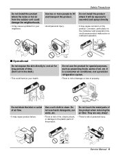
..., solvents, etc. Do not use the product for special purposes, such as preserving foods, works of the product when removing the air filter. Wax Thinner Service Manual 9 Safety Precautions Do not install the product where the noise or hot air from the outdoor unit could damage the neighborhoods. • It may cause a problem for your health. Do not touch the metal parts of art, etc. They are...
..., solvents, etc. Do not use the product for special purposes, such as preserving foods, works of the product when removing the air filter. Wax Thinner Service Manual 9 Safety Precautions Do not install the product where the noise or hot air from the outdoor unit could damage the neighborhoods. • It may cause a problem for your health. Do not touch the metal parts of art, etc. They are...
Service Manual
Page 13
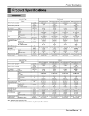
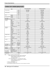
...Fan 1/3.74(95) 36 / 32 / 29 Thermistor 0.197(5.0) 18 2R,15C 1.2 35.2*11.1*6.5(895*282*165) 9.5(20.9) 1/4 (6.35) 3/8 (9.52) 20 38.3*9.1*14.6(973*231*372) 353/719 (792) Indoor Unit Type Nominal Cooling Capacity 5 Model Nominal Heating Capacity 5 Air Circulation H/M/L Setting temperature range(cool/heat) Fan motor Output Model No. Used / Diameter Noise Level (Sound Press,1m) H/M/L Temperature controller Coil Tube Size (OD) Fins per inch No. Product Specifications Product Specifications Indoor Unit Indoor Unit Type Nominal Cooling Capacity 5 Model Nominal Heating...
...Fan 1/3.74(95) 36 / 32 / 29 Thermistor 0.197(5.0) 18 2R,15C 1.2 35.2*11.1*6.5(895*282*165) 9.5(20.9) 1/4 (6.35) 3/8 (9.52) 20 38.3*9.1*14.6(973*231*372) 353/719 (792) Indoor Unit Type Nominal Cooling Capacity 5 Model Nominal Heating Capacity 5 Air Circulation H/M/L Setting temperature range(cool/heat) Fan motor Output Model No. Used / Diameter Noise Level (Sound Press,1m) H/M/L Temperature controller Coil Tube Size (OD) Fins per inch No. Product Specifications Product Specifications Indoor Unit Indoor Unit Type Nominal Cooling Capacity 5 Model Nominal Heating...
Service Manual
Page 14
... Capacitor µF/Vac O.L.P Type(model name) Refrigerant charge Charge g(oz) Type Control Coil Tube Size (OD) inch(mm) Fins per inch No. Multiple piping models Model Cooling Capacity5 Btu/hr W kcal/hr Heating Capacity5 Btu/hr W kcal/hr Input5 Cooling W Heating W Running Current5(208/230V) Cooling A Heating A Power Supply Ø,V,Hz Max. Number of Zero. 2. Fan motor Model Output W Capacitor µF/Vac Fan Type No. Interunit Piping Length Total of innovation some specifications may be changed without notification. 14 Multi type Air Conditioner...
... Capacitor µF/Vac O.L.P Type(model name) Refrigerant charge Charge g(oz) Type Control Coil Tube Size (OD) inch(mm) Fins per inch No. Multiple piping models Model Cooling Capacity5 Btu/hr W kcal/hr Heating Capacity5 Btu/hr W kcal/hr Input5 Cooling W Heating W Running Current5(208/230V) Cooling A Heating A Power Supply Ø,V,Hz Max. Number of Zero. 2. Fan motor Model Output W Capacitor µF/Vac Fan Type No. Interunit Piping Length Total of innovation some specifications may be changed without notification. 14 Multi type Air Conditioner...
Service Manual
Page 20
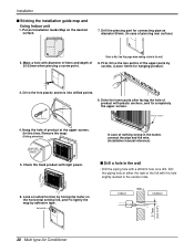
... Fix lightly the map by horizontal meter on this time, Remove the map) (Falling attention) INSTALLATION GUIDE MAP Hanger hole (Rear side of nothing wrong in the matter, connect the pipe and the wire. (Installation manual reference) s Drill a hole in the wall. 8. Look at suited horizon by adhesive tape. Horizontality INSTALLATION GUIDE MAP Indoor WALL Outdoor 5-7mm (0.2~0.3") 20 Multi type Air Conditioner Installation s Sticking the installation guide map and fixing Indoor unit 1. INSTAIIATION GUIDE MAP...
... Fix lightly the map by horizontal meter on this time, Remove the map) (Falling attention) INSTALLATION GUIDE MAP Hanger hole (Rear side of nothing wrong in the matter, connect the pipe and the wire. (Installation manual reference) s Drill a hole in the wall. 8. Look at suited horizon by adhesive tape. Horizontality INSTALLATION GUIDE MAP Indoor WALL Outdoor 5-7mm (0.2~0.3") 20 Multi type Air Conditioner Installation s Sticking the installation guide map and fixing Indoor unit 1. INSTAIIATION GUIDE MAP...
Service Manual
Page 22
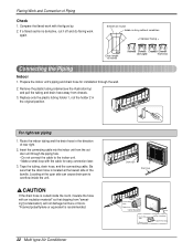
... outdoor unit through the wall. 2. Tape the tubing, drain hose, and the connecting cable. Be sure that dripping from "sweating"(condensation) will not damage furniture or floors. *Foamed polyethylene or equivalent is shiny without scratches = Improper flaring = Even length all round Inside is recommended. 22 Multi type Air Conditioner Drain hose Drain hose Tape Connecting pipe Drain hose Connecting cable Connecting cable Drain hose Loop Gas side piping Liquid side piping Locating...
... outdoor unit through the wall. 2. Tape the tubing, drain hose, and the connecting cable. Be sure that dripping from "sweating"(condensation) will not damage furniture or floors. *Foamed polyethylene or equivalent is shiny without scratches = Improper flaring = Even length all round Inside is recommended. 22 Multi type Air Conditioner Drain hose Drain hose Tape Connecting pipe Drain hose Connecting cable Connecting cable Drain hose Loop Gas side piping Liquid side piping Locating...
Service Manual
Page 24
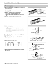
... the indoor unit, install the drain pipe. 24 Multi type Air Conditioner Indoor unit Installation plate 8cm Spacer Indoor unit tubing Flare nut Pipes Wrench Indoor unit tubing Open-end wrench (fixed) Flare nut Connection pipe Drain hose Indoor unit drain hose Adhesive Vinyl tape (narrow) Flaring Work and Connection of the pipes and sufficiently tighten the flare nut by hand. 2. Outside diameter mm inch Ø6.35 1/4 Ø9.52 3/8 Torque kg.m 1.8 4.2 3. Indoor unit installation • Hang the indoor unit from the wall...
... the indoor unit, install the drain pipe. 24 Multi type Air Conditioner Indoor unit Installation plate 8cm Spacer Indoor unit tubing Flare nut Pipes Wrench Indoor unit tubing Open-end wrench (fixed) Flare nut Connection pipe Drain hose Indoor unit drain hose Adhesive Vinyl tape (narrow) Flaring Work and Connection of the pipes and sufficiently tighten the flare nut by hand. 2. Outside diameter mm inch Ø6.35 1/4 Ø9.52 3/8 Torque kg.m 1.8 4.2 3. Indoor unit installation • Hang the indoor unit from the wall...
Service Manual
Page 30
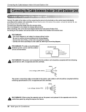
... following specifications (ETL recognized and CSA certified). RECOMMAND: • The circuit diagram is not subject to the electrical diagram behind the front panel of Indoor Unit. RECOMMAND: Provide a circuit breaker between Indoor Unit and Outdoor Unit Connect the cable to the outdoor unit connection. (Ensure that not to the wiring diagram. Connecting the Cable between Indoor Unit and Outdoor Unit Connecting the Cable between power source and the outdoor unit as the fixture. 30 Multi type Air Conditioner...
... following specifications (ETL recognized and CSA certified). RECOMMAND: • The circuit diagram is not subject to the electrical diagram behind the front panel of Indoor Unit. RECOMMAND: Provide a circuit breaker between Indoor Unit and Outdoor Unit Connect the cable to the outdoor unit connection. (Ensure that not to the wiring diagram. Connecting the Cable between Indoor Unit and Outdoor Unit Connecting the Cable between power source and the outdoor unit as the fixture. 30 Multi type Air Conditioner...
Service Manual
Page 35
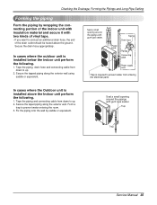
In cases where the outdoor unit is installed below the indoor unit perform the following . 1. Seal a small opening around the pipings with gum type sealer. Taping Drain hose Plastic band Pipings Connecting cable Power supply cord • Trap is installed above the ground. Secure the taped piping along the exterior wall using saddle or equivalent. Secure the tapped piping along the exterior wall. Tape the piping and connecting cable from down...
In cases where the outdoor unit is installed below the indoor unit perform the following . 1. Seal a small opening around the pipings with gum type sealer. Taping Drain hose Plastic band Pipings Connecting cable Power supply cord • Trap is installed above the ground. Secure the taped piping along the exterior wall using saddle or equivalent. Secure the tapped piping along the exterior wall. Tape the piping and connecting cable from down...
Service Manual
Page 39
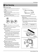
... are fully open. 1) Prepare remote controller Remove the battery cover by pushing it according to the trouble of the unit is carried out firstly, it leads to the arrow direction. Ensure the difference between the intake temperature and the discharge is more than 8°C(46°F) (Cooling) or reversely (Heating). The pressure of air. 3. s When installing on a concrete or rigid mount. Refrigerant Outside ambient TEMP. s For...
... are fully open. 1) Prepare remote controller Remove the battery cover by pushing it according to the trouble of the unit is carried out firstly, it leads to the arrow direction. Ensure the difference between the intake temperature and the discharge is more than 8°C(46°F) (Cooling) or reversely (Heating). The pressure of air. 3. s When installing on a concrete or rigid mount. Refrigerant Outside ambient TEMP. s For...

Service Manual
Page 40
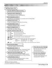
...; Flashing while in disconnection or short in Thermistor (3 sec off / 0.5 sec on) Sleep Timer Indicator • On while in sleep timer mode, off when sleep timer cancel or appliance operation pause Timer Indicator • On while in defrost control s Cooling Mode Operation • When the intake air temperature reaches 0.5°C(32.9°F) below the setting temp, the compressor and the outdoor fan stop. • When it reaches 0.5°C(32.9°F) above the setting temp, they start...
...; Flashing while in disconnection or short in Thermistor (3 sec off / 0.5 sec on) Sleep Timer Indicator • On while in sleep timer mode, off when sleep timer cancel or appliance operation pause Timer Indicator • On while in defrost control s Cooling Mode Operation • When the intake air temperature reaches 0.5°C(32.9°F) below the setting temp, the compressor and the outdoor fan stop. • When it reaches 0.5°C(32.9°F) above the setting temp, they start...
Service Manual
Page 43
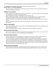
... reset to those of the sleep timer, the setting temperature increases by 1°C(33.8°F). s Jet Cool Mode Operation • While in heating mode or Fuzzy operation, the Jet Cool key cannot be input. • While in cooling mode operation, 30 min later since the start of the initial cooling mode and then operated in order that the air outflow could reach further. randomly by the timer, the pause continues. Service Manual 43 s Sleep Timer Operation...
... reset to those of the sleep timer, the setting temperature increases by 1°C(33.8°F). s Jet Cool Mode Operation • While in heating mode or Fuzzy operation, the Jet Cool key cannot be input. • While in cooling mode operation, 30 min later since the start of the initial cooling mode and then operated in order that the air outflow could reach further. randomly by the timer, the pause continues. Service Manual 43 s Sleep Timer Operation...

Service Manual
Page 44
... switched from the forced operation position to the Auto Restarting position or the remote control position, the forced operation is canceled and the appliance stops operating. • In the forced operation mode, the indoor fan is set according to the intake air temperature as follows. 24°C(75.2°F)≤Intake Air Temp ➲ Cooling Mode Operation, 22°C(71.6°F), High Speed 21°C(69.8°F)≤Intake Air Temp tion condition...
... switched from the forced operation position to the Auto Restarting position or the remote control position, the forced operation is canceled and the appliance stops operating. • In the forced operation mode, the indoor fan is set according to the intake air temperature as follows. 24°C(75.2°F)≤Intake Air Temp ➲ Cooling Mode Operation, 22°C(71.6°F), High Speed 21°C(69.8°F)≤Intake Air Temp tion condition...
Service Manual
Page 45
... minutes. Service Manual 45 Sleep Mode Auto Control • The fan is switched to low speed. * Airflow Direction Control • The louver can be set at 27°C(80.6°F). Hot-start after 1, 2, 3, 4, 5, 6, 7 hours. Sleep Mode : Lights up during the system operation. Natural Air Control by Remote controller Sensing the Room Temperature • Room temperature sensor. (THERMISTOR) Room temperature control • Maintains the room temperature in accordance with the Setting Temp. Indoor Fan Speed Control • High, Med, Low, Chaos, Jet Cool Operation indication Lamps...
... minutes. Service Manual 45 Sleep Mode Auto Control • The fan is switched to low speed. * Airflow Direction Control • The louver can be set at 27°C(80.6°F). Hot-start after 1, 2, 3, 4, 5, 6, 7 hours. Sleep Mode : Lights up during the system operation. Natural Air Control by Remote controller Sensing the Room Temperature • Room temperature sensor. (THERMISTOR) Room temperature control • Maintains the room temperature in accordance with the Setting Temp. Indoor Fan Speed Control • High, Med, Low, Chaos, Jet Cool Operation indication Lamps...

Service Manual
Page 46
... : Lights up during Timer operation. : Lights up during Defrost Mode or Hot Start operation.(Heat pump model only) : Lights up and down automatically. Airflow Direction Control • The louver can be reached at the desired position or swing up during defrosting. Sleep Mode Auto Control • The fan is automatically switched from high to be stopped after 1, 2, 3, 4, 5, 6, 7 hours. Defrost(Deice) control (Heating) • Both the indoor and outdoor fan stops during outdoor unit operation.(Cooling model only) Desire temperature For cooling,dehumidification,heating modes...
... : Lights up during Timer operation. : Lights up during Defrost Mode or Hot Start operation.(Heat pump model only) : Lights up and down automatically. Airflow Direction Control • The louver can be reached at the desired position or swing up during defrosting. Sleep Mode Auto Control • The fan is automatically switched from high to be stopped after 1, 2, 3, 4, 5, 6, 7 hours. Defrost(Deice) control (Heating) • Both the indoor and outdoor fan stops during outdoor unit operation.(Cooling model only) Desire temperature For cooling,dehumidification,heating modes...
Service Manual
Page 48
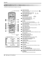
... direction. 48 Multi type Air Conditioner Signal transmitter 5 1 6 3 4 2 10 CANCEL 7 9 ON OFF SET 11 AUTO CLEAN 16 8 12 °C/°F 13 17 18 14 15 Flip-up door (opened) Operation Mode Cooling Operation Auto Operation Healthy Dehumidification Operation Heating Operation • Cooling Model( ), Heat Pump Model( ) 1 START/STOP BUTTON Operation starts when this button is pressed and stops when the button is pressed again. 2 OPERATION MODE SELECTION BUTTON Used to select the operation mode. (Heat Pump) (Cooling Only) 3 ROOM TEMPERATURE SETTING BUTTONS Used...
... direction. 48 Multi type Air Conditioner Signal transmitter 5 1 6 3 4 2 10 CANCEL 7 9 ON OFF SET 11 AUTO CLEAN 16 8 12 °C/°F 13 17 18 14 15 Flip-up door (opened) Operation Mode Cooling Operation Auto Operation Healthy Dehumidification Operation Heating Operation • Cooling Model( ), Heat Pump Model( ) 1 START/STOP BUTTON Operation starts when this button is pressed and stops when the button is pressed again. 2 OPERATION MODE SELECTION BUTTON Used to select the operation mode. (Heat Pump) (Cooling Only) 3 ROOM TEMPERATURE SETTING BUTTONS Used...
Service Manual
Page 65
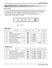
... Outdoor Error Error code Description MPS Variable LED1(Red) LED2(Green) Indoor Status 33 D-Pipe High(Normal) 44 Outdoor Air Thermistor Error(Open/Short) 45 Cond Pipe Thermistor Error(Open/Short) 47 Const. D-Pipe Thermistor Error(Open/Short) 51 Capcity Error(High/Low) 3 times 3 times OFF 4 times 4 times OFF 4 times 5 times OFF 4 times 7 times OFF 5 times 1 times OFF Service Manual 65 Troubleshooting Guide Self-diagnosis Function s Error Indicator • The function is to self-diagnoisis airconditioner...
... Outdoor Error Error code Description MPS Variable LED1(Red) LED2(Green) Indoor Status 33 D-Pipe High(Normal) 44 Outdoor Air Thermistor Error(Open/Short) 45 Cond Pipe Thermistor Error(Open/Short) 47 Const. D-Pipe Thermistor Error(Open/Short) 51 Capcity Error(High/Low) 3 times 3 times OFF 4 times 4 times OFF 4 times 5 times OFF 4 times 7 times OFF 5 times 1 times OFF Service Manual 65 Troubleshooting Guide Self-diagnosis Function s Error Indicator • The function is to self-diagnoisis airconditioner...
Service Manual
Page 67
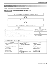
...-DISP1 The operation check of the P.C.B. Ass'y (Fuse, Noise Filter, Power Transformer, IC01D, IC02D, etc.) YES • Primarily, the operating condi- Ass'y Procedure 1) The input voltage of micom pin 29 : DC4.5V↑ Remedy 1) Replace power transfomer. 2) Replace power transfomer. 3) Replace IC01D. 4) Replace IC02D. 5) Replace IC01A. Electronic Parts Troubleshooting Guide ❇ Refer to the unit. • The connecting method of Indoor/Outdoor connecting cable (each color) • The P.W.B. Service Manual 67 former...
...-DISP1 The operation check of the P.C.B. Ass'y (Fuse, Noise Filter, Power Transformer, IC01D, IC02D, etc.) YES • Primarily, the operating condi- Ass'y Procedure 1) The input voltage of micom pin 29 : DC4.5V↑ Remedy 1) Replace power transfomer. 2) Replace power transfomer. 3) Replace IC01D. 4) Replace IC02D. 5) Replace IC01A. Electronic Parts Troubleshooting Guide ❇ Refer to the unit. • The connecting method of Indoor/Outdoor connecting cable (each color) • The P.W.B. Service Manual 67 former...


