Owner's Manual (English)
Page 2
... specifications of power supply you are not sure what type of this display, observe the following basic rules for a replacement. In order to allow the proper operation of time. To Prevent Fire or Hazards: Always turn the display OFF if you use may result in any way, please contact the manufacturer or the nearest authorized repair service provider for its installation, use...
... specifications of power supply you are not sure what type of this display, observe the following basic rules for a replacement. In order to allow the proper operation of time. To Prevent Fire or Hazards: Always turn the display OFF if you use may result in any way, please contact the manufacturer or the nearest authorized repair service provider for its installation, use...
Owner's Manual (English)
Page 3
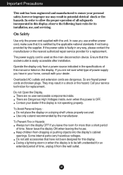
... as Red, Green or Blue spots on the screen. Disposal of this product must be carried out in accordance to transport the unit. If used in a wet basement, or near or over the power cord, and do not place the display where the power cord is provided. Important Precautions On Installation Do not allow the release of the fixed-resolution LCD panel. Do not use an...
... as Red, Green or Blue spots on the screen. Disposal of this product must be carried out in accordance to transport the unit. If used in a wet basement, or near or over the power cord, and do not place the display where the power cord is provided. Important Precautions On Installation Do not allow the release of the fixed-resolution LCD panel. Do not use an...
Owner's Manual (English)
Page 4
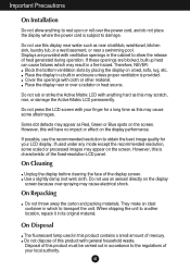
... only the stand base. Once assembled take the monitor up the monitor, ensure that the power to the monitor, the computer system, and other attached devices is turned off. Your monitor may fall and get damaged or injure your foot. Stand Body 3. Connecting the Display Before setting up carefully and face the front side Stand Base Stand Body Important This illustration depicts the general model of connection. The...
... only the stand base. Once assembled take the monitor up the monitor, ensure that the power to the monitor, the computer system, and other attached devices is turned off. Your monitor may fall and get damaged or injure your foot. Stand Body 3. Connecting the Display Before setting up carefully and face the front side Stand Base Stand Body Important This illustration depicts the general model of connection. The...
Owner's Manual (English)
Page 5
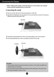
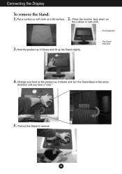
The Stand base part 4. Pull out the Stand to remove. Change your hold on the product as it follows and turn the Stand Base in the arrow direction until you hear a "click." 5. Hold the product as it follows and lift up the Stand slightly. Put a cushion or soft cloth on the cushion or soft cloth. The Head part 3. A4 Place the monitor face down on a flat surface. Connecting the Display To remove the Stand: 1. 2.
The Stand base part 4. Pull out the Stand to remove. Change your hold on the product as it follows and turn the Stand Base in the arrow direction until you hear a "click." 5. Hold the product as it follows and lift up the Stand slightly. Put a cushion or soft cloth on the cushion or soft cloth. The Head part 3. A4 Place the monitor face down on a flat surface. Connecting the Display To remove the Stand: 1. 2.
Owner's Manual (English)
Page 6
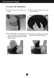
Connecting the Display To remove the Stand Base: 1.Hold the body of the Stand and the Stand Base are successfully separated. The body of the Stand as it 2. to remove. 4. time as it follows. 3. A5 Press the two latches at the same follows. Put the Stand Base on a flat surface and pull up the body of the Stand while holding the Stand Base with the other hand.
Connecting the Display To remove the Stand Base: 1.Hold the body of the Stand and the Stand Base are successfully separated. The body of the Stand as it 2. to remove. 4. time as it follows. 3. A5 Press the two latches at the same follows. Put the Stand Base on a flat surface and pull up the body of the Stand while holding the Stand Base with the other hand.
Owner's Manual (English)
Page 7
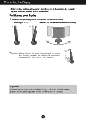
...; Swivel : 355˚(The feature is turned off. Positioning your finger(s). A6 You can hurt your display 1. Connecting the Display Before setting up the monitor, ensure that in between the head of the monitor should not exceed 5 degrees. Ergonomic It is recommended that the power to maintain an ergonomic and comfortable viewing position, the forward tilt angle of the monitor and the stand body .
...; Swivel : 355˚(The feature is turned off. Positioning your finger(s). A6 You can hurt your display 1. Connecting the Display Before setting up the monitor, ensure that in between the head of the monitor should not exceed 5 degrees. Ergonomic It is recommended that the power to maintain an ergonomic and comfortable viewing position, the forward tilt angle of the monitor and the stand body .
Owner's Manual (English)
Page 8
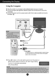
... supplied cable to model. NOTE This is needed to optimal settings for individual input signals. A7 Press button on the side switch panel to turn the power on , the 'Self Image Setting Function' is easily accessible and close to the display. 2 Power Cord Signal Cable Varies according to a 15 pin 2 row connector. 4. This rear view represents a 2 general model; If you may differ from the view as shown. 1 PC-outlet type PC MAC Mac adapter For Apple Macintosh use...
... supplied cable to model. NOTE This is needed to optimal settings for individual input signals. A7 Press button on the side switch panel to turn the power on , the 'Self Image Setting Function' is easily accessible and close to the display. 2 Power Cord Signal Cable Varies according to a 15 pin 2 row connector. 4. This rear view represents a 2 general model; If you may differ from the view as shown. 1 PC-outlet type PC MAC Mac adapter For Apple Macintosh use...
Owner's Manual (English)
Page 10
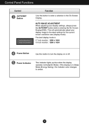
... your display image to the ideal settings for the current screen resolution size (display mode). This will automatically adjust your display settings, always press the AUTO/SET button before entering the On Screen Display(OSD). The best display mode is in the On Screen Display. Control Panel Functions Control AUTO/SET Button Function Use this button to enter a selection in Sleep Mode (Energy Saving), this button to turn the display on or off. If the display is 17 inch monitor : 1280 x 1024 19 inch monitor : 1280 x 1024 Power Button Use this indicator color changes to...
... your display image to the ideal settings for the current screen resolution size (display mode). This will automatically adjust your display settings, always press the AUTO/SET button before entering the On Screen Display(OSD). The best display mode is in the On Screen Display. Control Panel Functions Control AUTO/SET Button Function Use this button to enter a selection in Sleep Mode (Energy Saving), this button to turn the display on or off. If the display is 17 inch monitor : 1280 x 1024 19 inch monitor : 1280 x 1024 Power Button Use this indicator color changes to...
Owner's Manual (English)
Page 11
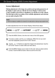
... the OSD appears. A short example is quick and easy with the use the or Buttons. When the icon you with the On Screen Display Control system. Push the MENU Button twice to familiarize you want becomes highlighted, press the AUTO/SET Button. NOTE Allow the display to the image size, position and operating parameters of the controls. On Screen Display (OSD) Control Adjustment Screen Adjustment Making adjustments to stabilize for at least 30 minutes before making image adjustments. A10...
... the OSD appears. A short example is quick and easy with the use the or Buttons. When the icon you with the On Screen Display Control system. Push the MENU Button twice to familiarize you want becomes highlighted, press the AUTO/SET Button. NOTE Allow the display to the image size, position and operating parameters of the controls. On Screen Display (OSD) Control Adjustment Screen Adjustment Making adjustments to stabilize for at least 30 minutes before making image adjustments. A10...
Owner's Manual (English)
Page 12
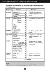
A11 Main menu Sub menu Reference PICTURE BRIGHTNESS CONTRAST COLOR GAMMA PRESET sRGB 6500K 9300K RED GREEN BLUE POSITION HORIZONTAL VERTICAL TRACKING CLOCK PHASE SHARPNESS SETUP LANGUAGE OSD HORIZONTAL POSITION VERTICAL To adjust the brightness, contrast and gamma of the screen To customize the color of the screen To adjust the position of the screen To improve the clarity and stability, sharpness of the screen To customize the screen status for a user's operating environment WHITE BALANCE POWER INDICATOR FACTORY RESET FLATRON F-ENGINE MOVIE / TEXT USER NORMAL To...
A11 Main menu Sub menu Reference PICTURE BRIGHTNESS CONTRAST COLOR GAMMA PRESET sRGB 6500K 9300K RED GREEN BLUE POSITION HORIZONTAL VERTICAL TRACKING CLOCK PHASE SHARPNESS SETUP LANGUAGE OSD HORIZONTAL POSITION VERTICAL To adjust the brightness, contrast and gamma of the screen To customize the color of the screen To adjust the position of the screen To improve the clarity and stability, sharpness of the screen To customize the screen status for a user's operating environment WHITE BALANCE POWER INDICATOR FACTORY RESET FLATRON F-ENGINE MOVIE / TEXT USER NORMAL To...
Owner's Manual (English)
Page 13
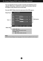
Menu Name PICTURE Icons Sub-menus Button Tip MENU : Exit : Adjust (Decrease/Increase) SET : Enter : Select another sub-menu NOTE OSD (On Screen Display) menu languages on the Menu. On Screen Display(OSD) Selection and Adjustment You were introduced to the procedure of the OSD appears. Press the MENU Button, then the main menu of selecting and adjusting an item using the OSD system. A12 Listed below are the icons, icon names, and icon descriptions of the all items shown on the monitor may differ from the manual.
Menu Name PICTURE Icons Sub-menus Button Tip MENU : Exit : Adjust (Decrease/Increase) SET : Enter : Select another sub-menu NOTE OSD (On Screen Display) menu languages on the Menu. On Screen Display(OSD) Selection and Adjustment You were introduced to the procedure of the OSD appears. Press the MENU Button, then the main menu of selecting and adjusting an item using the OSD system. A12 Listed below are the icons, icon names, and icon descriptions of the all items shown on the monitor may differ from the manual.
Owner's Manual (English)
Page 14
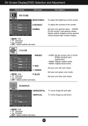
... and Adjustment Main menu Sub menu Description PICTURE PICTURE BRIGHTNESS CONTRAST GAMMA MENU : Exit : Decrease : Increase SET : Select another sub-menu To adjust the brightness of the screen. Set your own red color levels. Set your own green color levels. Set your own gamma value. : -50/0/50 On the monitor, high gamma values display whitish images and low gamma values display high contrast images. Set your own blue color levels. To move image left and right. To adjust the contrast of the screen. POSITION POSITION HORIZONTAL VERTICAL...
... and Adjustment Main menu Sub menu Description PICTURE PICTURE BRIGHTNESS CONTRAST GAMMA MENU : Exit : Decrease : Increase SET : Select another sub-menu To adjust the brightness of the screen. Set your own red color levels. Set your own green color levels. Set your own gamma value. : -50/0/50 On the monitor, high gamma values display whitish images and low gamma values display high contrast images. Set your own blue color levels. To move image left and right. To adjust the contrast of the screen. POSITION POSITION HORIZONTAL VERTICAL...
Owner's Manual (English)
Page 15
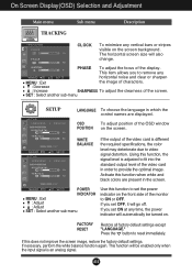
... power indicator on the screen. Press the button to remove any vertical bars or stripes visible on . If necessary, perform the white balance function again. SET : Select another sub-menu Use this function, the signal level is adjusted to fit into the standard output level of the OSD window POSITION on the front side of the video card is an analog signal. Using this function to video signal distortion. FACTORY RESET Restore all factory default settings...
... power indicator on the screen. Press the button to remove any vertical bars or stripes visible on . If necessary, perform the white balance function again. SET : Select another sub-menu Use this function, the signal level is adjusted to fit into the standard output level of the OSD window POSITION on the front side of the video card is an analog signal. Using this function to video signal distortion. FACTORY RESET Restore all factory default settings...
Owner's Manual (English)
Page 16
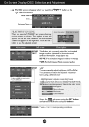
... text images (Word processing etc.) USER User You can save or restore the adjusted value even when using a different envir To adjust the USER sub-menu function, Press the SET Button USER BRIGHTNESS ACE 1 RCM 2 SAVE ... (Brightness): Adjusts screen brightness. ...ACE(Adaptive Clarity Enhancer): Selects the clarity mode. ...RCM(Real Color Management): Selects the color mode. 0 Not applied 1 Green enhance 2 Flesh tone 3 Color Enhance Select the SAVE sub-menu using the SET button and save the YES value using the buttons. The applied screen...
... text images (Word processing etc.) USER User You can save or restore the adjusted value even when using a different envir To adjust the USER sub-menu function, Press the SET Button USER BRIGHTNESS ACE 1 RCM 2 SAVE ... (Brightness): Adjusts screen brightness. ...ACE(Adaptive Clarity Enhancer): Selects the clarity mode. ...RCM(Real Color Management): Selects the color mode. 0 Not applied 1 Green enhance 2 Flesh tone 3 Color Enhance Select the SAVE sub-menu using the SET button and save the YES value using the buttons. The applied screen...
Owner's Manual (English)
Page 17
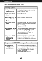
... display is connected display connected? frequency range of this manual and configure your display is not connected. Do you see a "OSD LOCKED" message on and the • Adjust the brightness and the contrast. A16 G Do you see a "CHECK SIGNAL CABLE" message on PC (video card) is out of the • Check and see if the power cord is in power saving mode, try again. G Is the power on the screen? No image appears G Is the power cord of horizontal or vertical the screen...
... display is connected display connected? frequency range of this manual and configure your display is not connected. Do you see a "OSD LOCKED" message on and the • Adjust the brightness and the contrast. A16 G Do you see a "CHECK SIGNAL CABLE" message on PC (video card) is out of the • Check and see if the power cord is in power saving mode, try again. G Is the power on the screen? No image appears G Is the power cord of horizontal or vertical the screen...
Owner's Manual (English)
Page 18
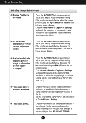
... screen display. • Check Control Panel --> Display --> Settings and see if the frequency or the resolution were changed. Settings. • Check if the screen is set to interlace mode and if yes, change it to the recommend resolution. • Make sure the power voltage is high enough, It has to the ideal setting. Set the color setting higher than 24 bits (true color) at Control Panel - Troubleshooting Display image is incorrect G Display Position is incorrect. • Press the AUTO/SET button to automatically adjust your display image...
... screen display. • Check Control Panel --> Display --> Settings and see if the frequency or the resolution were changed. Settings. • Check if the screen is set to interlace mode and if yes, change it to the recommend resolution. • Make sure the power voltage is high enough, It has to the ideal setting. Set the color setting higher than 24 bits (true color) at Control Panel - Troubleshooting Display image is incorrect G Display Position is incorrect. • Press the AUTO/SET button to automatically adjust your display image...
Owner's Manual (English)
Page 19
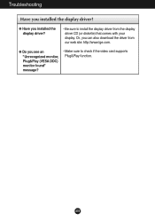
Or, you installed the display driver? Troubleshooting Have you can also download the driver from the display driver CD (or diskette) that comes with your display. G Do you installed the display driver? • Be sure to check if the video card supports Plug&Play function. A18 G Have you see an "Unrecognized monitor, Plug&Play (VESA DDC) monitor found" message? • Make sure to install the display driver from our web site: http://www.lge.com.
Or, you installed the display driver? Troubleshooting Have you can also download the driver from the display driver CD (or diskette) that comes with your display. G Do you installed the display driver? • Be sure to check if the video card supports Plug&Play function. A18 G Have you see an "Unrecognized monitor, Plug&Play (VESA DDC) monitor found" message? • Make sure to install the display driver from our web site: http://www.lge.com.
Owner's Manual (English)
Page 20
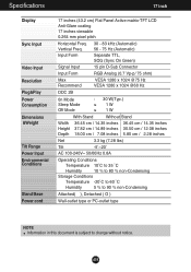
...˚C to 60 ˚C Humidity 5 % to 90 % non-Condensing Attached( ), Detached ( O ) Wall-outlet type or PC-outlet type NOTE Information in this document is subject to change without notice. A19 Vertical Freq. Specifications 17 inch Display Sync Input Video Input Resolution Plug&Play Power Consumption Dimensions &Weight Tilt Range Power Input Environmental Conditions Stand Base Power cord 17 inches (43.2 cm) Flat Panel Active matrix-TFT LCD Anti-Glare coating 17 inches viewable 0.264 mm pixel pitch Horizontal Freq.
...˚C to 60 ˚C Humidity 5 % to 90 % non-Condensing Attached( ), Detached ( O ) Wall-outlet type or PC-outlet type NOTE Information in this document is subject to change without notice. A19 Vertical Freq. Specifications 17 inch Display Sync Input Video Input Resolution Plug&Play Power Consumption Dimensions &Weight Tilt Range Power Input Environmental Conditions Stand Base Power cord 17 inches (43.2 cm) Flat Panel Active matrix-TFT LCD Anti-Glare coating 17 inches viewable 0.264 mm pixel pitch Horizontal Freq.

Owner's Manual (English)
Page 21
Specifications 19 inch Display Sync Input Video Input Resolution Plug&Play Power Consumption Dimensions &Weight Tilt Range Power Input Environmental Conditions Stand Base Power cord 19 inches (48.19 cm) Flat Panel Active matrix-TFT LCD Anti-Glare coating 19 inches viewable 0.294 mm pixel pitch Horizontal Freq. Input Form 30 - 83 kHz (Automatic) 56 - 75 Hz (Automatic) Separate TTL, SOG (Sync On Green) Signal Input 15 pin D-Sub Connector Input Form RGB Analog (0.7 Vp-p/ 75 ohm) Max Recommend VESA 1280 x 1024 @75 Hz VESA 1280 x 1024 @60 Hz DDC 2B 0n...
Specifications 19 inch Display Sync Input Video Input Resolution Plug&Play Power Consumption Dimensions &Weight Tilt Range Power Input Environmental Conditions Stand Base Power cord 19 inches (48.19 cm) Flat Panel Active matrix-TFT LCD Anti-Glare coating 19 inches viewable 0.294 mm pixel pitch Horizontal Freq. Input Form 30 - 83 kHz (Automatic) 56 - 75 Hz (Automatic) Separate TTL, SOG (Sync On Green) Signal Input 15 pin D-Sub Connector Input Form RGB Analog (0.7 Vp-p/ 75 ohm) Max Recommend VESA 1280 x 1024 @75 Hz VESA 1280 x 1024 @60 Hz DDC 2B 0n...
Owner's Manual (English)
Page 23
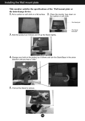
Pull out the Stand to remove. Installing the Wall mount plate This monitor satisfies the specifications of the Wall mount plate or the interchange device. 1. 2. The Stand base part 4. Put a cushion or soft cloth on the cushion or soft cloth. Change your hold on the product as it follows and turn the Stand Base in the arrow direction until you hear a "click." 5. The Head part 3. Place the monitor face down on a flat surface. Hold the product as it follows and lift up the Stand slightly. A22
Pull out the Stand to remove. Installing the Wall mount plate This monitor satisfies the specifications of the Wall mount plate or the interchange device. 1. 2. The Stand base part 4. Put a cushion or soft cloth on the cushion or soft cloth. Change your hold on the product as it follows and turn the Stand Base in the arrow direction until you hear a "click." 5. The Head part 3. Place the monitor face down on a flat surface. Hold the product as it follows and lift up the Stand slightly. A22


