User Guide
Page 2
... installation. If the power cable is OFF. Never leave the display ON when leaving the house. Keep children from the wall outlet. Some internal parts carry hazardous voltages. On Safety Use only the power cord supplied with your dealer. So are no user serviceable components inside , even when the power is faulty in potential eletrical shock or fire hazards. There are frayed power cords and broken plugs...
... installation. If the power cable is OFF. Never leave the display ON when leaving the house. Keep children from the wall outlet. Some internal parts carry hazardous voltages. On Safety Use only the power cord supplied with your dealer. So are no user serviceable components inside , even when the power is faulty in potential eletrical shock or fire hazards. There are frayed power cords and broken plugs...

User Guide
Page 3
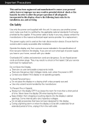
... LCD screen with your LCD display. On Repacking Do not throw away the carton and packing materials. On Disposal The fluorescent lamp used under any mode except the recommended resolution, some scaled or processed images may cause some afterimages. Use a slightly damp (not wet) cloth. A2 However, this display near water such as Red, Green or Blue spots on the screen. Important Precautions On Installation...
... LCD screen with your LCD display. On Repacking Do not throw away the carton and packing materials. On Disposal The fluorescent lamp used under any mode except the recommended resolution, some scaled or processed images may cause some afterimages. Use a slightly damp (not wet) cloth. A2 However, this display near water such as Red, Green or Blue spots on the screen. Important Precautions On Installation...
User Guide
Page 4
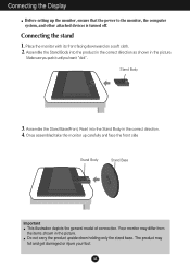
... Stand Base(Front, Rear) into the product in the correct direction as shown in the picture. Connecting the stand 1. REAR REAR Connecting the Display Before setting up carefully and face the front side Important This illustration depicts the general model of connection. Once assembled take the monitor up the monitor, ensure that the power to the monitor, the computer system, and other attached devices is turned...
... Stand Base(Front, Rear) into the product in the correct direction as shown in the picture. Connecting the stand 1. REAR REAR Connecting the Display Before setting up carefully and face the front side Important This illustration depicts the general model of connection. Once assembled take the monitor up the monitor, ensure that the power to the monitor, the computer system, and other attached devices is turned...

User Guide
Page 5
The Stand base part 4. Pull out the Stand to remove. The Head part 3. Place the monitor face down on a flat surface. Hold the product as it follows and lift up the Stand slightly. Connecting the Display To remove the Stand: 1. 2. A4 Put a cushion or soft cloth on the cushion or soft cloth. Change your hold on the product as it follows and turn the Stand Base in the arrow direction until you hear a "click." 5.
The Stand base part 4. Pull out the Stand to remove. The Head part 3. Place the monitor face down on a flat surface. Hold the product as it follows and lift up the Stand slightly. Connecting the Display To remove the Stand: 1. 2. A4 Put a cushion or soft cloth on the cushion or soft cloth. Change your hold on the product as it follows and turn the Stand Base in the arrow direction until you hear a "click." 5.
User Guide
Page 6
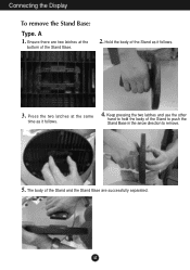
Connecting the Display To remove the Stand Base: Type. Press the two latches at the bottom of the Stand and the Stand Base are two latches at the same time as it follows. 4. A 1. Ensure there are successfully separated. Keep pressing the two latches and use the other hand to hold the body of the Stand as it follows. 3. The body of the Stand Base. 2. A5 Hold the body of the Stand to push the Stand Base in the arrow direction to remove. 5.
Connecting the Display To remove the Stand Base: Type. Press the two latches at the bottom of the Stand and the Stand Base are two latches at the same time as it follows. 4. A 1. Ensure there are successfully separated. Keep pressing the two latches and use the other hand to hold the body of the Stand as it follows. 3. The body of the Stand Base. 2. A5 Hold the body of the Stand to push the Stand Base in the arrow direction to remove. 5.
User Guide
Page 7
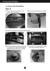
Put the Stand Base on a flat surface and pull up the body of the Stand and the Stand Base are four latches at the bottom of the Stand Base. 2.Hold the body of the Stand as it follows. 3. A6 Press the four latches individually toward each end. 4. The body of the Stand while holding the Stand Base with the other hand. B 1. Ensure there are successfully separated. to remove. 5. Connecting the Display To remove the Stand Base: Type.
Put the Stand Base on a flat surface and pull up the body of the Stand and the Stand Base are four latches at the bottom of the Stand Base. 2.Hold the body of the Stand as it follows. 3. A6 Press the four latches individually toward each end. 4. The body of the Stand while holding the Stand Base with the other hand. B 1. Ensure there are successfully separated. to remove. 5. Connecting the Display To remove the Stand Base: Type.
User Guide
Page 8
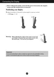
.... Adjust the position of the panel in between the head of the monitor should not exceed 5 degrees. A7 You can hurt your display 1. Connecting the Display Before setting up the monitor, ensure that the power to the monitor, the computer system, and other attached devices is recommended that in order to maintain an ergonomic and comfortable viewing position, the forward tilt angle of the monitor...
.... Adjust the position of the panel in between the head of the monitor should not exceed 5 degrees. A7 You can hurt your display 1. Connecting the Display Before setting up the monitor, ensure that the power to the monitor, the computer system, and other attached devices is recommended that in order to maintain an ergonomic and comfortable viewing position, the forward tilt angle of the monitor...
User Guide
Page 9
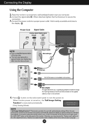
... display. 2 Power Cord Signal Cable Analog signal Digital signal D-sub DVI NOTE Varies according to a 15 pin 2 row connector. 4. Connect the power cord into a proper power outlet that this function automatically adjusts the display to change the 15 pin high density (3 row) D-sub VGA connector on . your computer. 2. This rear view represents a general model; However, be aware that is needed to optimal settings for individual input signals. Press button on the side switch panel to turn the power on the supplied cable to model. Connecting the Display Using...
... display. 2 Power Cord Signal Cable Analog signal Digital signal D-sub DVI NOTE Varies according to a 15 pin 2 row connector. 4. Connect the power cord into a proper power outlet that this function automatically adjusts the display to change the 15 pin high density (3 row) D-sub VGA connector on . your computer. 2. This rear view represents a general model; However, be aware that is needed to optimal settings for individual input signals. Press button on the side switch panel to turn the power on the supplied cable to model. Connecting the Display Using...
User Guide
Page 10
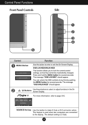
... seconds. SOURCE Hot key Use this button to enter or exit the On Screen Display. For more information, refer to the display. A9 OSD LOCKED/UNLOCKED This function allows you to select or adjust functions in the On Screen Display. The message "OSD LOCKED" should appear. Control Panel Functions Front Panel Controls Side Control MENU Button Function Use this button to make D-Sub or DVI connector active. The message "OSD UNLOCKED" should appear. Buttons Use these buttons to lock the current control settings, so...
... seconds. SOURCE Hot key Use this button to enter or exit the On Screen Display. For more information, refer to the display. A9 OSD LOCKED/UNLOCKED This function allows you to select or adjust functions in the On Screen Display. The message "OSD LOCKED" should appear. Control Panel Functions Front Panel Controls Side Control MENU Button Function Use this button to make D-Sub or DVI connector active. The message "OSD UNLOCKED" should appear. Buttons Use these buttons to lock the current control settings, so...
User Guide
Page 11
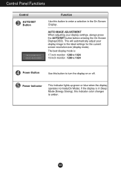
...the AUTO/SET button before entering the On Screen Display(OSD). A10 Power Indicator This Indicator lights up green or blue when the display operates normally(On Mode). The best display mode is in the On Screen Display. AUTO IMAGE ADJUSTMENT When adjusting your display image to enter a selection in Sleep Mode (Energy Saving), this button to amber. If the display is 17 inch monitor : 1280 x 1024 19 inch monitor : 1280 x 1024 Power Button Use this indicator color changes to turn the display on or off. Control Panel Functions Control AUTO/SET Button Function Use this button to...
...the AUTO/SET button before entering the On Screen Display(OSD). A10 Power Indicator This Indicator lights up green or blue when the display operates normally(On Mode). The best display mode is in the On Screen Display. AUTO IMAGE ADJUSTMENT When adjusting your display image to enter a selection in Sleep Mode (Energy Saving), this button to amber. If the display is 17 inch monitor : 1280 x 1024 19 inch monitor : 1280 x 1024 Power Button Use this indicator color changes to turn the display on or off. Control Panel Functions Control AUTO/SET Button Function Use this button to...
User Guide
Page 13
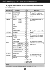
... adjust the brightness, contrast and gamma of the screen COLOR POSITION PRESET sRGB 6500K 9300K RED GREEN BLUE HORIZONTAL VERTICAL To customize the color of the screen To adjust the position of the screen CLOCK TRACKING PHASE SHARPNESS To improve the clarity and stability, sharpness of the screen SETUP LANGUAGE OSD HORIZONTAL POSITION VERTICAL To customize the screen status for a user's operating environment FLATRON F-ENGINE WHITE BALANCE POWER INDICATOR FACTORY RESET MOVIE / TEXT USER NORMAL To select or customize desired image settings : Adjustable A : Analog Input D : Digital...
... adjust the brightness, contrast and gamma of the screen COLOR POSITION PRESET sRGB 6500K 9300K RED GREEN BLUE HORIZONTAL VERTICAL To customize the color of the screen To adjust the position of the screen CLOCK TRACKING PHASE SHARPNESS To improve the clarity and stability, sharpness of the screen SETUP LANGUAGE OSD HORIZONTAL POSITION VERTICAL To customize the screen status for a user's operating environment FLATRON F-ENGINE WHITE BALANCE POWER INDICATOR FACTORY RESET MOVIE / TEXT USER NORMAL To select or customize desired image settings : Adjustable A : Analog Input D : Digital...
User Guide
Page 14
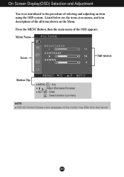
A13 Press the MENU Button, then the main menu of selecting and adjusting an item using the OSD system. Menu Name PICTURE Icons Sub-menus Button Tip MENU : Exit : Adjust (Decrease/Increase) SET : Enter : Select another sub-menu NOTE OSD (On Screen Display) menu languages on the Menu. On Screen Display(OSD) Selection and Adjustment You were introduced to the procedure of the OSD appears. Listed below are the icons, icon names, and icon descriptions of the all items shown on the monitor may differ from the manual.
A13 Press the MENU Button, then the main menu of selecting and adjusting an item using the OSD system. Menu Name PICTURE Icons Sub-menus Button Tip MENU : Exit : Adjust (Decrease/Increase) SET : Enter : Select another sub-menu NOTE OSD (On Screen Display) menu languages on the Menu. On Screen Display(OSD) Selection and Adjustment You were introduced to the procedure of the OSD appears. Listed below are the icons, icon names, and icon descriptions of the all items shown on the monitor may differ from the manual.
User Guide
Page 15
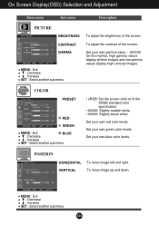
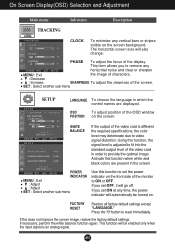
...• 9300K: Slightly bluish white. On Screen Display(OSD) Selection and Adjustment Main menu Sub menu Description PICTURE PICTURE BRIGHTNESS CONTRAST GAMMA MENU : Exit : Decrease : Increase SET : Select another sub-menu To adjust the brightness of the screen. COLOR COLOR PRESET RED GREEN MENU : Exit BLUE : Decrease : Increase SET : Select another sub-menu A14 Set your own green color levels. Set your own red color levels. POSITION POSITION HORIZONTAL VERTICAL To move image up and down. To adjust the contrast of the screen. To move image left and right.
...• 9300K: Slightly bluish white. On Screen Display(OSD) Selection and Adjustment Main menu Sub menu Description PICTURE PICTURE BRIGHTNESS CONTRAST GAMMA MENU : Exit : Decrease : Increase SET : Select another sub-menu To adjust the brightness of the screen. COLOR COLOR PRESET RED GREEN MENU : Exit BLUE : Decrease : Increase SET : Select another sub-menu A14 Set your own green color levels. Set your own red color levels. POSITION POSITION HORIZONTAL VERTICAL To move image up and down. To adjust the contrast of the screen. To move image left and right.
User Guide
Page 16
... required specifications, the color level may deteriorate due to video signal distortion. A15 The horizontal screen size will go off. OSD To adjust position of the screen. If you set ON at any horizontal noise and clear or sharpen MENU : Exit : Decrease the image of characters. : Increase SHARPNESS To adjust the clearness of the OSD window POSITION on the screen background. FACTORY RESET Restore all factory default settings except "LANGUAGE." If this function to set the power indicator...
... required specifications, the color level may deteriorate due to video signal distortion. A15 The horizontal screen size will go off. OSD To adjust position of the screen. If you set ON at any horizontal noise and clear or sharpen MENU : Exit : Decrease the image of characters. : Increase SHARPNESS To adjust the clearness of the OSD window POSITION on the screen background. FACTORY RESET Restore all factory default settings except "LANGUAGE." If this function to set the power indicator...
User Guide
Page 17
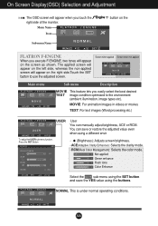
... text images (Word processing etc.) USER User You can save or restore the adjusted value even when using a different envir To adjust the USER sub-menu function, Press the SET Button USER BRIGHTNESS ACE 1 RCM 2 SAVE ... (Brightness): Adjusts screen brightness. ...ACE(Adaptive Clarity Enhancer): Selects the clarity mode. ...RCM(Real Color Management): Selects the color mode. 0 Not applied 1 Green enhance 2 Flesh tone 3 Color Enhance Select the SAVE sub-menu using the SET button and save the YES value using the buttons. Screen when applied Screen...
... text images (Word processing etc.) USER User You can save or restore the adjusted value even when using a different envir To adjust the USER sub-menu function, Press the SET Button USER BRIGHTNESS ACE 1 RCM 2 SAVE ... (Brightness): Adjusts screen brightness. ...ACE(Adaptive Clarity Enhancer): Selects the clarity mode. ...RCM(Real Color Management): Selects the color mode. 0 Not applied 1 Green enhance 2 Flesh tone 3 Color Enhance Select the SAVE sub-menu using the SET button and save the YES value using the buttons. Screen when applied Screen...
User Guide
Page 18
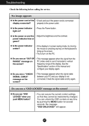
... the Power button. You can secure the current control settings, so that they cannot be inadvertently changed. power indicator blue or green? ● Is the power indicator amber? • If the display is connected display connected? See the 'Specifications' section of this manual and configure your display is out of horizontal or vertical the screen? Do you see a "OSD LOCKED" message on and the • Adjust the brightness and the contrast. A17 Troubleshooting Check the following...
... the Power button. You can secure the current control settings, so that they cannot be inadvertently changed. power indicator blue or green? ● Is the power indicator amber? • If the display is connected display connected? See the 'Specifications' section of this manual and configure your display is out of horizontal or vertical the screen? Do you see a "OSD LOCKED" message on and the • Adjust the brightness and the contrast. A17 Troubleshooting Check the following...
User Guide
Page 19
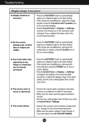
... screen blinks. • Check if the signal cable is properly connected and use a screwdriver to the ideal setting. Troubleshooting Display image is incorrect ● Display Position is incorrect. • Press the AUTO/SET button to automatically adjust your display image to fasten if necessary. • Make sure the video card is properly inserted in the slot. • Set the color setting higher than 24 bits (true color) at Control Panel - If the results are unsatisfactory, decrease the horizontal bars using...
... screen blinks. • Check if the signal cable is properly connected and use a screwdriver to the ideal setting. Troubleshooting Display image is incorrect ● Display Position is incorrect. • Press the AUTO/SET button to automatically adjust your display image to fasten if necessary. • Make sure the video card is properly inserted in the slot. • Set the color setting higher than 24 bits (true color) at Control Panel - If the results are unsatisfactory, decrease the horizontal bars using...
User Guide
Page 20
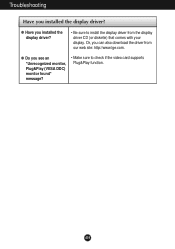
Troubleshooting Have you installed the display driver? ● Have you installed the display driver? • Be sure to check if the video card supports Plug&Play function. Or, you see an "Unrecognized monitor, Plug&Play (VESA DDC) monitor found" message? • Make sure to install the display driver from our web site: http://www.lge.com. ● Do you can also download the driver from the display driver CD (or diskette) that comes with your display. A19
Troubleshooting Have you installed the display driver? ● Have you installed the display driver? • Be sure to check if the video card supports Plug&Play function. Or, you see an "Unrecognized monitor, Plug&Play (VESA DDC) monitor found" message? • Make sure to install the display driver from our web site: http://www.lge.com. ● Do you can also download the driver from the display driver CD (or diskette) that comes with your display. A19
User Guide
Page 21
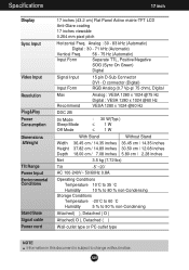
... to change without notice. Specifications 17 inch Display Sync Input Video Input Resolution Plug&Play Power Consumption Dimensions &Weight Tilt Range Power Input Environmental Conditions Stand Base Signal cable Power cord 17 inches (43.2 cm) Flat Panel Active matrix-TFT LCD Anti-Glare coating 17 inches viewable 0.264 mm pixel pitch Horizontal Freq. A20 Analog : 30 - 83 kHz (Automatic) Digital : 30 - 71 kHz (Automatic) Vertical Freq. 56 - 75 Hz (Automatic) Input Form Separate TTL, Positive/Negative SOG (Sync On Green) Digital Signal Input Input Form 15 pin D-Sub Connector DVI -
... to change without notice. Specifications 17 inch Display Sync Input Video Input Resolution Plug&Play Power Consumption Dimensions &Weight Tilt Range Power Input Environmental Conditions Stand Base Signal cable Power cord 17 inches (43.2 cm) Flat Panel Active matrix-TFT LCD Anti-Glare coating 17 inches viewable 0.264 mm pixel pitch Horizontal Freq. A20 Analog : 30 - 83 kHz (Automatic) Digital : 30 - 71 kHz (Automatic) Vertical Freq. 56 - 75 Hz (Automatic) Input Form Separate TTL, Positive/Negative SOG (Sync On Green) Digital Signal Input Input Form 15 pin D-Sub Connector DVI -
User Guide
Page 22
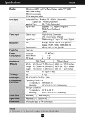
...Sync On Green) Digital Signal Input Input Form 15 pin D-Sub Connector DVI - Specifications 19 inch Display Sync Input Video Input Resolution Plug&Play Power Consumption Dimensions &Weight Tilt Range Power Input Environmental Conditions Stand Base Signal cable Power cord 19 inches (48.19 cm) Flat Panel Active matrix-TFT LCD Anti-Glare coating 19 inches viewable 0.294 mm pixel pitch Horizontal Freq. D connector (Digital) RGB Analog (0.7 Vp-p/ 75 ohm), Digital Max Recommend Analog : VESA 1280 x 1024 @75 Hz Digital : VESA 1280 x 1024 @60 Hz VESA 1280 x 1024 @60 Hz DDC 2B 0n Mode Sleep...
...Sync On Green) Digital Signal Input Input Form 15 pin D-Sub Connector DVI - Specifications 19 inch Display Sync Input Video Input Resolution Plug&Play Power Consumption Dimensions &Weight Tilt Range Power Input Environmental Conditions Stand Base Signal cable Power cord 19 inches (48.19 cm) Flat Panel Active matrix-TFT LCD Anti-Glare coating 19 inches viewable 0.294 mm pixel pitch Horizontal Freq. D connector (Digital) RGB Analog (0.7 Vp-p/ 75 ohm), Digital Max Recommend Analog : VESA 1280 x 1024 @75 Hz Digital : VESA 1280 x 1024 @60 Hz VESA 1280 x 1024 @60 Hz DDC 2B 0n Mode Sleep...


