User Manual
Page 2
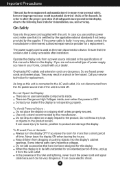
..., never touch the power cord and signal cable because it is to allow the proper operation of this display, observe the following basic rules for replacement. If the power cable is used as this display. Use only a stand recommended by the supplier. Do not throw any way, please contact the manufacturer or the nearest authorized repair service provider for this unit is easily accessible after installation...
..., never touch the power cord and signal cable because it is to allow the proper operation of this display, observe the following basic rules for replacement. If the power cable is used as this display. Use only a stand recommended by the supplier. Do not throw any way, please contact the manufacturer or the nearest authorized repair service provider for this unit is easily accessible after installation...

User Manual
Page 3
... appear as Red, Green or Blue spots on the screen. If used under any mode except the recommended resolution, some afterimages. Otherwise, it with ventilation openings in a fire hazard. If these openings are provided with both hands to move. Place the display near or over the power cord, and do not place the display where the power cord is subject to the screen and cause image burn...
... appear as Red, Green or Blue spots on the screen. If used under any mode except the recommended resolution, some afterimages. Otherwise, it with ventilation openings in a fire hazard. If these openings are provided with both hands to move. Place the display near or over the power cord, and do not place the display where the power cord is subject to the screen and cause image burn...

User Manual
Page 5
... base lock to the monitor, the computer system, and other attached devices is turned off. The product may differ from the items shown in the picture. Stand Body Stand Base 4. Assemble the Stand Body into the Stand Body in the picture. Assemble the Stand Base(Front, Rear) into the product in the correct direction as shown in the correct direction. Hinge Body Stand Body 3. Connecting the Display Before setting...
... base lock to the monitor, the computer system, and other attached devices is turned off. The product may differ from the items shown in the picture. Stand Body Stand Base 4. Assemble the Stand Body into the Stand Body in the picture. Assemble the Stand Base(Front, Rear) into the product in the correct direction as shown in the correct direction. Hinge Body Stand Body 3. Connecting the Display Before setting...

User Manual
Page 6
Place the monitor face Down on the product as it follows and turn it . 4. A5 Change your lock on the cushion or soft cloth. 3. Pull out the Stand to remove. If you can't release the stand base even the locking knob is at a release position, Please push the indicated knob down and retry it in the arrow direction. Connecting the Display Disassembling the stand 1. Put a cushion or soft cloth on aflat surface. 2.
Place the monitor face Down on the product as it follows and turn it . 4. A5 Change your lock on the cushion or soft cloth. 3. Pull out the Stand to remove. If you can't release the stand base even the locking knob is at a release position, Please push the indicated knob down and retry it in the arrow direction. Connecting the Display Disassembling the stand 1. Put a cushion or soft cloth on aflat surface. 2.

User Manual
Page 7
... recommended that in order to maintain an ergonomic and comfortable viewing position, the forward tilt angle of the panel in various ways for maximum comfort. Tilt Range : -5˚~20˚ 20 Ergonomic It is turned off. Warning: You can hurt your display 1. Adjust the position of the monitor should not exceed 5 degrees. Connecting the Display 5. Pushing the PUSH button, Take the stand base from stand body. A6
... recommended that in order to maintain an ergonomic and comfortable viewing position, the forward tilt angle of the panel in various ways for maximum comfort. Tilt Range : -5˚~20˚ 20 Ergonomic It is turned off. Warning: You can hurt your display 1. Adjust the position of the monitor should not exceed 5 degrees. Connecting the Display 5. Pushing the PUSH button, Take the stand base from stand body. A6

User Manual
Page 8
... model; Press button on the front switch panel to optimal settings for the first time, this function automatically adjusts the display to turn off the computer and product. This function provides the user with ferrite cores to improve resolution. Connect the cable as shown. A7 Power Cord Analog signal D-sub Digital signal DVI Wall-outlet type PC-outlet type Mac adapter For Apple Macintosh use shielded signal interface cables (D-sub 15 pin cable, DVI cable) with optimal display settings.When the user connects the monitor...
... model; Press button on the front switch panel to optimal settings for the first time, this function automatically adjusts the display to turn off the computer and product. This function provides the user with ferrite cores to improve resolution. Connect the cable as shown. A7 Power Cord Analog signal D-sub Digital signal DVI Wall-outlet type PC-outlet type Mac adapter For Apple Macintosh use shielded signal interface cables (D-sub 15 pin cable, DVI cable) with optimal display settings.When the user connects the monitor...

User Manual
Page 9
The message "OSD LOCKED" appears. A8 OSD LOCKED/UNLOCKED This function allows you to enter or exit from the On Screen Display. The message "OSD UNLOCKED" appears. You can unlock the OSD settings at any time by pushing the MENU button for several seconds. To lock the OSD settings, press and hold the MENU button for several seconds. Control Panel Functions Front Panel Controls Control Function MENU Button Use this button to lock the current control settings, so that these settings are not inadvertently changed.
The message "OSD LOCKED" appears. A8 OSD LOCKED/UNLOCKED This function allows you to enter or exit from the On Screen Display. The message "OSD UNLOCKED" appears. You can unlock the OSD settings at any time by pushing the MENU button for several seconds. To lock the OSD settings, press and hold the MENU button for several seconds. Control Panel Functions Front Panel Controls Control Function MENU Button Use this button to lock the current control settings, so that these settings are not inadvertently changed.

User Manual
Page 10
... Display. The default setting is used when two computers are connected to flicker. Use this button to select an icon in Sleep Mode (Energy Saving), this indicator changes to the display. Power Indicator This Indicator lights up as blue when the display is : L1742TE: 1280x1024 L1942TE: 1280x1024 Power Button Use this button to the ideal settings for the current screen resolution size (display mode). A9 AUTO IMAGE ADJUSTMENT When adjusting your display image to make D-Sub or DVI connector active. This will automatically adjust your display settings, always press the AUTO/SET...
... Display. The default setting is used when two computers are connected to flicker. Use this button to select an icon in Sleep Mode (Energy Saving), this indicator changes to the display. Power Indicator This Indicator lights up as blue when the display is : L1742TE: 1280x1024 L1942TE: 1280x1024 Power Button Use this button to the ideal settings for the current screen resolution size (display mode). A9 AUTO IMAGE ADJUSTMENT When adjusting your display image to make D-Sub or DVI connector active. This will automatically adjust your display settings, always press the AUTO/SET...
User Manual
Page 11
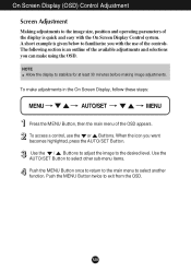
... MENU Button twice to the image size, position and operating parameters of the controls. On Screen Display (OSD) Control Adjustment Screen Adjustment Making adjustments to exit from the OSD. Use the AUTO/SET Button to select other sub-menu items. Push the MENU Button once to return to the main menu to familiarize you want becomes highlighted, press the AUTO/SET Button. A10 To access a control, use of the display is given below to select another function. A short example is quick...
... MENU Button twice to the image size, position and operating parameters of the controls. On Screen Display (OSD) Control Adjustment Screen Adjustment Making adjustments to exit from the OSD. Use the AUTO/SET Button to select other sub-menu items. Push the MENU Button once to return to the main menu to familiarize you want becomes highlighted, press the AUTO/SET Button. A10 To access a control, use of the display is given below to select another function. A short example is quick...

User Manual
Page 12
...-menu A D Reference PICTURE BRIGHTNESS CONTRAST GAMMA To adjust the brightness, contrast and gamma of the screen COLOR PRESET RED sRGB 6500K 9300K To customize the color of the screen GREEN BLUE HORIZONTAL VERTICAL TRACKING CLOCK PHASE SHARPNESS To adjust the position of the screen To improve the clarity and stability of the screen SETUP LANGUAGE OSD HORIZONTAL POSITION VERTICAL To customize the screen status for a user's operating environment WHITE BALANCE POWER INDICATOR FACTORY RESET FLATRON F-ENGINE MOVIE INTERNET USER To select or customize desired image settings...
...-menu A D Reference PICTURE BRIGHTNESS CONTRAST GAMMA To adjust the brightness, contrast and gamma of the screen COLOR PRESET RED sRGB 6500K 9300K To customize the color of the screen GREEN BLUE HORIZONTAL VERTICAL TRACKING CLOCK PHASE SHARPNESS To adjust the position of the screen To improve the clarity and stability of the screen SETUP LANGUAGE OSD HORIZONTAL POSITION VERTICAL To customize the screen status for a user's operating environment WHITE BALANCE POWER INDICATOR FACTORY RESET FLATRON F-ENGINE MOVIE INTERNET USER To select or customize desired image settings...

User Manual
Page 13
Main Menu MENU : Exit : Adjust (Decrease/Increase) SET Me: EnnuteNr ame : Select another sub-menu : Restart to the procedure of selecting and adjusting an item using the OSD system. Listed below are the icons, icon names, and icon descriptions of the OSD appears. Press the MENU Button, then the main menu of the all items shown on the monitor may differ from the manual. A12 On Screen Display(OSD) Selection and Adjustment You were introduced to select sub-menu Menu Name Button Tip Icons Sub-menus NOTE OSD (On Screen Display) menu languages on the Menu.
Main Menu MENU : Exit : Adjust (Decrease/Increase) SET Me: EnnuteNr ame : Select another sub-menu : Restart to the procedure of selecting and adjusting an item using the OSD system. Listed below are the icons, icon names, and icon descriptions of the OSD appears. Press the MENU Button, then the main menu of the all items shown on the monitor may differ from the manual. A12 On Screen Display(OSD) Selection and Adjustment You were introduced to select sub-menu Menu Name Button Tip Icons Sub-menus NOTE OSD (On Screen Display) menu languages on the Menu.

User Manual
Page 14
... green color levels. Set your own red color levels. Set your own blue color levels. To adjust the contrast of the screen. A13 Set your own gamma value. : -50/0/50 On the monitor, high gamma values display whitish images and low gamma values display blackish images. On Screen Display(OSD) Selection and Adjustment Main menu Sub menu Description PICTURE BRIGHTNESS CONTRAST GAMMA MENU : Exit : Decrease : Increase SET : Select another sub-menu • sRGB: Set the screen color to fit the SRGB standard color specification...
... green color levels. Set your own red color levels. Set your own blue color levels. To adjust the contrast of the screen. A13 Set your own gamma value. : -50/0/50 On the monitor, high gamma values display whitish images and low gamma values display blackish images. On Screen Display(OSD) Selection and Adjustment Main menu Sub menu Description PICTURE BRIGHTNESS CONTRAST GAMMA MENU : Exit : Decrease : Increase SET : Select another sub-menu • sRGB: Set the screen color to fit the SRGB standard color specification...
User Manual
Page 15
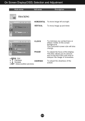
The horizontal screen size will also change. To adjust the focus of the screen. To adjust the clearness of the display. This item allows you to remove any vertical bars or stripes visible on the screen background. A14 On Screen Display(OSD) Selection and Adjustment Main menu Sub menu Description TRACKING HORIZONTAL To move image up and down. CLOCK PHASE MENU : Exit : Decrease : Increase SHARPNESS SET : Select another sub-menu To minimize any horizontal noise and clear or sharpen the image of characters. VERTICAL To move image left and right.
The horizontal screen size will also change. To adjust the focus of the screen. To adjust the clearness of the display. This item allows you to remove any vertical bars or stripes visible on the screen background. A14 On Screen Display(OSD) Selection and Adjustment Main menu Sub menu Description TRACKING HORIZONTAL To move image up and down. CLOCK PHASE MENU : Exit : Decrease : Increase SHARPNESS SET : Select another sub-menu To minimize any horizontal noise and clear or sharpen the image of characters. VERTICAL To move image left and right.

User Manual
Page 16
... sub-menu Use this does not improve the screen image, restore the factory default settings. Press the , buttons to video signal distortion. OSD To adjust position of the OSD window POSITION on the front side of the video card in the screen. If you set the power indicator on the screen. If necessary, perform the white balance function again. This function will automatically be enabled only when the input signal is an analog signal. FACTORY RESET Restore all factory default settings except "LANGUAGE...
... sub-menu Use this does not improve the screen image, restore the factory default settings. Press the , buttons to video signal distortion. OSD To adjust position of the OSD window POSITION on the front side of the video card in the screen. If you set the power indicator on the screen. If necessary, perform the white balance function again. This function will automatically be enabled only when the input signal is an analog signal. FACTORY RESET Restore all factory default settings except "LANGUAGE...

User Manual
Page 17
... best desired INTERNET image condition optimized to customer in videos or movies INTERNET: For text images (Word processing etc.) USER User You can save or restore the adjusted value even when using a different environment. ... (Brightness): Adjusts screen brightness. ...ACE(Adaptive Clarity Enhancer): Selects the clarity mode. ...RCM(Real Color Management): Selects the color mode. 0 Not applied 1 Green enhance 2 Flesh tone 3 Color Enhance Select the SAVE sub-menu using the AUTO/SET button and save the YES value using the , buttons...
... best desired INTERNET image condition optimized to customer in videos or movies INTERNET: For text images (Word processing etc.) USER User You can save or restore the adjusted value even when using a different environment. ... (Brightness): Adjusts screen brightness. ...ACE(Adaptive Clarity Enhancer): Selects the clarity mode. ...RCM(Real Color Management): Selects the color mode. 0 Not applied 1 Green enhance 2 Flesh tone 3 Color Enhance Select the SAVE sub-menu using the AUTO/SET button and save the YES value using the , buttons...

User Manual
Page 18
... current control settings, so that they cannot be inadvertently changed. light on and the • Adjust the brightness and the contrast. G Is the power on ? properly to turn on the keyboard to bring up the screen. • Try to the power outlet. Troubleshooting Check the following before calling for several seconds: the message "OSD UNLOCKED" will appear. frequency range of this manual and configure your display is in power saving mode, try...
... current control settings, so that they cannot be inadvertently changed. light on and the • Adjust the brightness and the contrast. G Is the power on ? properly to turn on the keyboard to bring up the screen. • Try to the power outlet. Troubleshooting Check the following before calling for several seconds: the message "OSD UNLOCKED" will appear. frequency range of this manual and configure your display is in power saving mode, try...

User Manual
Page 19
... the video card manufacturer. A18 If the results are unsatisfactory, decrease the horizontal bars using the H position and V position icon in the on screen display. If the results are visible. • Press the AUTO/SET button to automatically adjust your display image to the ideal setting. Important Check Control Panel --> Display --> Settings and see if the frequency or the resolution were changed. In this case, please ask to the recommend resolution. Troubleshooting Display image is incorrect G Display Position is...
... the video card manufacturer. A18 If the results are unsatisfactory, decrease the horizontal bars using the H position and V position icon in the on screen display. If the results are visible. • Press the AUTO/SET button to automatically adjust your display image to the ideal setting. Important Check Control Panel --> Display --> Settings and see if the frequency or the resolution were changed. In this case, please ask to the recommend resolution. Troubleshooting Display image is incorrect G Display Position is...

User Manual
Page 20
Troubleshooting Display image is incorrect G The screen color is mono or abnormal. • Check if the signal cable is properly connected and use a screwdriver to fasten if necessary. • Make sure the video card is set to interlace mode and if yes, change it to the recommend resolution. Do you can also download the driver from our web site: http://www.lge.com. • Make sure to install the display driver from the display driver CD...
Troubleshooting Display image is incorrect G The screen color is mono or abnormal. • Check if the signal cable is properly connected and use a screwdriver to fasten if necessary. • Make sure the video card is set to interlace mode and if yes, change it to the recommend resolution. Do you can also download the driver from our web site: http://www.lge.com. • Make sure to install the display driver from the display driver CD...

User Manual
Page 21
A20 Specifications 17 inch Display Sync Input Video Input Resolution Plug&Play Power Consumption Dimensions &Weight Tilt Range Power Input Environmental Conditions Stand Base Signal cable Power cord 17 inches (43.2 cm) Flat Panel Active matrix-TFT LCD Anti-Glare coating Visible diagonal size: 43.2 cm 0.264 mm pixel pitch Horizontal Freq. D connector (Digital) RGB Analog (0.7 Vp-p/ 75 ohm), Digital Max Recommend Analog : VESA 1280 x 1024 @75 Hz Digital : VESA 1280 x 1024 @60 Hz VESA 1280 x 1024 @60 Hz DDC 2B (Digital), DDC 2AB (Analog) On Mode Sleep Mode Off Mode : 20 W(Typ.) &#...
A20 Specifications 17 inch Display Sync Input Video Input Resolution Plug&Play Power Consumption Dimensions &Weight Tilt Range Power Input Environmental Conditions Stand Base Signal cable Power cord 17 inches (43.2 cm) Flat Panel Active matrix-TFT LCD Anti-Glare coating Visible diagonal size: 43.2 cm 0.264 mm pixel pitch Horizontal Freq. D connector (Digital) RGB Analog (0.7 Vp-p/ 75 ohm), Digital Max Recommend Analog : VESA 1280 x 1024 @75 Hz Digital : VESA 1280 x 1024 @60 Hz VESA 1280 x 1024 @60 Hz DDC 2B (Digital), DDC 2AB (Analog) On Mode Sleep Mode Off Mode : 20 W(Typ.) &#...

User Manual
Page 22
... subject to change without notice. A21 Specifications 19 inch Display Sync Input Video Input Resolution Plug&Play Power Consumption Dimensions &Weight Tilt Range Power Input Environmental Conditions Stand Base Signal cable Power cord 19 inches (48.2 cm) Flat Panel Active matrix-TFT LCD Anti-Glare coating Visible diagonal size: 48.2 cm 0.294 mm pixel pitch Horizontal Freq. Input Form Analog : 30 - 83 kHz (Automatic) Digital : 30 - 71 kHz (Automatic) 56 - 75 Hz (Automatic) Separate TTL, Positive/Negative SOG (Sync On Green) Digital Signal Input Input Form 15 pin D-Sub Connector DVI...
... subject to change without notice. A21 Specifications 19 inch Display Sync Input Video Input Resolution Plug&Play Power Consumption Dimensions &Weight Tilt Range Power Input Environmental Conditions Stand Base Signal cable Power cord 19 inches (48.2 cm) Flat Panel Active matrix-TFT LCD Anti-Glare coating Visible diagonal size: 48.2 cm 0.294 mm pixel pitch Horizontal Freq. Input Form Analog : 30 - 83 kHz (Automatic) Digital : 30 - 71 kHz (Automatic) 56 - 75 Hz (Automatic) Separate TTL, Positive/Negative SOG (Sync On Green) Digital Signal Input Input Form 15 pin D-Sub Connector DVI...


