

User Manual
Page 1
See the label attached on the product and quote this information to read the Important Precautions before using the product. User's Guide L1920P Make sure to your dealer when you require service. Keep the User's Guide(CD) in an accessible place for furture reference.
See the label attached on the product and quote this information to read the Important Precautions before using the product. User's Guide L1920P Make sure to your dealer when you require service. Keep the User's Guide(CD) in an accessible place for furture reference.
User Manual
Page 2
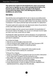
... this manual or listed on a sloping shelf unless properly secured. There are frayed power cords and broken plugs. Contact your home, consult with the unit. So are no user serviceable components inside , even when the power is easily accessible after installation. Some internal parts carry hazardous voltages. Operate the display only from dropping or pushing objects into the display's cabinet openings. Use only a stand...
... this manual or listed on a sloping shelf unless properly secured. There are frayed power cords and broken plugs. Contact your home, consult with the unit. So are no user serviceable components inside , even when the power is easily accessible after installation. Some internal parts carry hazardous voltages. Operate the display only from dropping or pushing objects into the display's cabinet openings. Use only a stand...
User Manual
Page 3
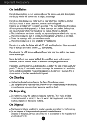
... is provided. Do not use this display near water such as Red, Green or Blue spots on the screen. Therefore, NEVER: Block the bottom ventilation slots by placing the display on the display performance. On Cleaning Unplug the display before cleaning the face of your LCD display. On Repacking Do not ... the fixed-resolution LCD panel. Place the display in a built-in a wet basement, or near or over the power cord, and do not place the display where the power cord is characteristic of this product must be carried out in its original material. Do not press the LCD screen with ...
... is provided. Do not use this display near water such as Red, Green or Blue spots on the screen. Therefore, NEVER: Block the bottom ventilation slots by placing the display on the display performance. On Cleaning Unplug the display before cleaning the face of your LCD display. On Repacking Do not ... the fixed-resolution LCD panel. Place the display in a built-in a wet basement, or near or over the power cord, and do not place the display where the power cord is characteristic of this product must be carried out in its original material. Do not press the LCD screen with ...

User Manual
Page 4
Connecting the Display Using the Computer 1. A3 Separate the back cap by pushing upward. 4. After the cables are connected, set the back cap into the groove of the upper section and reassemble by sliding its lower section downward as shown in the picture. 2. Connect the signal input cable and the power cord. (see next page) 3. Insert the back cap along the bottom grooves on both sides, holding the bottom.
Connecting the Display Using the Computer 1. A3 Separate the back cap by pushing upward. 4. After the cables are connected, set the back cap into the groove of the upper section and reassemble by sliding its lower section downward as shown in the picture. 2. Connect the signal input cable and the power cord. (see next page) 3. Insert the back cap along the bottom grooves on both sides, holding the bottom.

User Manual
Page 5
... VGA connector on the supplied cable to turn the power on the front switch panel to a 15 pin 2 row connector. 3. A4 When attached, tighten the thumbscrews to the display. Press button on . When monitor power is executed automatically. (Only Analog Mode) NOTE ' Self Image Setting Function'? Connect the signal cable. NOTE This is easily accessible and close to secure the connection. 2. Power Cord Signal Cable Digital signal Analog signal Wall-outlet type 2 1 PC-outlet type PC PC MAC Mac adapter For Apple Macintosh use...
... VGA connector on the supplied cable to turn the power on the front switch panel to a 15 pin 2 row connector. 3. A4 When attached, tighten the thumbscrews to the display. Press button on . When monitor power is executed automatically. (Only Analog Mode) NOTE ' Self Image Setting Function'? Connect the signal cable. NOTE This is easily accessible and close to secure the connection. 2. Power Cord Signal Cable Digital signal Analog signal Wall-outlet type 2 1 PC-outlet type PC PC MAC Mac adapter For Apple Macintosh use...
User Manual
Page 6
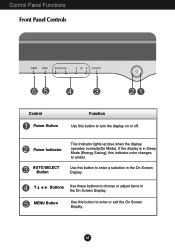
Power Indicator AUTO/SELECT Button This Indicator lights up blue when the display operates normally(On Mode). Control Panel Functions Front Panel Controls Control Power Button Function Use this button to enter or exit the On Screen Display. Buttons Use these buttons to choose or adjust items in Sleep Mode (Energy Saving), this button to enter a selection in the On Screen Display. MENU Button Use this button to amber. A5 If the display is in the On Screen Display. Use this indicator color changes to turn the display on or off.
Power Indicator AUTO/SELECT Button This Indicator lights up blue when the display operates normally(On Mode). Control Panel Functions Front Panel Controls Control Power Button Function Use this button to enter or exit the On Screen Display. Buttons Use these buttons to choose or adjust items in Sleep Mode (Energy Saving), this button to enter a selection in the On Screen Display. MENU Button Use this button to amber. A5 If the display is in the On Screen Display. Use this indicator color changes to turn the display on or off.

User Manual
Page 7
... Contrast and Brightness adjustment. This will appear. MENU OSD LOCKED/UNLOCKED : MENU This function allows you easily select the best desired image condition optimized to the display. Control Panel Functions Control Direct Access Function AUTO IMAGE ADJUSTMENT When adjusting your display image to the ideal settings for the current screen resolution size (display mode).The best display mode is 19 inch monitor : 1280x1024 PICTURE DAY NIGHT This feature lets you to secure the current control settings, so that they cannot be inadvertently changed. The display automatically...
... Contrast and Brightness adjustment. This will appear. MENU OSD LOCKED/UNLOCKED : MENU This function allows you easily select the best desired image condition optimized to the display. Control Panel Functions Control Direct Access Function AUTO IMAGE ADJUSTMENT When adjusting your display image to the ideal settings for the current screen resolution size (display mode).The best display mode is 19 inch monitor : 1280x1024 PICTURE DAY NIGHT This feature lets you to secure the current control settings, so that they cannot be inadvertently changed. The display automatically...
User Manual
Page 8
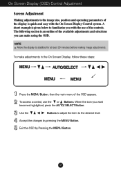
... section is quick and easy with the On Screen Display Control system. To access a control, use of the display is an outline of the OSD appears. When the icon you with the use the or Buttons. A short example is given below to familiarize you want becomes highlighted, press the AUTO/ SELECT Button. Accept the changes by Pressing the MENU Button. On Screen Display (OSD) Control Adjustment Screen Adjustment Making adjustments to the image size, position and operating...
... section is quick and easy with the On Screen Display Control system. To access a control, use of the display is an outline of the OSD appears. When the icon you with the use the or Buttons. A short example is given below to familiarize you want becomes highlighted, press the AUTO/ SELECT Button. Accept the changes by Pressing the MENU Button. On Screen Display (OSD) Control Adjustment Screen Adjustment Making adjustments to the image size, position and operating...

User Manual
Page 9
... control, adjustment, and setting menus. A8 Main menu Sub menu A PICTURE COLOR BRIGHTNESS CONTRAST GAMMA PRESET 6500K 9300K RED GREEN BLUE POSITION HORIZONTAL VERTICAL TRACKING CLOCK PHASE SETUP LANGUAGE OSD HORIZONTAL POSITION VERTICAL WHITE BALANCE POWER INDICATOR FACTORY RESET D Reference To adjust the brightness, contrast and gamma of the screen To customize the color of the screen To adjust the position of the screen To improve the clarity and stability of the screen To customize the screen status for a user's operating environment : Adjustable A : Analog Input D : Digital...
... control, adjustment, and setting menus. A8 Main menu Sub menu A PICTURE COLOR BRIGHTNESS CONTRAST GAMMA PRESET 6500K 9300K RED GREEN BLUE POSITION HORIZONTAL VERTICAL TRACKING CLOCK PHASE SETUP LANGUAGE OSD HORIZONTAL POSITION VERTICAL WHITE BALANCE POWER INDICATOR FACTORY RESET D Reference To adjust the brightness, contrast and gamma of the screen To customize the color of the screen To adjust the position of the screen To improve the clarity and stability of the screen To customize the screen status for a user's operating environment : Adjustable A : Analog Input D : Digital...

User Manual
Page 10
... screen. To adjust the brightness and contrast of the screen OSD Adjust Description PICTURE BRIGHTNESS To adjust the brightness of selecting and adjusting an item using the OSD system. NOTE OSD (On Screen Display) menu languages on the Menu. To customize the color of the screen. MENU Vertical Position To move image left and right. A9 CONTRAST To adjust the contrast of the screen OSD Adjust COLOR Description PRESET 6500K/9300K Select the screen color. • 6500K: Slightly reddish white. • 9300K: Slightly bluish white. BLUE To adjust the position...
... screen. To adjust the brightness and contrast of the screen OSD Adjust Description PICTURE BRIGHTNESS To adjust the brightness of selecting and adjusting an item using the OSD system. NOTE OSD (On Screen Display) menu languages on the Menu. To customize the color of the screen. MENU Vertical Position To move image left and right. A9 CONTRAST To adjust the contrast of the screen OSD Adjust COLOR Description PRESET 6500K/9300K Select the screen color. • 6500K: Slightly reddish white. • 9300K: Slightly bluish white. BLUE To adjust the position...

User Manual
Page 11
... Screen Display(OSD) Selection and Adjustment To improve the clarity and stability of the video card is different the required specifications, the color level may deteriorate due to video signal distortion. Press the button to provide the optimal image. If you to remove any vertical bars or stripes visible on the screen background.The horizontal screen size will be turned on the screen. To adjust the focus of the OSD window on . SETUP MENU MENU OSDPOSITION To adjust position...
... Screen Display(OSD) Selection and Adjustment To improve the clarity and stability of the video card is different the required specifications, the color level may deteriorate due to video signal distortion. Press the button to provide the optimal image. If you to remove any vertical bars or stripes visible on the screen background.The horizontal screen size will be turned on the screen. To adjust the focus of the OSD window on . SETUP MENU MENU OSDPOSITION To adjust position...

User Manual
Page 12
... power cord is out of horizontal or vertical frequency range of the display. Is the power indicator light on and the power indicator blue or green? Is the power indicator amber? Do you see an "OUT OF RANGE" message on the keyboard to bring up the screen. Try to the power outlet. This message appears when the signal from the PC (video card) is connected properly to turn on the screen? Check the signal cable...
... power cord is out of horizontal or vertical frequency range of the display. Is the power indicator light on and the power indicator blue or green? Is the power indicator amber? Do you see an "OUT OF RANGE" message on the keyboard to bring up the screen. Try to the power outlet. This message appears when the signal from the PC (video card) is connected properly to turn on the screen? Check the signal cable...

User Manual
Page 13
... the video card to the ideal setting. Press the AUTO/SELECT button to automatically adjust your display image to the ideal setting. Settings. The screen color is incorrect. Troubleshooting Display image is incorrect Display Position is mono or abnormal. Check if the screen is properly inserted in any image or characters are visible. Press the AUTO/SELECT button to automatically adjust your display image to the ideal setting. Check Control Panel --> Display --> Settings and see if the frequency or the resolution were changed. Set the color setting...
... the video card to the ideal setting. Press the AUTO/SELECT button to automatically adjust your display image to the ideal setting. Settings. The screen color is incorrect. Troubleshooting Display image is incorrect Display Position is mono or abnormal. Check if the screen is properly inserted in any image or characters are visible. Press the AUTO/SELECT button to automatically adjust your display image to the ideal setting. Check Control Panel --> Display --> Settings and see if the frequency or the resolution were changed. Set the color setting...

User Manual
Page 14
... display driver? USB function USB function cannot be setup. A13 Check if the USB cable is correctly connected. Make sure to install the display driver from our web site: http://www.lge.com. Be sure to check if the video card supports Plug&Play function. Troubleshooting Have you see an "Unrecognized monitor, Plug&Play (VESA DDC) monitor found" message? Check if the PC and OS are USB compliant. Have you can also download the driver from the display driver...
... display driver? USB function USB function cannot be setup. A13 Check if the USB cable is correctly connected. Make sure to install the display driver from our web site: http://www.lge.com. Be sure to check if the video card supports Plug&Play function. Troubleshooting Have you see an "Unrecognized monitor, Plug&Play (VESA DDC) monitor found" message? Check if the PC and OS are USB compliant. Have you can also download the driver from the display driver...

User Manual
Page 15
...;C to 60 ˚C Humidity 5 % to 95 % non-Condensing Attached( O ), Detached ( ) Attached( ), Detached ( O ) Wall-outlet type or PC-outlet type NOTE Information in this document is subject to change without notice. A14 Specifications Display Sync Input Video Input Resolution Plug&Play Power Consumption Dimensions &Weight (with tilt stand) Tilt Range Power Input Environmental Conditions Tilt Stand Signal cable Power cord 19 inches (48.18cm) Flat Panel Active matrix-TFT LCD Anti-Glare coating 19 inches viewable 0.294 mm pixel pitch Horizontal Freq.
...;C to 60 ˚C Humidity 5 % to 95 % non-Condensing Attached( O ), Detached ( ) Attached( ), Detached ( O ) Wall-outlet type or PC-outlet type NOTE Information in this document is subject to change without notice. A14 Specifications Display Sync Input Video Input Resolution Plug&Play Power Consumption Dimensions &Weight (with tilt stand) Tilt Range Power Input Environmental Conditions Tilt Stand Signal cable Power cord 19 inches (48.18cm) Flat Panel Active matrix-TFT LCD Anti-Glare coating 19 inches viewable 0.294 mm pixel pitch Horizontal Freq.
User Manual
Page 16
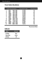
Specifications Preset Modes (Resolution) Display Modes (Resolution) 1 VGA 640 x 350 2 VGA 720 x 400 3 VGA 640 x 480 4 VESA 640 x 480 5 VESA 800 x 600 6 VESA 800 x 600 7 MAC 832 x 624 8 VESA 1024 x 768 9 VESA 1024 x 768 10 MAC 1152 x 870 11 VESA 1152 x 900 *12 VESA 1280 x 1024 13 VESA 1280 x 1024 Horizontal Freq. (kHz) 31.469 31.468 31.469 37.500 37.879 46.875 49.725 48.363 60.023 68.681 61.805 63.981 79.976 Vertical Freq. (Hz) 70 70 60 75 60 75 75 60 75 75 65 60 75 Indicator Mode On Mode Sleep Mode Off Mode LED Color Blue Amber Off *Recommend Mode A15
Specifications Preset Modes (Resolution) Display Modes (Resolution) 1 VGA 640 x 350 2 VGA 720 x 400 3 VGA 640 x 480 4 VESA 640 x 480 5 VESA 800 x 600 6 VESA 800 x 600 7 MAC 832 x 624 8 VESA 1024 x 768 9 VESA 1024 x 768 10 MAC 1152 x 870 11 VESA 1152 x 900 *12 VESA 1280 x 1024 13 VESA 1280 x 1024 Horizontal Freq. (kHz) 31.469 31.468 31.469 37.500 37.879 46.875 49.725 48.363 60.023 68.681 61.805 63.981 79.976 Vertical Freq. (Hz) 70 70 60 75 60 75 75 60 75 75 65 60 75 Indicator Mode On Mode Sleep Mode Off Mode LED Color Blue Amber Off *Recommend Mode A15

User Manual
Page 17
... S. D. Data313 T. D. D. S. S. D. D. M. M. Data2+ 3 T. S. S. M. M. M. Data1/3 Shield 12 T. Sync.) Pin Signal(DVI-D) 16 Hot Plug Detect 17 T. M. S. S. M. S. Specifications Signal Connector Pin Assignment 1 8 9 16 17 24 DVI-D Connector Pin Signal(DVI-D) 1 T. Data22 T. Data2/4 Shield 4 T. M. S. S. D. S. D. T. S. S. M. D. Data110 T. and V. M. M. D. Data4+ 6 DDC Clock 7 DDC Data 8 Analog Vertical Sync. 9 T. D. M. Sync. D. M. Clock+ 24 T. M. D. S. S. Data3+ 14 +5V Power 15 Ground (return for +5V...
... S. D. Data313 T. D. D. S. S. D. D. M. M. Data2+ 3 T. S. S. M. M. M. Data1/3 Shield 12 T. Sync.) Pin Signal(DVI-D) 16 Hot Plug Detect 17 T. M. S. S. M. S. Specifications Signal Connector Pin Assignment 1 8 9 16 17 24 DVI-D Connector Pin Signal(DVI-D) 1 T. Data22 T. Data2/4 Shield 4 T. M. S. S. D. S. D. T. S. S. M. D. Data110 T. and V. M. M. D. Data4+ 6 DDC Clock 7 DDC Data 8 Analog Vertical Sync. 9 T. D. M. Sync. D. M. Clock+ 24 T. M. D. S. S. Data3+ 14 +5V Power 15 Ground (return for +5V...

User Manual
Page 18
Install the VESA standrad wall mounting. optional Connected to another object (stand type and wall-mounted type. VESA wall mounting Connected to a locking cable that can be purchased separately at most computer stores A17 Please the monitor on a piece of the cover base with the front side facing downward and remove the rear cap. 2. Separate the stand base using a screwdriver as shown in the picture. 4. This monitor accepts a VESA-compliant mounting interface pad.-optional) For further...
Install the VESA standrad wall mounting. optional Connected to another object (stand type and wall-mounted type. VESA wall mounting Connected to a locking cable that can be purchased separately at most computer stores A17 Please the monitor on a piece of the cover base with the front side facing downward and remove the rear cap. 2. Separate the stand base using a screwdriver as shown in the picture. 4. This monitor accepts a VESA-compliant mounting interface pad.-optional) For further...

User Manual
Page 19
... a single USB port; Even if the display is an innovation in a power saving mode, USB compliant devices will be attached it. A18 Making use of the USB compliant PC or another hub with the USB cable(enclosed). By using the USB cable. (Computer must have a USB port) 2. This is running) or unplug them to a USB compliant PC(OS) or another hub using the USB, you greater flexibility in setting up your...
... a single USB port; Even if the display is an innovation in a power saving mode, USB compliant devices will be attached it. A18 Making use of the USB compliant PC or another hub with the USB cable(enclosed). By using the USB cable. (Computer must have a USB port) 2. This is running) or unplug them to a USB compliant PC(OS) or another hub using the USB, you greater flexibility in setting up your...
User Manual
Page 20
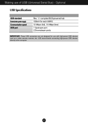
Making use with high-power USB devices such as a video camera, scanner, etc. Optional USB Specifications USB standard Downstream power supply Communication speed USB port Rev. 1.1 complied BUS-powered hub 100mA for each (MAX) 12 Mbps (full), 1.5 Mbps (low) 1 Upstream port 2 Downstream ports IMPORTANT: These USB connectors are not designed for use of USB (Universal Serial Bus) - LGE recommends connecting high-power USB devices directly to the computer A19
Making use with high-power USB devices such as a video camera, scanner, etc. Optional USB Specifications USB standard Downstream power supply Communication speed USB port Rev. 1.1 complied BUS-powered hub 100mA for each (MAX) 12 Mbps (full), 1.5 Mbps (low) 1 Upstream port 2 Downstream ports IMPORTANT: These USB connectors are not designed for use of USB (Universal Serial Bus) - LGE recommends connecting high-power USB devices directly to the computer A19


