Service Manual
Page 10
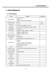
2. PERFORMANCE 2.1 H/W Feature Item Standard Battery AVG TCVR Current Standby Current Talk time Standby time Charging time RX Sensitivity TX output power GPRS compatibility SIM card type Display Status Indicator ANT EAR Phone Jack PC Synchronization Speech coding Data and Fax Vibrator Buzzer Voice Recoding C-Mic Receiver Travel Adapter Options Feature Li-Poly, 950mAh Battery Size :36.50(W)x58.50(H)x3.65(T)[mm] 280mA PERFORMANCE 2.
2. PERFORMANCE 2.1 H/W Feature Item Standard Battery AVG TCVR Current Standby Current Talk time Standby time Charging time RX Sensitivity TX output power GPRS compatibility SIM card type Display Status Indicator ANT EAR Phone Jack PC Synchronization Speech coding Data and Fax Vibrator Buzzer Voice Recoding C-Mic Receiver Travel Adapter Options Feature Li-Poly, 950mAh Battery Size :36.50(W)x58.50(H)x3.65(T)[mm] 280mA PERFORMANCE 2.
Service Manual
Page 14
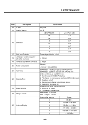
Backlight of phone set at least 200 hours: 1. At least 65 dB under below conditions: 1. 2. Normal 3 mA(@PP9) GSM900/Lvl 5 (Battery Capacity 950mA):240 min GSM900/Lvl 12(...
Backlight of phone set at least 200 hours: 1. At least 65 dB under below conditions: 1. 2. Normal 3 mA(@PP9) GSM900/Lvl 5 (Battery Capacity 950mA):240 min GSM900/Lvl 12(...
Service Manual
Page 32
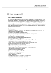
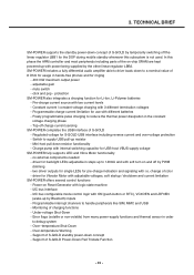
... channels for signaling • Vibrator driver with the Infineon E-GOLD+ V2 and V3 - 33 - It has been specially designed for a complete advanced GSM Edge smart phone minimizing external device count. If used with S-GOLD2 it provides all power supply functions (except for the RF PA) for usage with the Infineon SGOLD...
... channels for signaling • Vibrator driver with the Infineon E-GOLD+ V2 and V3 - 33 - It has been specially designed for a complete advanced GSM Edge smart phone minimizing external device count. If used with S-GOLD2 it provides all power supply functions (except for the RF PA) for usage with the Infineon SGOLD...
Service Manual
Page 33
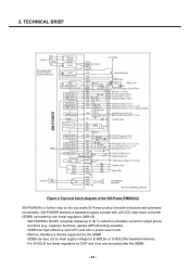
TECHNICAL BRIEF Figure 4 Top level block diagram of battery current for smart phone functions (e.g. 3. For S-GOLD two linear regulators for E-GOLD+ or S-GOLDlite baseband devices. - SM-POWER features a baseband supply concept with enhanced and optimized functionality. organizer functions, ...
TECHNICAL BRIEF Figure 4 Top level block diagram of battery current for smart phone functions (e.g. 3. For S-GOLD two linear regulators for E-GOLD+ or S-GOLDlite baseband devices. - SM-POWER features a baseband supply concept with enhanced and optimized functionality. organizer functions, ...
Service Manual
Page 34
... the standby power-down concept - I2C bus interface - Error flags (volatile or non-volatile) from many power-supply functions and thermal sensor in hands-free phones and for pre-charge indication and signaling with power being supplied by Bluetooth) inputs - no external components needed - 3.
... the standby power-down concept - I2C bus interface - Error flags (volatile or non-volatile) from many power-supply functions and thermal sensor in hands-free phones and for pre-charge indication and signaling with power being supplied by Bluetooth) inputs - no external components needed - 3.

Service Manual
Page 75
5. Trouble shooting 5.1 Trouble shooting test setup 4.000V 0.0000A Figure 51 Equipment setup Power on Trouble Check Points -Battery Voltage( Need to over 3.35V) -Power-On Key detection (PWRON signal) -Outputs of test equipment - Trouble shooting 5. Connect mobile switch cable between Communication test set and DUT when you need to the DUT for power up. - Connect PIF-UNION JIG or dummy battery to make a phone call. - Follow trouble shooting procedure 5.2 Power on all of LDOs from PMIC - 76 -
5. Trouble shooting 5.1 Trouble shooting test setup 4.000V 0.0000A Figure 51 Equipment setup Power on Trouble Check Points -Battery Voltage( Need to over 3.35V) -Power-On Key detection (PWRON signal) -Outputs of test equipment - Trouble shooting 5. Connect mobile switch cable between Communication test set and DUT when you need to the DUT for power up. - Connect PIF-UNION JIG or dummy battery to make a phone call. - Follow trouble shooting procedure 5.2 Power on all of LDOs from PMIC - 76 -

Service Manual
Page 100
... FM Radio trouble Check Points -Ear_mic_set is correctly operated as FM radio antenna (When user uses the FM radio function, Ear_mic_set must be connected in phone) -A condition of FM_Radio module soldering -FM_Radio signal is flowed correctly -Power and clock signals are supplied in U303 FM_INTn TP310 C326 L303 24p 100nH C368...
... FM Radio trouble Check Points -Ear_mic_set is correctly operated as FM radio antenna (When user uses the FM radio function, Ear_mic_set must be connected in phone) -A condition of FM_Radio module soldering -FM_Radio signal is flowed correctly -Power and clock signals are supplied in U303 FM_INTn TP310 C326 L303 24p 100nH C368...

Service Manual
Page 115
If you are going to Phone interface Cable • Power Supply or Battery • IBM compatible PC supporting RS-232 with Windows 98 or newer. 6. Download & S/W upgrade 6.1 S/W download setup 4.000V 0.0000A Figure S/W download & upgrade setup Preparation • Target terminal • PIF-Union • RS-232 Cable and PIF-UNION to use battery, the voltage of the battery should be over 3.7V for stable power supplying during S/W download. - 116 - Download & S/W upgrade 6.
If you are going to Phone interface Cable • Power Supply or Battery • IBM compatible PC supporting RS-232 with Windows 98 or newer. 6. Download & S/W upgrade 6.1 S/W download setup 4.000V 0.0000A Figure S/W download & upgrade setup Preparation • Target terminal • PIF-Union • RS-232 Cable and PIF-UNION to use battery, the voltage of the battery should be over 3.7V for stable power supplying during S/W download. - 116 - Download & S/W upgrade 6.
Service Manual
Page 137
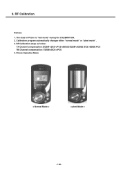
Phone Operation Mode < Normal Mode > < ptest Mode > - 138 - RF Calibration steps as follow: TX Channel compensation: EGSM->DCS->PCS->EDGE EGSM->EDGE DCS->EDGE PCS RX Channel compensation: EGSM->DCS->PCS 3. RF Calibration Notices: 1. The state of Phone is "test mode" during the CALIBRATION. 2. Calibration program automatically changes either "normal mode" or "ptest mode" . 3. 9.
Phone Operation Mode < Normal Mode > < ptest Mode > - 138 - RF Calibration steps as follow: TX Channel compensation: EGSM->DCS->PCS->EDGE EGSM->EDGE DCS->EDGE PCS RX Channel compensation: EGSM->DCS->PCS 3. RF Calibration Notices: 1. The state of Phone is "test mode" during the CALIBRATION. 2. Calibration program automatically changes either "normal mode" or "ptest mode" . 3. 9.

Service Manual
Page 139
Then Standalone Test setup is finished. - 140 - Stand-alone Test 5 For the purpose of the Standalone Test, Change the Phone to "ptest mode" and then Click the "Reset" bar. 6 Select "Non signaling" in the Quick Bar menu. 10.
Then Standalone Test setup is finished. - 140 - Stand-alone Test 5 For the purpose of the Standalone Test, Change the Phone to "ptest mode" and then Click the "Reset" bar. 6 Select "Non signaling" in the Quick Bar menu. 10.

Service Manual
Page 140
10. Stand-alone Test 2.Tx Test 1 Click "Non signaling mode" bar and then confirm "OK" text in the command line. ➀ 2 Put the number of TX Channel in the ARFCN. 3 Select "Tx" in the RF mode menu and "PCL" in the PA Level menu. 4 Finally, Click "Write All" bar and try the efficiency test of Phone. ➃ ➁ ➂ - 141 -
10. Stand-alone Test 2.Tx Test 1 Click "Non signaling mode" bar and then confirm "OK" text in the command line. ➀ 2 Put the number of TX Channel in the ARFCN. 3 Select "Tx" in the RF mode menu and "PCL" in the PA Level menu. 4 Finally, Click "Write All" bar and try the efficiency test of Phone. ➃ ➁ ➂ - 141 -

Service Manual
Page 141
Stand-alone Test 3. 10. Rx Test 1 Put the number of RX Channel in the ARFCN. 2 Select "Rx" in the RF mode menu. 3 Finally, Click "Write All" bar and try the efficiency test of Phone. ➂ ➀ ➁ 4 The Phone must be changed "normal mode" after finishing Test. 5 Change the Phone to "normal mode" and then Click the "Reset" bar. ➄ ➃ Change "normal mode " - 142 -
Stand-alone Test 3. 10. Rx Test 1 Put the number of RX Channel in the ARFCN. 2 Select "Rx" in the RF mode menu. 3 Finally, Click "Write All" bar and try the efficiency test of Phone. ➂ ➀ ➁ 4 The Phone must be changed "normal mode" after finishing Test. 5 Change the Phone to "normal mode" and then Click the "Reset" bar. ➄ ➃ Change "normal mode " - 142 -
Service Manual
Page 146
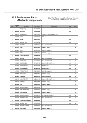
Description GSM(SLIDE) 2 AAAY00 ADDITION 3 ENSY00 CONN,SOCKET 3 MCEZ00 CASE 2 APEY00 PHONE 3 ABFZ01 BRACKET ASSY 4 MBFZ00 BRACKET 4 MTAZ00 TAPE 4 MTAZ01 TAPE 4 MTAZ02 TAPE 3 ACGM00 COVER ASSY,REAR 4 MBFZ00 BRACKET 4 MCJN00 COVER,REAR 4 MDAD00 DECO,CAMERA 4 MDAN00 DECO,...
Description GSM(SLIDE) 2 AAAY00 ADDITION 3 ENSY00 CONN,SOCKET 3 MCEZ00 CASE 2 APEY00 PHONE 3 ABFZ01 BRACKET ASSY 4 MBFZ00 BRACKET 4 MTAZ00 TAPE 4 MTAZ01 TAPE 4 MTAZ02 TAPE 3 ACGM00 COVER ASSY,REAR 4 MBFZ00 BRACKET 4 MCJN00 COVER,REAR 4 MDAD00 DECO,CAMERA 4 MDAN00 DECO,...
Service Manual
Page 166
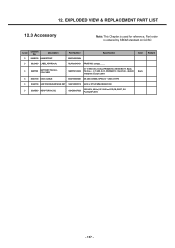
... LABEL,APPROVAL MLAA0040101 PRINTING, (empty), , , , , 3 SBPP00 BATTERY PACK,LIPOLYMER SBPP0018302 3.7 V,950 mAh,1 CELL,PRISMATIC ,KE600 BATT, Black, Pb-Free ,; ,3.7 ,950 ,0.2C ,PRISMATIC ,59x37x38 , ,BLACK ,Hardpack ,Europe Label Black 3 SGDY00 DATA CABLE SGDY0005601 DK-40G ,K8000 24PIN I/O + USB A TYPE 3 SGEY00 EAR PHONE/EAR MIKE SET SGEY0005512 U400 ,2.0T12P,MMI,REMOCOM 3 SSAD00 ADAPTOR,AC-DC...
... LABEL,APPROVAL MLAA0040101 PRINTING, (empty), , , , , 3 SBPP00 BATTERY PACK,LIPOLYMER SBPP0018302 3.7 V,950 mAh,1 CELL,PRISMATIC ,KE600 BATT, Black, Pb-Free ,; ,3.7 ,950 ,0.2C ,PRISMATIC ,59x37x38 , ,BLACK ,Hardpack ,Europe Label Black 3 SGDY00 DATA CABLE SGDY0005601 DK-40G ,K8000 24PIN I/O + USB A TYPE 3 SGEY00 EAR PHONE/EAR MIKE SET SGEY0005512 U400 ,2.0T12P,MMI,REMOCOM 3 SSAD00 ADAPTOR,AC-DC...


