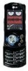
Service Manual
Page 4
... Power on Trouble 76 5.3 Charging trouble 80 5.4 LCD display trouble 82 5.5 Camera Trouble 83 5.6 Speaker trouble 86 5.7 Receiver trouble 88 5.8 Microphone trouble 90 5.9 Vibrator trouble 92 5.10 Keypad back light trouble 94 5.11 SIM card trouble 96 5.12 MicroSD trouble 98 5.13 Bluetooth trouble 99 5.14 FM Radio trouble 101 5.13 RF PART TROUBLESHOOTING ......103 6. RF Calibration 133 9.1 Test Equipment Setup 133 9.2 Calibration Steps 133 10. CIRCUIT DIAGRAM 121 8. ENGINEERING MODE 143 12. EXPLODED VIEW & REPLACEMENT PART LIST ..... 145 12.1 Exploded View 145 12.2 Replacement...
... Power on Trouble 76 5.3 Charging trouble 80 5.4 LCD display trouble 82 5.5 Camera Trouble 83 5.6 Speaker trouble 86 5.7 Receiver trouble 88 5.8 Microphone trouble 90 5.9 Vibrator trouble 92 5.10 Keypad back light trouble 94 5.11 SIM card trouble 96 5.12 MicroSD trouble 98 5.13 Bluetooth trouble 99 5.14 FM Radio trouble 101 5.13 RF PART TROUBLESHOOTING ......103 6. RF Calibration 133 9.1 Test Equipment Setup 133 9.2 Calibration Steps 133 10. CIRCUIT DIAGRAM 121 8. ENGINEERING MODE 143 12. EXPLODED VIEW & REPLACEMENT PART LIST ..... 145 12.1 Exploded View 145 12.2 Replacement...
Service Manual
Page 6
... telecommunication service of facilities accessed through or connected to prevent unauthorized use of own system. A telephone company may temporarily disconnect service as long as specifically noted in this product is faulty and possibly causing harm or interruption in Service A local telephone company may not make changes in substantial additional charges you're your telecommunications system. 1. Security Toll fraud, the unauthorized use . System users...
... telecommunication service of facilities accessed through or connected to prevent unauthorized use of own system. A telephone company may temporarily disconnect service as long as specifically noted in this product is faulty and possibly causing harm or interruption in Service A local telephone company may not make changes in substantial additional charges you're your telecommunications system. 1. Security Toll fraud, the unauthorized use . System users...
Service Manual
Page 8
... Digital Communication System dB relative to 1 milli-watt Digital Signal Processing Electrical Erasable Programmable Read-Only Memory Enhanced General Packet Radio Service Electroluminescence Electrostatic Discharge Flexible Printed Circuit Board Gaussian Minimum Shift Keying General Purpose Interface Bus General Packet Radio Service Global System for Mobile Communications International Portable User Identity Intermediate Frequency Liquid Crystal Display Low Drop Output Light Emitting Diode -9-
... Digital Communication System dB relative to 1 milli-watt Digital Signal Processing Electrical Erasable Programmable Read-Only Memory Enhanced General Packet Radio Service Electroluminescence Electrostatic Discharge Flexible Printed Circuit Board Gaussian Minimum Shift Keying General Purpose Interface Bus General Packet Radio Service Global System for Mobile Communications International Portable User Identity Intermediate Frequency Liquid Crystal Display Low Drop Output Light Emitting Diode -9-

Service Manual
Page 9
... Programmable Gain Amplifier Phase Locked Loop Public Switched Telephone Network Radio Frequency Receiving Loudness Rating Root Mean Square Real Time Clock Surface Acoustic Wave Subscriber Identity Module Sending Loudness Rating Static Random Access Memory Side Tone Masking Rating Travel Adapter Time Division Duplex Time Division Multiple Access Universal Asynchronous Receiver/Transmitter Voltage Controlled Oscillator Voltage Control Temperature Compensated Crystal Oscillator Wireless Application Protocol 8 Phase Shift Keying - 10 - 1.
... Programmable Gain Amplifier Phase Locked Loop Public Switched Telephone Network Radio Frequency Receiving Loudness Rating Root Mean Square Real Time Clock Surface Acoustic Wave Subscriber Identity Module Sending Loudness Rating Static Random Access Memory Side Tone Masking Rating Travel Adapter Time Division Duplex Time Division Multiple Access Universal Asynchronous Receiver/Transmitter Voltage Controlled Oscillator Voltage Control Temperature Compensated Crystal Oscillator Wireless Application Protocol 8 Phase Shift Keying - 10 - 1.
Service Manual
Page 10
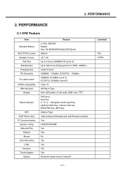
PERFORMANCE 2. PERFORMANCE 2.1 H/W Feature Item Standard Battery AVG TCVR Current Standby Current Talk time Standby time Charging time RX Sensitivity TX output power GPRS compatibility SIM card type Display Status Indicator ANT EAR Phone Jack PC Synchronization Speech coding Data and Fax Vibrator Buzzer Voice Recoding C-Mic Receiver Travel Adapter Options Feature Li-Poly, 950mAh Battery Size :36.50(W)x58.50(H)x3.65(T)[mm] 280mA 2.
PERFORMANCE 2. PERFORMANCE 2.1 H/W Feature Item Standard Battery AVG TCVR Current Standby Current Talk time Standby time Charging time RX Sensitivity TX output power GPRS compatibility SIM card type Display Status Indicator ANT EAR Phone Jack PC Synchronization Speech coding Data and Fax Vibrator Buzzer Voice Recoding C-Mic Receiver Travel Adapter Options Feature Li-Poly, 950mAh Battery Size :36.50(W)x58.50(H)x3.65(T)[mm] 280mA 2.
Service Manual
Page 14
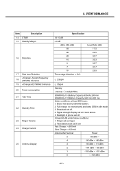
... 3 level above. 5. Ringer set as ringer. 2. Brand new and full 950mAh battery 2. Backlight of phone set off . 2. PERFORMANCE Item Description 14 STMR 15 Stability Margin 16 Distortion 17 Side tone Distortion System frequency 18 (26 MHz) tolerance 19 32.768KHz tolerance 20 Power consumption 21 Talk Time 22 Standby Time 23 Ringer Volume 24 Charge Current 25 Antenna Display Specification 13 5 dB > 6 dB...
... 3 level above. 5. Ringer set as ringer. 2. Brand new and full 950mAh battery 2. Backlight of phone set off . 2. PERFORMANCE Item Description 14 STMR 15 Stability Margin 16 Distortion 17 Side tone Distortion System frequency 18 (26 MHz) tolerance 19 32.768KHz tolerance 20 Power consumption 21 Talk Time 22 Standby Time 23 Ringer Volume 24 Charge Current 25 Antenna Display Specification 13 5 dB > 6 dB...
Service Manual
Page 21
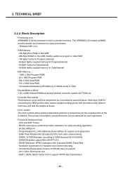
... 12 support - EDGE Modulator: 8PSK-modulation with additional phase shifters for connecting the ARM and the other master capable building blocks with the internal and external memories and with B*T=0.3 - GSM Timer Module that off-loads the CPU from radio channel timing - A5/1, A5/2, A5/3 Cipher unit - Incremental Redundancy memory for Data(internal) • DSP-Memory - 104K x 16bit Program ROM - 8k x 16bit Program...
... 12 support - EDGE Modulator: 8PSK-modulation with additional phase shifters for connecting the ARM and the other master capable building blocks with the internal and external memories and with B*T=0.3 - GSM Timer Module that off-loads the CPU from radio channel timing - A5/1, A5/2, A5/3 Cipher unit - Incremental Redundancy memory for Data(internal) • DSP-Memory - 104K x 16bit Program ROM - 8k x 16bit Program...
Service Manual
Page 22
... S/M power) - connection to 4Mbps) - Programmable clock output for Automatic Frequency Correction(AFC) - Pulse Number Modulation output for a camera - A dedicated Fas IfDA Controller supporting IrDA's SIR,MIR and FIR standards (up to control RF IC and Peripherals. 13 signals are provided switch on TX RF band select FEM control FEM control FEM control PAM Mode select - 23 - A fast display interface supporting serial...
... S/M power) - connection to 4Mbps) - Programmable clock output for Automatic Frequency Correction(AFC) - Pulse Number Modulation output for a camera - A dedicated Fas IfDA Controller supporting IrDA's SIR,MIR and FIR standards (up to control RF IC and Peripherals. 13 signals are provided switch on TX RF band select FEM control FEM control FEM control PAM Mode select - 23 - A fast display interface supporting serial...
Service Manual
Page 26
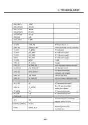
... SIM CARD CC_IO SIM_IO SIM CARD I/O CC_CLK SIM_CLK CC_RST SIM_RST I2S I2S2_CLK0 Not Use GPIO_102 _WP I2S2_RX Not Use I2S2_TX Not Use I2S2_WA0 Not Use I2S2_WA1 Not Use EXTERNAL MEMORY MMCI_CMD TF_CMD MMCI_DAT[0] TF_DAT0 MMCI_CLK TF_CLK BT I /O SIM CARD CLOCK SIM CARD RESET Not Connected For T-Flash " " For Bluetooth " USB End of charging detect(High: EOC, Low: charging) Remote power on detect (High: Remote , Low: Normal Audio pass select( high: Speaker, Low: Receiver) For Bluetooth For Camera Flash...
... SIM CARD CC_IO SIM_IO SIM CARD I/O CC_CLK SIM_CLK CC_RST SIM_RST I2S I2S2_CLK0 Not Use GPIO_102 _WP I2S2_RX Not Use I2S2_TX Not Use I2S2_WA0 Not Use I2S2_WA1 Not Use EXTERNAL MEMORY MMCI_CMD TF_CMD MMCI_DAT[0] TF_DAT0 MMCI_CLK TF_CLK BT I /O SIM CARD CLOCK SIM CARD RESET Not Connected For T-Flash " " For Bluetooth " USB End of charging detect(High: EOC, Low: charging) Remote power on detect (High: Remote , Low: Normal Audio pass select( high: Speaker, Low: Receiver) For Bluetooth For Camera Flash...
Service Manual
Page 30
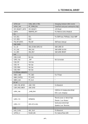
3. TECHNICAL BRIEF EBU_WAIT_n EBU_SDCLKO EBU_SDCLKI EBU_BFCLKO EBU_BFCLKI EBU_CKE SSC1_SCLK _WAIT SDCLKO SDCLKI BFCLKO BFCLKI CKE F_DPD T_OUT0 GPIO_44 T_OUT2 T_OUT3 T_OUT4 EINT3 T_OUT6 GPIO_50 GPIO_51 CC1CC3IO GPIO_53 GPIO_54 GPIO_55 TXON_PA VIBRATOR_EN PA_BAND ANT_SW1 ANT_SW2 ANT_SW3 MODE KP_OUT(4) AU_PWR_EN LCD BACKLIGHT JACK_DETECT _FM_RESET AF_PWR_EN RF_STR0 GPIO_57 RF_DATA RF_CLK System port AFC CLKOUT0 [
3. TECHNICAL BRIEF EBU_WAIT_n EBU_SDCLKO EBU_SDCLKI EBU_BFCLKO EBU_BFCLKI EBU_CKE SSC1_SCLK _WAIT SDCLKO SDCLKI BFCLKO BFCLKI CKE F_DPD T_OUT0 GPIO_44 T_OUT2 T_OUT3 T_OUT4 EINT3 T_OUT6 GPIO_50 GPIO_51 CC1CC3IO GPIO_53 GPIO_54 GPIO_55 TXON_PA VIBRATOR_EN PA_BAND ANT_SW1 ANT_SW2 ANT_SW3 MODE KP_OUT(4) AU_PWR_EN LCD BACKLIGHT JACK_DETECT _FM_RESET AF_PWR_EN RF_STR0 GPIO_57 RF_DATA RF_CLK System port AFC CLKOUT0 [
Service Manual
Page 32
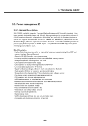
... independent switching of two SIM cards • LDO regulators for baseband I/O supply • LDO regulator for analog mixed-signal section of S-GOLD • Low-noise LDO regulators for RF devices • Supply for Bluemoon Single, Infineon's single chip solution for Bluetooth • Audio amplifier 8 Ohms for handsfree operation and ringing • Charge Control for charging Li-Ion/Polymer batteries under software...
... independent switching of two SIM cards • LDO regulators for baseband I/O supply • LDO regulator for analog mixed-signal section of S-GOLD • Low-noise LDO regulators for RF devices • Supply for Bluemoon Single, Infineon's single chip solution for Bluetooth • Audio amplifier 8 Ohms for handsfree operation and ringing • Charge Control for charging Li-Ion/Polymer batteries under software...
Service Manual
Page 34
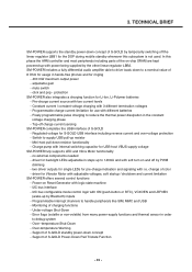
... Bluetooth) inputs - two driver outputs for single LEDs for use with i.e. Support of color - In this subsystem is not used. click and pop - Switch to handle peripherals like SIM, MMC and USB - change of S-GOLD standby power-down resistor functionality - 3. Programmable charge current limitation for pre-charge indication and signaling with different batteries - Top-off the linear regulator LBB1 for ringing - 400 mW maximum output power...
... Bluetooth) inputs - two driver outputs for single LEDs for use with i.e. Support of color - In this subsystem is not used. click and pop - Switch to handle peripherals like SIM, MMC and USB - change of S-GOLD standby power-down resistor functionality - 3. Programmable charge current limitation for pre-charge indication and signaling with different batteries - Top-off the linear regulator LBB1 for ringing - 400 mW maximum output power...

Service Manual
Page 38
... ] Power-ON-charging : Charger detect. ] Power-ON-remote : remote power on detect (Factory use only) Figure 8 Power on function for SM-POWER with 2 active high levels (see Figure 8). It might be set. As monitoring the RPWRON(GPIO_110) and Key matrix KP_OUT(1) & KP_IN(5), KE600/KE608 system recognize whether remote power on input for factory mass production, applied an analog switch as well. To detect if the push-button...
... ] Power-ON-charging : Charger detect. ] Power-ON-remote : remote power on detect (Factory use only) Figure 8 Power on function for SM-POWER with 2 active high levels (see Figure 8). It might be set. As monitoring the RPWRON(GPIO_110) and Key matrix KP_OUT(1) & KP_IN(5), KE600/KE608 system recognize whether remote power on input for factory mass production, applied an analog switch as well. To detect if the push-button...
Service Manual
Page 43
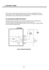
... configuration of the SM-POWER LED drivers is shown in the KE600.KE608) Figure 14 Keypad Back-light LEDs - 44 - TECHNICAL BRIEF Numeric keys, Camera key and volume up & down keys are located on the SUB PCB, are not used in below Figure14. (SLED1, SLED2 port are connected via 50pin board to board connector between main PCB and FPCB. 3.9. Keypad back-light illumination There...
... configuration of the SM-POWER LED drivers is shown in the KE600.KE608) Figure 14 Keypad Back-light LEDs - 44 - TECHNICAL BRIEF Numeric keys, Camera key and volume up & down keys are located on the SUB PCB, are not used in below Figure14. (SLED1, SLED2 port are connected via 50pin board to board connector between main PCB and FPCB. 3.9. Keypad back-light illumination There...
Service Manual
Page 59
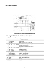
... with power control 3.18. 12pin Multi Media Interface connector Table 11 Multi media interface pin assign KE600/KE608 MMI Pin Function Description 1 FM_ANT FM radio antenna / Audio ground Headset microphone positive signal / 2 HS_MIC_P / HS_ VMICP HS_ Mic positive source Headset microphone negative signal / 3 HS_MIC_N / HS_ VMICN HS_ Mic negative source 4 HS_OUT_L Headset left sound 5 HS_OUT_R Headset Right sound 6 HS_DETECT Headset detect (active...
... with power control 3.18. 12pin Multi Media Interface connector Table 11 Multi media interface pin assign KE600/KE608 MMI Pin Function Description 1 FM_ANT FM radio antenna / Audio ground Headset microphone positive signal / 2 HS_MIC_P / HS_ VMICP HS_ Mic positive source Headset microphone negative signal / 3 HS_MIC_N / HS_ VMICN HS_ Mic negative source 4 HS_OUT_L Headset left sound 5 HS_OUT_R Headset Right sound 6 HS_DETECT Headset detect (active...

Service Manual
Page 75
5. Follow trouble shooting procedure 5.2 Power on all of LDOs from PMIC - 76 - Connect mobile switch cable between Communication test set and DUT when you need to the DUT for power up. - Trouble shooting 5. Trouble shooting 5.1 Trouble shooting test setup 4.000V 0.0000A Figure 51 Equipment setup Power on Trouble Check Points -Battery Voltage( Need to over 3.35V) -Power-On Key detection (PWRON signal) -Outputs of test equipment - Connect PIF-UNION JIG or dummy battery to make a phone call. -
5. Follow trouble shooting procedure 5.2 Power on all of LDOs from PMIC - 76 - Connect mobile switch cable between Communication test set and DUT when you need to the DUT for power up. - Trouble shooting 5. Trouble shooting 5.1 Trouble shooting test setup 4.000V 0.0000A Figure 51 Equipment setup Power on Trouble Check Points -Battery Voltage( Need to over 3.35V) -Power-On Key detection (PWRON signal) -Outputs of test equipment - Connect PIF-UNION JIG or dummy battery to make a phone call. -

Service Manual
Page 91
Trouble shooting START Check Vibrator contact Pin1 of U401 is high ? Yes Pin3 of U401 is low? Yes Replace Vibrator No Check U401 or replace it No Check U401 or replace it Assemble - 92 - 5.
Trouble shooting START Check Vibrator contact Pin1 of U401 is high ? Yes Pin3 of U401 is low? Yes Replace Vibrator No Check U401 or replace it No Check U401 or replace it Assemble - 92 - 5.

Service Manual
Page 95
No Repair it No Replace the damaged part Assemble - 96 - Yes Q301 is working? 5. Trouble shooting START Check All of SIM card voltage KE600/KE608 support 1.8V & 3V SIM only 6 pins are soldered well?
No Repair it No Replace the damaged part Assemble - 96 - Yes Q301 is working? 5. Trouble shooting START Check All of SIM card voltage KE600/KE608 support 1.8V & 3V SIM only 6 pins are soldered well?

Service Manual
Page 97
5. Yes Q1 is working properly? Trouble shooting TFlash_DETECT Q1_Point START Check the Card detect signal if it No Replace the damaged part - 98 - Assemble No Repair it operate as above picture TF_DETECT pins are soldered well?
5. Yes Q1 is working properly? Trouble shooting TFlash_DETECT Q1_Point START Check the Card detect signal if it No Replace the damaged part - 98 - Assemble No Repair it operate as above picture TF_DETECT pins are soldered well?
Service Manual
Page 142
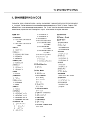
... test menu. [1] BB TEST [1-1]Back Light [1-1-1] LCD Back Light Always On Enable [1-1-2] LCD Back Light Always On Disable [1-2]LCD [1-2-1] LCD Color [1-3]Camera [1-3-1] Camera Main Preview [1-3-2] Flash On [1-3-3] Flash Off [1-4]Battery Info [1-4-1] Battery Info [1-5]Vibrator [1-5-1] Vibrator On [1-5-2] Vibrator Off [1-6]DAI [1-6-1] Close [1-7]SD CARD [1-7-1] Close [1-8]Connection [1-8-1] Bluetooth [1-8-2] Irda [1-9]Audio [1-9-1] Close [1-0]FM Radio [1-0-1] FM Radio Turn On [1-0-2] FM Radio Turn Off [1-0-3] FM Radio Seek Up [1-0-4] FM Radio Seek Down [1-*]Bluetooth Test [1-*-1] Enter Test Mode...
... test menu. [1] BB TEST [1-1]Back Light [1-1-1] LCD Back Light Always On Enable [1-1-2] LCD Back Light Always On Disable [1-2]LCD [1-2-1] LCD Color [1-3]Camera [1-3-1] Camera Main Preview [1-3-2] Flash On [1-3-3] Flash Off [1-4]Battery Info [1-4-1] Battery Info [1-5]Vibrator [1-5-1] Vibrator On [1-5-2] Vibrator Off [1-6]DAI [1-6-1] Close [1-7]SD CARD [1-7-1] Close [1-8]Connection [1-8-1] Bluetooth [1-8-2] Irda [1-9]Audio [1-9-1] Close [1-0]FM Radio [1-0-1] FM Radio Turn On [1-0-2] FM Radio Turn Off [1-0-3] FM Radio Seek Up [1-0-4] FM Radio Seek Down [1-*]Bluetooth Test [1-*-1] Enter Test Mode...


