Service Manual
Page 4
.... EXPLODED VIEW & REPLACEMENT PART LIST ..... 145 12.1 Exploded View 145 12.2 Replacement Parts 147 12.3 Accessory 167 -5- TECHNICAL BRIEF 19 3.1 KE600 / KE608 Component Block diagram 19 3.2 Baseband Processor (BBP) Introduction 21 3.3 Power management IC 33 3.4 Power ON/OFF 39 3.5 SIM interface 40... 41 3.7 LCD Display 42 3.8 Keypad Switching & Scanning 43 3.9 Keypad back-light illumination 44 3.10 LCD back light illumination 46 3.11 Battery current consumption monitor ...48 3.12 JTAG & ETM interface connector ........48 3.13 Audio 49 3.14 USB charging circuit 52 3.15 FM radio...
.... EXPLODED VIEW & REPLACEMENT PART LIST ..... 145 12.1 Exploded View 145 12.2 Replacement Parts 147 12.3 Accessory 167 -5- TECHNICAL BRIEF 19 3.1 KE600 / KE608 Component Block diagram 19 3.2 Baseband Processor (BBP) Introduction 21 3.3 Power management IC 33 3.4 Power ON/OFF 39 3.5 SIM interface 40... 41 3.7 LCD Display 42 3.8 Keypad Switching & Scanning 43 3.9 Keypad back-light illumination 44 3.10 LCD back light illumination 46 3.11 Battery current consumption monitor ...48 3.12 JTAG & ETM interface connector ........48 3.13 Audio 49 3.14 USB charging circuit 52 3.15 FM radio...
Service Manual
Page 10
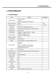
PERFORMANCE 2.1 H/W Feature Item Standard Battery AVG TCVR Current Standby Current Talk time Standby time Charging time RX Sensitivity TX output power GPRS compatibility SIM card type Display Status Indicator ANT EAR Phone Jack PC Synchronization Speech coding Data and Fax Vibrator Buzzer Voice Recoding C-Mic Receiver Travel Adapter Options Feature Li-Poly, 950mAh Battery Size :36.50(W)x58.50(H)x3.65(T)[mm] 280mA 2. PERFORMANCE 2.
PERFORMANCE 2.1 H/W Feature Item Standard Battery AVG TCVR Current Standby Current Talk time Standby time Charging time RX Sensitivity TX output power GPRS compatibility SIM card type Display Status Indicator ANT EAR Phone Jack PC Synchronization Speech coding Data and Fax Vibrator Buzzer Voice Recoding C-Mic Receiver Travel Adapter Options Feature Li-Poly, 950mAh Battery Size :36.50(W)x58.50(H)x3.65(T)[mm] 280mA 2. PERFORMANCE 2.
Service Manual
Page 14
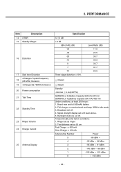
Full charge, no receive/send and keep GSM in idle mode. 3. Backlight of phone set off . 4. At least 65 dB under below conditions: 1. Broadcast set as 50 cm Fast Charge : < 600 mA Slow Charge: < 120 mA Antenna Bar Number ... dBm 0 ~ -105 dBm - 15 - Ringer set off . Test distance set at least 200 hours: 1. 2. Brand new and full 950mAh battery 2. Normal 3 mA(@PP9) GSM900/Lvl 5 (Battery Capacity 950mA):240 min GSM900/Lvl 12(Battery Capacity 950 mA):420 min Under conditions, at 3 level above. 5. Signal strength display set as ringer. 2. PERFORMANCE Item Description...
Full charge, no receive/send and keep GSM in idle mode. 3. Backlight of phone set off . 4. At least 65 dB under below conditions: 1. Broadcast set as 50 cm Fast Charge : < 600 mA Slow Charge: < 120 mA Antenna Bar Number ... dBm 0 ~ -105 dBm - 15 - Ringer set off . Test distance set at least 200 hours: 1. 2. Brand new and full 950mAh battery 2. Normal 3 mA(@PP9) GSM900/Lvl 5 (Battery Capacity 950mA):240 min GSM900/Lvl 12(Battery Capacity 950 mA):420 min Under conditions, at 3 level above. 5. Signal strength display set as ringer. 2. PERFORMANCE Item Description...

Service Manual
Page 15
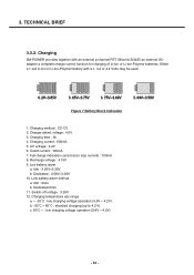
PERFORMANCE Item Description 26 Battery Indicator 27 Low Voltage Warning 28 Forced shut down Voltage 29 Battery Type 30 Travel Charger Specification Battery Bar Number Voltage( 0.05V) 4 3.86V~4.2V 3 3.75V~3.85V 2 3.75V~3.69V 1 3.69V~3.58V 0 3.58V~ 3.58V↓ 0.05V (Call) 3.50V↓ 0.05V (Standby) 3.35 0.05 V Li-ion Battery Standard Voltage = 3.7 V Battery full charge voltage = 4.2 V Capacity: 950mAh Switching-mode charger Input: 100 ~ 240 V, 50/60Hz Out put: 5.2, 0.8A - 16 - 2.
PERFORMANCE Item Description 26 Battery Indicator 27 Low Voltage Warning 28 Forced shut down Voltage 29 Battery Type 30 Travel Charger Specification Battery Bar Number Voltage( 0.05V) 4 3.86V~4.2V 3 3.75V~3.85V 2 3.75V~3.69V 1 3.69V~3.58V 0 3.58V~ 3.58V↓ 0.05V (Call) 3.50V↓ 0.05V (Standby) 3.35 0.05 V Li-ion Battery Standard Voltage = 3.7 V Battery full charge voltage = 4.2 V Capacity: 950mAh Switching-mode charger Input: 100 ~ 240 V, 50/60Hz Out put: 5.2, 0.8A - 16 - 2.
Service Manual
Page 23
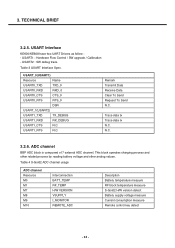
... Send N.C. This block operates charging process and other related process by reading battery voltage and other analog values. USART1 : Hardware Flow Control / SW upgrade / Calibration - USART Interface KE600/KE608 have two UART Drivers as follow : - USART2 : SW debug...channel Resource M0 M1 M7 M8 M9 M10 Interconnection BATT_TEMP RF_TEMP H/W VERSION VSUPPLY I_MONITOR REMOTE_ADC Description Battery temperature measure RF block temperature measure S-Gold2 H/W version detect Battery supply voltage measure Current consumption measure Remote control key detect - 24 - Trace data tx Trace...
... Send N.C. This block operates charging process and other related process by reading battery voltage and other analog values. USART1 : Hardware Flow Control / SW upgrade / Calibration - USART Interface KE600/KE608 have two UART Drivers as follow : - USART2 : SW debug...channel Resource M0 M1 M7 M8 M9 M10 Interconnection BATT_TEMP RF_TEMP H/W VERSION VSUPPLY I_MONITOR REMOTE_ADC Description Battery temperature measure RF block temperature measure S-Gold2 H/W version detect Battery supply voltage measure Current consumption measure Remote control key detect - 24 - Trace data tx Trace...

Service Manual
Page 27
For Bluetooth " " For T-Flash " " For Receiver " For Speaker For Speaker For Mic " For Headset Mic " For Mic " Battery temperature detect RF Power amp reference temperature detect For 18Pin Cable Type Detect HW revision indication Battery voltage measurement Current consumption measurement For Remote Control Headset Key detect with REMOTE_INT For JTAG & ETM Interface " " " " " TECHNICAL...
For Bluetooth " " For T-Flash " " For Receiver " For Speaker For Speaker For Mic " For Headset Mic " For Mic " Battery temperature detect RF Power amp reference temperature detect For 18Pin Cable Type Detect HW revision indication Battery voltage measurement Current consumption measurement For Remote Control Headset Key detect with REMOTE_INT For JTAG & ETM Interface " " " " " TECHNICAL...
Service Manual
Page 32
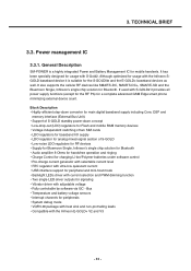
... SGOLD baseband device it provides all power supply functions (except for the RF PA) for a complete advanced GSM Edge smart phone minimizing external device count. Block Description • Highly efficient step-down converter for main digital baseband supply including Core, DSP and... chip solution for Bluetooth • Audio amplifier 8 Ohms for handsfree operation and ringing • Charge Control for charging Li-Ion/Polymer batteries under software control • Pre-charge current generator with selectable current level • RTC regulator with ultra-low quiescent current •...
... SGOLD baseband device it provides all power supply functions (except for the RF PA) for a complete advanced GSM Edge smart phone minimizing external device count. Block Description • Highly efficient step-down converter for main digital baseband supply including Core, DSP and... chip solution for Bluetooth • Audio amplifier 8 Ohms for handsfree operation and ringing • Charge Control for charging Li-Ion/Polymer batteries under software control • Pre-charge current generator with selectable current level • RTC regulator with ultra-low quiescent current •...
Service Manual
Page 33
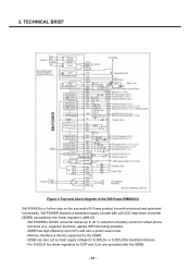
TECHNICAL BRIEF Figure 4 Top level block diagram of battery current for smart phone functions (e.g. SDBB has high efficiency up to 95% and also a power save mode. - SDBB can also act as main supply voltage for DSP and Core ...
TECHNICAL BRIEF Figure 4 Top level block diagram of battery current for smart phone functions (e.g. SDBB has high efficiency up to 95% and also a power save mode. - SDBB can also act as main supply voltage for DSP and Core ...
Service Manual
Page 34
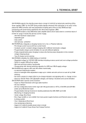
... non-volatile) from many power-supply functions and thermal sensor in order to reduce the thermal power dissipation in hands-free phones and for the DSP during mobile standby whenever this phase the ARM controller and most peripherals including parts of S-GOLD by temporarily... switching off by Bluetooth) inputs - Over-temperature Warning - Support of S-GOLD standby power-down to 140mA and with different batteries - TECHNICAL BRIEF SM-POWER supports the standby power-down resistor functionality - In this subsystem is not used. protection SM-POWER also integrates...
... non-volatile) from many power-supply functions and thermal sensor in order to reduce the thermal power dissipation in hands-free phones and for the DSP during mobile standby whenever this phase the ARM controller and most peripherals including parts of S-GOLD by temporarily... switching off by Bluetooth) inputs - Over-temperature Warning - Support of S-GOLD standby power-down to 140mA and with different batteries - TECHNICAL BRIEF SM-POWER supports the standby power-down resistor functionality - In this subsystem is not used. protection SM-POWER also integrates...

Service Manual
Page 35
... Memory & for LDO RF transceiver DSP in BBP ARM core in BBP Peripherals SIM card Peripherals SD card Analog block in BBP RTC block & Backup battery RF IC RF IC BT IC(Blue moon USB I/F Figure 5 Power domain block diagram of...
... Memory & for LDO RF transceiver DSP in BBP ARM core in BBP Peripherals SIM card Peripherals SD card Analog block in BBP RTC block & Backup battery RF IC RF IC BT IC(Blue moon USB I/F Figure 5 Power domain block diagram of...
Service Manual
Page 37
... operation (3.6V ~ 4.2V) . TECHNICAL BRIEF 3.3.2. Cutoff current : 100mA 7. Dedicated : 3.58V~3.35V 10. Low battery alarm interval a. Charger detect voltage : 4.0V 3. Charging current : 600mA 5. Idle : 2min b. Switch-off voltage : 3.35V 12. 3. Either a 1-cell Li-Ion or Li-Ion-Polymer battery with an external p-channel FET Siliconix Si3455 an external ACadapter a complete charge control function...
... operation (3.6V ~ 4.2V) . TECHNICAL BRIEF 3.3.2. Cutoff current : 100mA 7. Dedicated : 3.58V~3.35V 10. Low battery alarm interval a. Charger detect voltage : 4.0V 3. Charging current : 600mA 5. Idle : 2min b. Switch-off voltage : 3.35V 12. 3. Either a 1-cell Li-Ion or Li-Ion-Polymer battery with an external p-channel FET Siliconix Si3455 an external ACadapter a complete charge control function...
Service Manual
Page 45
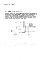
... LEDs. 3. TECHNICAL BRIEF 3.10. The backlight charge pump is capable of driving up to three LEDs at a total of each LED with lithium-ion/polymer batteries. To maximize power efficiency, the charge pump operates in 1X, 1.5X, or 2X mode, where the mode of operation is a dual charge pump designed to...
... LEDs. 3. TECHNICAL BRIEF 3.10. The backlight charge pump is capable of driving up to three LEDs at a total of each LED with lithium-ion/polymer batteries. To maximize power efficiency, the charge pump operates in 1X, 1.5X, or 2X mode, where the mode of operation is a dual charge pump designed to...

Service Manual
Page 47
TECHNICAL BRIEF 3.11 Battery current consumption monitor KE600/KE608 use a current monitoring function to calculate the battery capacity and the remaining time, as monitoring current flow from the battery thru 47mohm resistor. VSUPPLY CN404 1 5 2 4 3 VBAT C408 C409 C410 1u 56p 18p C418 C419 10p 3p R465 47mohm... TRACEPKT3 TRACEPKT2 TRACEPKT1 TRACEPKT0 PIPESTAT2 PIPESTAT1 PIPESTAT0 TRACESYNC Figure 21 JTAG & ETM(Embedded Trace Module) interface connector In case of KE600/KE608 mass production, the JTAG & ETM interface connector will not be mount on mass production PCB) - 48 - 3....
TECHNICAL BRIEF 3.11 Battery current consumption monitor KE600/KE608 use a current monitoring function to calculate the battery capacity and the remaining time, as monitoring current flow from the battery thru 47mohm resistor. VSUPPLY CN404 1 5 2 4 3 VBAT C408 C409 C410 1u 56p 18p C418 C419 10p 3p R465 47mohm... TRACEPKT3 TRACEPKT2 TRACEPKT1 TRACEPKT0 PIPESTAT2 PIPESTAT1 PIPESTAT0 TRACESYNC Figure 21 JTAG & ETM(Embedded Trace Module) interface connector In case of KE600/KE608 mass production, the JTAG & ETM interface connector will not be mount on mass production PCB) - 48 - 3....
Service Manual
Page 51
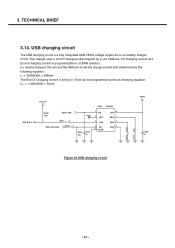
CC charging current and End of charging current is a fully integrated USB VBUS voltage single-cell Li-ion battery charger circuit. The charger uses a CC/CV charge profile required by the as following equation: IEOC = 11000/220K = 50mA USB_EOCn 2V72_IO R250 10K VBUS_USB R221 0 ... determined by the following equation: ICC = 12089/33K = 366mA The End Of Charging current is set by IMIN That can be programmed by Li-ion batteries.
CC charging current and End of charging current is a fully integrated USB VBUS voltage single-cell Li-ion battery charger circuit. The charger uses a CC/CV charge profile required by the as following equation: IEOC = 11000/220K = 50mA USB_EOCn 2V72_IO R250 10K VBUS_USB R221 0 ... determined by the following equation: ICC = 12089/33K = 366mA The End Of Charging current is set by IMIN That can be programmed by Li-ion batteries.

Service Manual
Page 73
4. PCB layout Key light LED LCD connector Back_up battery FPCB connector Jog wheel connector - 74 -
4. PCB layout Key light LED LCD connector Back_up battery FPCB connector Jog wheel connector - 74 -

Service Manual
Page 75
5. Connect mobile switch cable between Communication test set and DUT when you need to the DUT for power up. - Trouble shooting 5. Follow trouble shooting procedure 5.2 Power on all of LDOs from PMIC - 76 - Trouble shooting 5.1 Trouble shooting test setup 4.000V 0.0000A Figure 51 Equipment setup Power on Trouble Check Points -Battery Voltage( Need to over 3.35V) -Power-On Key detection (PWRON signal) -Outputs of test equipment - Connect PIF-UNION JIG or dummy battery to make a phone call. -
5. Connect mobile switch cable between Communication test set and DUT when you need to the DUT for power up. - Trouble shooting 5. Follow trouble shooting procedure 5.2 Power on all of LDOs from PMIC - 76 - Trouble shooting 5.1 Trouble shooting test setup 4.000V 0.0000A Figure 51 Equipment setup Power on Trouble Check Points -Battery Voltage( Need to over 3.35V) -Power-On Key detection (PWRON signal) -Outputs of test equipment - Connect PIF-UNION JIG or dummy battery to make a phone call. -

Service Manual
Page 79
... small charging operation. Trouble shooting 5.3 Charging trouble Check Points -Connection of TA (check TA voltage 4.8V) -Charging Current Path component voltage drop -Battery voltage • Charging method : CC-CV • Charger detect voltage : about 4.0V • ChCharging time : 3h under • Charging current... : 600mA • Cutoff current : 100mA • Low battery alarm - VCHG R209 C227 100K 10u Q201 6 S2 4 S1 1 D3 2 D2 5 D1 3 G NDC652P D201 CRS08 C228 47n VCH_CTL R212 0.15 ...
... small charging operation. Trouble shooting 5.3 Charging trouble Check Points -Connection of TA (check TA voltage 4.8V) -Charging Current Path component voltage drop -Battery voltage • Charging method : CC-CV • Charger detect voltage : about 4.0V • ChCharging time : 3h under • Charging current... : 600mA • Cutoff current : 100mA • Low battery alarm - VCHG R209 C227 100K 10u Q201 6 S2 4 S1 1 D3 2 D2 5 D1 3 G NDC652P D201 CRS08 C228 47n VCH_CTL R212 0.15 ...

Service Manual
Page 80
Yes Battery thermistor Yes Charge is over 3.4V? Trouble shooting START 24pin MMI(CN403) Yes Source pin of Q201= Yes Drain pin of Q201 = Yes D201 voltage drop Yes Battery voltage is operating No Resolder the CN403 No The TA can be broken Change other TA No Check solder Q201 or replace it No Replace it Waiting until No battery Voltage goes up to 3.4V No Change the Battery retest - 81 - 5.
Yes Battery thermistor Yes Charge is over 3.4V? Trouble shooting START 24pin MMI(CN403) Yes Source pin of Q201= Yes Drain pin of Q201 = Yes D201 voltage drop Yes Battery voltage is operating No Resolder the CN403 No The TA can be broken Change other TA No Check solder Q201 or replace it No Replace it Waiting until No battery Voltage goes up to 3.4V No Change the Battery retest - 81 - 5.

Service Manual
Page 115
Download & S/W upgrade 6.1 S/W download setup 4.000V 0.0000A Figure S/W download & upgrade setup Preparation • Target terminal • PIF-Union • RS-232 Cable and PIF-UNION to use battery, the voltage of the battery should be over 3.7V for stable power supplying during S/W download. - 116 - If you are going to Phone interface Cable • Power Supply or Battery • IBM compatible PC supporting RS-232 with Windows 98 or newer. Download & S/W upgrade 6. 6.
Download & S/W upgrade 6.1 S/W download setup 4.000V 0.0000A Figure S/W download & upgrade setup Preparation • Target terminal • PIF-Union • RS-232 Cable and PIF-UNION to use battery, the voltage of the battery should be over 3.7V for stable power supplying during S/W download. - 116 - If you are going to Phone interface Cable • Power Supply or Battery • IBM compatible PC supporting RS-232 with Windows 98 or newer. Download & S/W upgrade 6. 6.
Service Manual
Page 123
... 56p 18p C416 C417 18p 3p VA405 EVL5M02200 H 1 2 2 3 4 5 5 E SLIDE 2V72_IO R444 100K SLIDE_DETECT OUT U402 VDD C406 0.1u F VA404 EVL5M02200 EM-6681-T3 GND VSUPPLY Battery Connector G CN404 1 5 2 4 3 R462 1K BATT_TEMP VBAT C408 C409 C410 1u 56p 18p C418 C419 10p 3p R465 47mohm VIN IOUT 4 3 GND 2 5 LOAD NC 1 ZXCT1010E5TA U403... - 124 - Mobile Handsets R&D Center HW Group, Develpment Lab 4 GSM-NEO-MAIN-1.1 Size: A2 12 1 8 A Changed by : D.H.SEO R&D CHK: DOC CTRL CHK: MFG ENGR CHK: TITLE: H LG ELECTRONICS INC.
... 56p 18p C416 C417 18p 3p VA405 EVL5M02200 H 1 2 2 3 4 5 5 E SLIDE 2V72_IO R444 100K SLIDE_DETECT OUT U402 VDD C406 0.1u F VA404 EVL5M02200 EM-6681-T3 GND VSUPPLY Battery Connector G CN404 1 5 2 4 3 R462 1K BATT_TEMP VBAT C408 C409 C410 1u 56p 18p C418 C419 10p 3p R465 47mohm VIN IOUT 4 3 GND 2 5 LOAD NC 1 ZXCT1010E5TA U403... - 124 - Mobile Handsets R&D Center HW Group, Develpment Lab 4 GSM-NEO-MAIN-1.1 Size: A2 12 1 8 A Changed by : D.H.SEO R&D CHK: DOC CTRL CHK: MFG ENGR CHK: TITLE: H LG ELECTRONICS INC.

