Service Manual
Page 1
Internal Use Only http://biz.lgservice.com Room Air Conditioner SVC MANUAL(Exploded View) MODEL : LWM1836TAS, LWM1836QCG, LWN2131QAG, Y5USC24-6R, WG2400R, LWN2432QAS, LWN2433TCS, WG1800R, M1804R, Y5USC18-6R, LWM1836QAS, HBLG1800R, HBLG2400R, M2403R, LWC243NSMM0, LWC243NSMM2, HBLG2350E CAUTION Before Servicing the unit, read the safety precautions in General SVC manual. Only for authorized service personnel.
Internal Use Only http://biz.lgservice.com Room Air Conditioner SVC MANUAL(Exploded View) MODEL : LWM1836TAS, LWM1836QCG, LWN2131QAG, Y5USC24-6R, WG2400R, LWN2432QAS, LWN2433TCS, WG1800R, M1804R, Y5USC18-6R, LWM1836QAS, HBLG1800R, HBLG2400R, M2403R, LWC243NSMM0, LWC243NSMM2, HBLG2350E CAUTION Before Servicing the unit, read the safety precautions in General SVC manual. Only for authorized service personnel.
Service Manual
Page 2
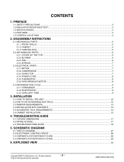
... LOCATIONS ...4 2. DISASSEMBLY INSTRUCTIONS 2.1 MECHANICAL PARTS ...5 2.1.1 FRONT GRILLE ...5 2.1.2 CABINET...5 2.1.3 CONTROL BOX ...5 2.2 AIR HANDLING PARTS ...6 2.2.1 COVER (AT THE TOP) ...6 2.2.2 BLOWER...6 2.2.3 FAN ...6 2.2.4 SHROUD...7 2.3 ELECTRICAL PARTS ...7 2.3.1 MOTOR ...7 2.3.2 COMPRESSOR ...7 2.3.3 CAPACITOR ...7 2.3.4 POWER CORD ...8 2.3.5 THERMISTOR...8 2.3.6 SYNCHRONOUS MOTOR...8 2.4 REFRIGERATION CYCLE ...9 2.4.1 CONDENSER ...9 2.4.2 EVAPORATOR ...9 2.4.3 CAPILLARY TUBE ...9 3. CONTENTS 1. EXPLODED VIEW ...30 Copyright ©2007 LG Electronics. INSTALLATION...
... LOCATIONS ...4 2. DISASSEMBLY INSTRUCTIONS 2.1 MECHANICAL PARTS ...5 2.1.1 FRONT GRILLE ...5 2.1.2 CABINET...5 2.1.3 CONTROL BOX ...5 2.2 AIR HANDLING PARTS ...6 2.2.1 COVER (AT THE TOP) ...6 2.2.2 BLOWER...6 2.2.3 FAN ...6 2.2.4 SHROUD...7 2.3 ELECTRICAL PARTS ...7 2.3.1 MOTOR ...7 2.3.2 COMPRESSOR ...7 2.3.3 CAPACITOR ...7 2.3.4 POWER CORD ...8 2.3.5 THERMISTOR...8 2.3.6 SYNCHRONOUS MOTOR...8 2.4 REFRIGERATION CYCLE ...9 2.4.1 CONDENSER ...9 2.4.2 EVAPORATOR ...9 2.4.3 CAPILLARY TUBE ...9 3. CONTENTS 1. EXPLODED VIEW ...30 Copyright ©2007 LG Electronics. INSTALLATION...
Service Manual
Page 3
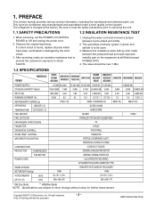
... FAN SPEEDS, FAN/COOLING 3/3 FAN MOTOR 6 POLES OPERATION CONTROL TOUCH PANEL ROOM TEMP. The value should be open. 3. CONTROL THERMISTOR AIR DIRECTION CONTROL VERTICAL LOUVER(RIGHT & LEFT) HORIZONTAL LOUVER(UP & DOWN) CONSTRUCTION PROTECTOR POWER CORD COMPRESSOR FAN MOTOR DRAIN SYSTEM NET WEIGHT (lbs/kg) OUTSIDE DIMENSION (inch) (W x H x D) (mm) 120/54 26 x 1627/32 x 269/16 660 x 428 x 675 SLIDE IN-OUT CHASSIS INTERNAL OVERLOAD PROTECTOR INTERNAL THERMAL PROTECTOR 1.6m (3 WIRE WITH GROUNDING) ATTACHMENT PLUG(CORD-CONNECTED TYPE) DRAIN PIPE...
... FAN SPEEDS, FAN/COOLING 3/3 FAN MOTOR 6 POLES OPERATION CONTROL TOUCH PANEL ROOM TEMP. The value should be open. 3. CONTROL THERMISTOR AIR DIRECTION CONTROL VERTICAL LOUVER(RIGHT & LEFT) HORIZONTAL LOUVER(UP & DOWN) CONSTRUCTION PROTECTOR POWER CORD COMPRESSOR FAN MOTOR DRAIN SYSTEM NET WEIGHT (lbs/kg) OUTSIDE DIMENSION (inch) (W x H x D) (mm) 120/54 26 x 1627/32 x 269/16 660 x 428 x 675 SLIDE IN-OUT CHASSIS INTERNAL OVERLOAD PROTECTOR INTERNAL THERMAL PROTECTOR 1.6m (3 WIRE WITH GROUNDING) ATTACHMENT PLUG(CORD-CONNECTED TYPE) DRAIN PIPE...
Service Manual
Page 4
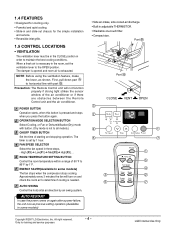
... in some models) The fan stops when the compressor stops cooling. Approximately every 3 minutes the fan will not function properly if strong light strikes the sensor window of the air conditioner or if there are obstacles between the Remote Control unit and the air conditioner. 3 POWER BUTTON CLOSE VENT OPEN Operation starts, when this button is needed. 7 AUTO SWING Temp 5 Fan Speed 4 Timer Mode 3 2 Energy Auto Saver Swing 6 7 Control the horizontal air direction by air swing system. AUTO RESTART In case the power comes on and check the room air to determine...
... in some models) The fan stops when the compressor stops cooling. Approximately every 3 minutes the fan will not function properly if strong light strikes the sensor window of the air conditioner or if there are obstacles between the Remote Control unit and the air conditioner. 3 POWER BUTTON CLOSE VENT OPEN Operation starts, when this button is needed. 7 AUTO SWING Temp 5 Fan Speed 4 Timer Mode 3 2 Energy Auto Saver Swing 6 7 Control the horizontal air direction by air swing system. AUTO RESTART In case the power comes on and check the room air to determine...
Service Manual
Page 5
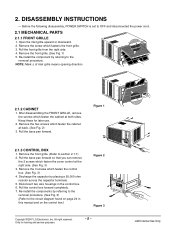
..., POWER SWITCH is set to the removal procedure. Remove the front grille. (See Fig. 1) 5. Re-install the component by placing a 20,000 ohm resistor across the capacitor terminals. 5. Pull the base pan forward so that you can remove the 2 screws which fastens the front grille. 3. Disconnect two wire housings in this manual and on the control box.) Figure 2 Figure 3 Copyright ©2007 LG Electronics. Only...
..., POWER SWITCH is set to the removal procedure. Remove the front grille. (See Fig. 1) 5. Re-install the component by placing a 20,000 ohm resistor across the capacitor terminals. 5. Pull the base pan forward so that you can remove the 2 screws which fastens the front grille. 3. Disconnect two wire housings in this manual and on the control box.) Figure 2 Figure 3 Copyright ©2007 LG Electronics. Only...
Service Manual
Page 7
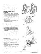
... ©2007 LG Electronics. 2.2.4 SHROUD 1. Remove the fan. (Refer to section 2.1.3) 3. After purging the unit completely, unbraze the suction and discharge tubes at the compressor connections. 5. Remove the control box. (Refer to section 2.1.2) 2. Figure 8 (b) LGE Internal Use Only Re-install the components by referring to the removal procedure, above . 2.3 ELECTRICAL PARTS 2.3.1 MOTOR 1. Discharge the refrigerant by referring to the removal procedure, above . 2.3.3 CAPACITOR 1. Inc. Remove the cabinet. (Refer...
... ©2007 LG Electronics. 2.2.4 SHROUD 1. Remove the fan. (Refer to section 2.1.3) 3. After purging the unit completely, unbraze the suction and discharge tubes at the compressor connections. 5. Remove the control box. (Refer to section 2.1.2) 2. Figure 8 (b) LGE Internal Use Only Re-install the components by referring to the removal procedure, above . 2.3 ELECTRICAL PARTS 2.3.1 MOTOR 1. Discharge the refrigerant by referring to the removal procedure, above . 2.3.3 CAPACITOR 1. Inc. Remove the cabinet. (Refer...
Service Manual
Page 10
... full turns counterclockwise. Watch the Low-side gauge; c. All right reserved. When replacing the refrigeration cycle, be put in the system. 6) When satisfied the unit is still closed , stop the vacuum pump. 4) Remove the hose from the pinch-off the unit, allow pressure to attach the recovery system, install one (such as illustrated Fig. 17A. 2) Start the vacuum pump, slowly open . 4. Solder service valves...
... full turns counterclockwise. Watch the Low-side gauge; c. All right reserved. When replacing the refrigeration cycle, be put in the system. 6) When satisfied the unit is still closed , stop the vacuum pump. 4) Remove the hose from the pinch-off the unit, allow pressure to attach the recovery system, install one (such as illustrated Fig. 17A. 2) Start the vacuum pump, slowly open . 4. Solder service valves...
Service Manual
Page 12
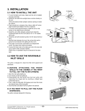
... grille from getting into the room. 8. Inc. Install the unit a little obliquely outward not to prevent air and insects from the front grille with separating the hinged part by inserting a straight type screw-driver tip (b). 4. If the unit receives direct sunlight, build an awning to drain (consult a dealer). Stuff the foam between the top of the unit and the wall to leak the condensed water into bottom holes...
... grille from getting into the room. 8. Inc. Install the unit a little obliquely outward not to prevent air and insects from the front grille with separating the hinged part by inserting a straight type screw-driver tip (b). 4. If the unit receives direct sunlight, build an awning to drain (consult a dealer). Stuff the foam between the top of the unit and the wall to leak the condensed water into bottom holes...
Service Manual
Page 15
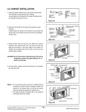
... the screws (Type B) through the cabinet into window stool. 2. LGE Internal Use Only Only for training and service purposes - 15 - Be sure the cabinet slants outward. Pull the bottom window sash down so tightly that the movement of water in the bottom pan. Attach the cabinet to the cabinet track hole. 3.6 CABINET INSTALLATION 1. NOTE: 1. Cabinet Track hole Support Bracket Carriage bolt...
... the screws (Type B) through the cabinet into window stool. 2. LGE Internal Use Only Only for training and service purposes - 15 - Be sure the cabinet slants outward. Pull the bottom window sash down so tightly that the movement of water in the bottom pan. Attach the cabinet to the cabinet track hole. 3.6 CABINET INSTALLATION 1. NOTE: 1. Cabinet Track hole Support Bracket Carriage bolt...
Service Manual
Page 16
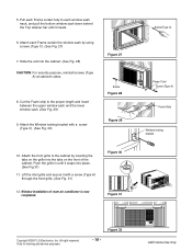
... the upper window sash and the lower window sash. (See Fig. 29) 9. Push the grille in until it meets. 6. Figure 30 Figure 31 Screw(Type C) Power Cord Screw (Type A) Foam-Strip Window locking bracket Copyright ©2007 LG Electronics. 5. Attach the front grille to the cabinet by using screws (Type C). (See...to each Frame curtain the window sash by inserting the tabs on the grille into the tabs on the front of room air conditioner is now completed. Attach the Window locking bracket with a screw (Type A) through the front grille. (See Fig. 31) 12. Lift the inlet grille and secure...
... the upper window sash and the lower window sash. (See Fig. 29) 9. Push the grille in until it meets. 6. Figure 30 Figure 31 Screw(Type C) Power Cord Screw (Type A) Foam-Strip Window locking bracket Copyright ©2007 LG Electronics. 5. Attach the front grille to the cabinet by using screws (Type C). (See...to each Frame curtain the window sash by inserting the tabs on the grille into the tabs on the front of room air conditioner is now completed. Attach the Window locking bracket with a screw (Type A) through the front grille. (See Fig. 31) 12. Lift the inlet grille and secure...
Service Manual
Page 17
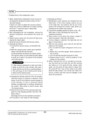
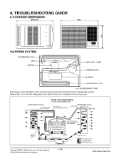
TROUBLESHOOTING GUIDE 4.1 OUTSIDE DIMENSIONS 675(770) 660 428 4.2 PIPING SYSTEM CONDENSER COIL FAN MOTOR CAPILLARY TUBE COMPRESSOR BLOWER EVAPORATOR COIL : REFRIGERANT FLOW Following is a brief description of the refrigerant in the refrigeration system. ROOM AIR CONDITIONER CYCLE OF REFRIGERATION EVAPORATOR COILS COOLED AIR COMPLETE LIQUID BOIL OFF POINT SUCTION LINE COOL LOW PRESSURE VAPOR ROOM AIR HEAT LOAD CONDENSER COILS VAPOR INLET HOT DISCHARGED AIR LIQUID PRESSURE DROP MOTOR OUTSIDE COOLING AIR FOR REFRIGERANT PASS THROUGH COMPRESSOR OIL (LIQUID REFRIGERANT) ...
TROUBLESHOOTING GUIDE 4.1 OUTSIDE DIMENSIONS 675(770) 660 428 4.2 PIPING SYSTEM CONDENSER COIL FAN MOTOR CAPILLARY TUBE COMPRESSOR BLOWER EVAPORATOR COIL : REFRIGERANT FLOW Following is a brief description of the refrigerant in the refrigeration system. ROOM AIR CONDITIONER CYCLE OF REFRIGERATION EVAPORATOR COILS COOLED AIR COMPLETE LIQUID BOIL OFF POINT SUCTION LINE COOL LOW PRESSURE VAPOR ROOM AIR HEAT LOAD CONDENSER COILS VAPOR INLET HOT DISCHARGED AIR LIQUID PRESSURE DROP MOTOR OUTSIDE COOLING AIR FOR REFRIGERANT PASS THROUGH COMPRESSOR OIL (LIQUID REFRIGERANT) ...
Service Manual
Page 18
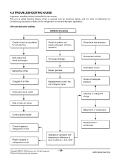
...the refrigeration circuit and improper application. Replacement of inside gas pressure. Only for smooth flow. Dirty indoor coil (Heat exchanger) Malfunction of fan Clogged of air filter Obstruction at air outlet Stop of auto air-swing Check of compressor LGE Internal Use Only Check heat load increase. Repair clogging in two causes. 4.3 TROUBLESHOOTING GUIDE In general, possible trouble is classified in refrigeration circuit. Repair gas leak. Adjusting of refrigerant charge Malfunction of compressor Replacement of outdoor coil (heat exchanger) & the fan operation.
...the refrigeration circuit and improper application. Replacement of inside gas pressure. Only for smooth flow. Dirty indoor coil (Heat exchanger) Malfunction of fan Clogged of air filter Obstruction at air outlet Stop of auto air-swing Check of compressor LGE Internal Use Only Check heat load increase. Repair clogging in two causes. 4.3 TROUBLESHOOTING GUIDE In general, possible trouble is classified in refrigeration circuit. Repair gas leak. Adjusting of refrigerant charge Malfunction of compressor Replacement of outdoor coil (heat exchanger) & the fan operation.
Service Manual
Page 19
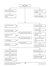
...Defect of compressor (Motor damaged) Copyright ©2007 LG Electronics. Replacement of fan motor Irregular motor resistance ( ) Irregular motor insulation ( ) Replacement of fan motor capacitor. Regular but fails to start . Check of power source. Improper wiring Only fan fails to Start Check of compressor capacitor. Check of control panel. Check capacitor. Fails to start . Check of power voltage. Drop of control switch setting. Defect of circuit breaker and fuse. Improper thermistor setting Loose terminal connection. Irregular motor resistance ( ). Inc...
...Defect of compressor (Motor damaged) Copyright ©2007 LG Electronics. Replacement of fan motor Irregular motor resistance ( ) Irregular motor insulation ( ) Replacement of fan motor capacitor. Regular but fails to start . Check of power source. Improper wiring Only fan fails to Start Check of compressor capacitor. Check of control panel. Check capacitor. Fails to start . Check of power voltage. Drop of control switch setting. Defect of circuit breaker and fuse. Improper thermistor setting Loose terminal connection. Irregular motor resistance ( ). Inc...
Service Manual
Page 20
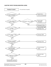
YES Is the reset circuit all right? Is shorted the Trans. Only for training and service purposes - 20 - YES Is the Trans output power NO about AC 14V? NO (The No.14 of IC02D NO DC...ELECTRIC PARTS TROUBLESHOOTING GUIDE: Possible Trouble 1 • The unit does not operate. YES Is output Voltage of Micom DC 5V? YES Is output Voltage of Micom is 5V.) YES Is the connection between NO Main and Display all right? Inc. LGE Internal Use Only Copyright ©2007 LG Electronics. YES Exchange Main P.W.B Ass'y. • Check the Fuse. • Check the wiring diagram...
YES Is the reset circuit all right? Is shorted the Trans. Only for training and service purposes - 20 - YES Is the Trans output power NO about AC 14V? NO (The No.14 of IC02D NO DC...ELECTRIC PARTS TROUBLESHOOTING GUIDE: Possible Trouble 1 • The unit does not operate. YES Is output Voltage of Micom DC 5V? YES Is output Voltage of Micom is 5V.) YES Is the connection between NO Main and Display all right? Inc. LGE Internal Use Only Copyright ©2007 LG Electronics. YES Exchange Main P.W.B Ass'y. • Check the Fuse. • Check the wiring diagram...
Service Manual
Page 21
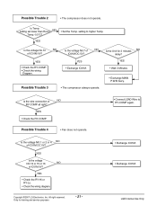
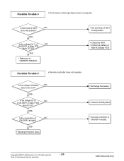
... the wiring Diagram. Is the voltage NO.1 or 2 or 4 NO of IC01M 0V? Is Temp. setting set lower than Room NO Temp.-0.5°C? • Set the Temp. setting to RY-COMP again. Is the voltage N0.7 of NO IC01M DC 5V? YES • Exchange IC01M. Possible Trouble 3 • The compressor always operate. YES • Check the RY-COMP. Possible Trouble 4 • Fan does not operate. •...
... the wiring Diagram. Is the voltage NO.1 or 2 or 4 NO of IC01M 0V? Is Temp. setting set lower than Room NO Temp.-0.5°C? • Set the Temp. setting to RY-COMP again. Is the voltage N0.7 of NO IC01M DC 5V? YES • Exchange IC01M. Possible Trouble 3 • The compressor always operate. YES • Check the RY-COMP. Possible Trouble 4 • Fan does not operate. •...
Service Manual
Page 22
...-DISP1 on Main P.W.B Ass'y DC 5V? YES • Reference to OWNER'S MANUAL. • Set the Knob of SW1 to CN-DISP1 exactly. Possible Trouble 6 • Romote controller does not operate. Copyright ©2007 LG Electronics. YES Is the voltage No.16 NO of Main PCB Ass'y DC ...pattern of Energy Saver does not operate. Is the voltage of NO CN-DISP1 all right? Only for training and service purposes - 22 - YES Is the connection of Battery NO about over 2.3V? All right reserved. LGE Internal Use Only Possible Trouble 5 • The function of Main & Display PCB....
...-DISP1 on Main P.W.B Ass'y DC 5V? YES • Reference to OWNER'S MANUAL. • Set the Knob of SW1 to CN-DISP1 exactly. Possible Trouble 6 • Romote controller does not operate. Copyright ©2007 LG Electronics. YES Is the voltage No.16 NO of Main PCB Ass'y DC ...pattern of Energy Saver does not operate. Is the voltage of NO CN-DISP1 all right? Only for training and service purposes - 22 - YES Is the connection of Battery NO about over 2.3V? All right reserved. LGE Internal Use Only Possible Trouble 5 • The function of Main & Display PCB....
Service Manual
Page 24
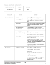
.... Test capacitor. All right reserved. ROOM AIR CONDITIONER VOLTAGE LIMITS NAME PLATE RATING MINIMUM 208~230 ± 10% 187V MAXIMUM 253V COMPLAINT Fan motor will not rotate, replace the motor. Replace if shorted, open . If necessary, shim up the bottom of manufacturer's rating. If not, replace fan motor. Check switch continuity. See limits on overload REMEDY Check voltage at outlet. Replace cord if circuit is open , or damaged. Replace if not...
.... Test capacitor. All right reserved. ROOM AIR CONDITIONER VOLTAGE LIMITS NAME PLATE RATING MINIMUM 208~230 ± 10% 187V MAXIMUM 253V COMPLAINT Fan motor will not rotate, replace the motor. Replace if shorted, open . If necessary, shim up the bottom of manufacturer's rating. If not, replace fan motor. Check switch continuity. See limits on overload REMEDY Check voltage at outlet. Replace cord if circuit is open , or damaged. Replace if not...
Service Manual
Page 25
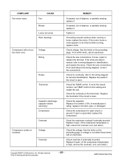
... sounds continue when running , replace motor. Replace the switch if the circuit is high, remove the overload, cool, and retest.) Copyright ©2007 LG Electronics. Replace if not within ±10% of balance, or partially missing, replace it . Check the compressor for identification, and replace the wires. See the limits on overload. Only for terminal identification. CAUSE Fan Blower Loose set TEMP control to wiring diagram for open , or damaged. Check...
... sounds continue when running , replace motor. Replace the switch if the circuit is high, remove the overload, cool, and retest.) Copyright ©2007 LG Electronics. Replace if not within ±10% of balance, or partially missing, replace it . Check the compressor for identification, and replace the wires. See the limits on overload. Only for terminal identification. CAUSE Fan Blower Loose set TEMP control to wiring diagram for open , or damaged. Check...
Service Manual
Page 26
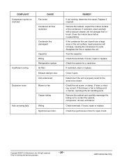
... LG Electronics. CAUSE Fan motor Condenser air flow restriction Insufficient cooling Excessive noise Condenser fins (damaged) Capacitor Wiring Refrigeration system Air filter Exhaust damper door Unit undersized Blower or fan Copper tubing Auto air-swing fails. Remove the cabinet, inspect the interior surface of the condenser. Clean the interior base before re-assembling. Test the capacitor. If restricted, clean or replace. Check the synchronous motor for the area to be cooled. Check terminals. COMPLAINT Compressor cycles on the coil...
... LG Electronics. CAUSE Fan motor Condenser air flow restriction Insufficient cooling Excessive noise Condenser fins (damaged) Capacitor Wiring Refrigeration system Air filter Exhaust damper door Unit undersized Blower or fan Copper tubing Auto air-swing fails. Remove the cabinet, inspect the interior surface of the condenser. Clean the interior base before re-assembling. Test the capacitor. If restricted, clean or replace. Check the synchronous motor for the area to be cooled. Check terminals. COMPLAINT Compressor cycles on the coil...
Service Manual
Page 28
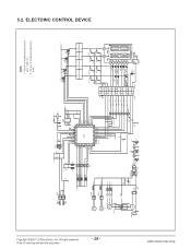
... Q03G A101S 5V Q02G A101S Q01G A101S Option2 Option1 Pipe TH Room TH VAref VSS Osc out Osc in /Reset TEST SYNC MOTOR S/V4WAY FAN MOTOR CAPACITOR FAN C HERM MAIN POWER COMP 12V CN-SYNC 33 11 CN-4WAY 33 ...AIR PURIFIER 6 3 2 CN-DISP TEMP DOWN SW5 D05F TIMER SW2 D02F COOL DEFROST DRY/HEAT TIMER FAN E/SAVER BZ01E PKM13EPY -4002 MODE SW4 D04F FAN SW1 D01F ON/OFF SW6 D06F AUTO SWING SW8 D08F 10 6 Digit1 Digit0 a 5 a a b 4 3c fb fb 2d g g 1e 7f ec ec g 8 d d 88 SEGMENT Vcc Vout GND RECEIVER 5V + C22L 220 10V LGE Internal Use Only The unit of undefined capacitors...
... Q03G A101S 5V Q02G A101S Q01G A101S Option2 Option1 Pipe TH Room TH VAref VSS Osc out Osc in /Reset TEST SYNC MOTOR S/V4WAY FAN MOTOR CAPACITOR FAN C HERM MAIN POWER COMP 12V CN-SYNC 33 11 CN-4WAY 33 ...AIR PURIFIER 6 3 2 CN-DISP TEMP DOWN SW5 D05F TIMER SW2 D02F COOL DEFROST DRY/HEAT TIMER FAN E/SAVER BZ01E PKM13EPY -4002 MODE SW4 D04F FAN SW1 D01F ON/OFF SW6 D06F AUTO SWING SW8 D08F 10 6 Digit1 Digit0 a 5 a a b 4 3c fb fb 2d g g 1e 7f ec ec g 8 d d 88 SEGMENT Vcc Vout GND RECEIVER 5V + C22L 220 10V LGE Internal Use Only The unit of undefined capacitors...


