Service Manual
Page 8
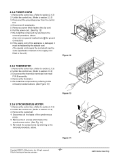
...-install the component by referring to the removal procedure, above. Remove the control box. (Refer to section 2.3.3) 3. Figure 14 Copyright ©2007 LG Electronics. Inc. All right reserved. Disconnect the grounding screw from main P.W.B assembly. 4. Remove a screw which fasten the synchronous motor. (See Fig.... 14) 6. Unfold the control box. (Refer to section 2.1.3) 2. Disconnect all the leads of this appliance is damaged, it must be replaced by referring to the removal procedure above . (Use only one ground-marked hole for training and service...
...-install the component by referring to the removal procedure, above. Remove the control box. (Refer to section 2.3.3) 3. Figure 14 Copyright ©2007 LG Electronics. Inc. All right reserved. Disconnect the grounding screw from main P.W.B assembly. 4. Remove a screw which fasten the synchronous motor. (See Fig.... 14) 6. Unfold the control box. (Refer to section 2.1.3) 2. Disconnect all the leads of this appliance is damaged, it must be replaced by referring to the removal procedure above . (Use only one ground-marked hole for training and service...