Service Manual
Page 2
...FAN ...6 2.2.4 SHROUD...7 2.3 ELECTRICAL PARTS ...7 2.3.1 MOTOR ...7 2.3.2 COMPRESSOR ...7 2.3.3 CAPACITOR ...7 2.3.4 POWER CORD ...8 2.3.5 THERMISTOR...8 2.3.6 SYNCHRONOUS MOTOR...8 2.4 REFRIGERATION CYCLE ...9 2.4.1 CONDENSER ...9 2.4.2 EVAPORATOR ...9 2.4.3 CAPILLARY TUBE ...9 3. TROUBLESHOOTING GUIDE 4.1 OUTSIDE DIMENSIONS...17 4.2 PIPING SYSTEM...17 4.3 TROUBLESHOOTING GUIDE ...18 5. EXPLODED... VIEW ...30 Copyright ©2007 LG Electronics. Only for training and service purposes -2- Inc. CONTENTS 1. INSTALLATION 3.1 HOW TO ...
...FAN ...6 2.2.4 SHROUD...7 2.3 ELECTRICAL PARTS ...7 2.3.1 MOTOR ...7 2.3.2 COMPRESSOR ...7 2.3.3 CAPACITOR ...7 2.3.4 POWER CORD ...8 2.3.5 THERMISTOR...8 2.3.6 SYNCHRONOUS MOTOR...8 2.4 REFRIGERATION CYCLE ...9 2.4.1 CONDENSER ...9 2.4.2 EVAPORATOR ...9 2.4.3 CAPILLARY TUBE ...9 3. TROUBLESHOOTING GUIDE 4.1 OUTSIDE DIMENSIONS...17 4.2 PIPING SYSTEM...17 4.3 TROUBLESHOOTING GUIDE ...18 5. EXPLODED... VIEW ...30 Copyright ©2007 LG Electronics. Only for training and service purposes -2- Inc. CONTENTS 1. INSTALLATION 3.1 HOW TO ...
Service Manual
Page 3
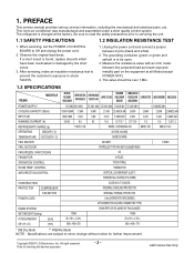
...HBLG1800R LWM1836TASL WN1836QCG LWM1863QAS Y5USC18-6R LWN2131QAG WG2400R HBLG2400R M2403R LWN2432QAS Y5USC24-6R LWC243NSMM0 LWN2433TCS LWC243NSMM2 HBLG2350E POWER SUPPLY 1Ø, 208/230V, 60Hz 1Ø, 220V, 60Hz 1Ø, 220V, ...2,450/2,500 RUNNING CURRENT (A) 9.0/8.3 8.5 8.3 10.3 13.7/12.7 12.7/12.9 11.2 11.5 12.2/11.3 REFRIGERANT CHARGE (g) 710(25.1 OZ) 995(35.1 OZ)/980(34.6 OZ) 880(31 OZ) 985(34.7 OZ... 2. 1. LGE Internal Use Only Inc. Observe the original lead dress. The refrigerant is charged at all parts which have been overheated or damaged by the short circuit...
...HBLG1800R LWM1836TASL WN1836QCG LWM1863QAS Y5USC18-6R LWN2131QAG WG2400R HBLG2400R M2403R LWN2432QAS Y5USC24-6R LWC243NSMM0 LWN2433TCS LWC243NSMM2 HBLG2350E POWER SUPPLY 1Ø, 208/230V, 60Hz 1Ø, 220V, 60Hz 1Ø, 220V, ...2,450/2,500 RUNNING CURRENT (A) 9.0/8.3 8.5 8.3 10.3 13.7/12.7 12.7/12.9 11.2 11.5 12.2/11.3 REFRIGERANT CHARGE (g) 710(25.1 OZ) 995(35.1 OZ)/980(34.6 OZ) 880(31 OZ) 985(34.7 OZ... 2. 1. LGE Internal Use Only Inc. Observe the original lead dress. The refrigerant is charged at all parts which have been overheated or damaged by the short circuit...
Service Manual
Page 7
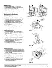
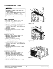
...the shroud. (See Fig. 8) 4. Disconnect the 2 leads from the compressor. 4. Figure 9 Figure 10 Figure 11 Copyright ©2007 LG Electronics. Remove the cabinet. (Refer to section 2.2.2) 4. Remove the blower. (Refer to section 2.1.2) 2. Remove the fan. (Refer to... box. (Refer to section 2.1.3) 2. Figure 8 (a) 2.3.2 COMPRESSOR 1. Discharge the refrigerant by referring to the removal procedure, above . Remove the compressor. 7. Re-install the components by using a Refrigerant Recovery System. 3. Only for training and service purposes -7- Re-install the component by...
...the shroud. (See Fig. 8) 4. Disconnect the 2 leads from the compressor. 4. Figure 9 Figure 10 Figure 11 Copyright ©2007 LG Electronics. Remove the cabinet. (Refer to section 2.2.2) 4. Remove the blower. (Refer to section 2.1.2) 2. Remove the fan. (Refer to... box. (Refer to section 2.1.3) 2. Figure 8 (a) 2.3.2 COMPRESSOR 1. Discharge the refrigerant by referring to the removal procedure, above . Remove the compressor. 7. Re-install the components by using a Refrigerant Recovery System. 3. Only for training and service purposes -7- Re-install the component by...
Service Manual
Page 9
...evaporator sideward carefully and then unbraze the interconnecting tube at the capillary tube. 4. Remove the evaporator. 7. After discharging the refrigerant completely, unbraze the interconnecting tube at the evaporator connectors. 6. Remove the capillary tube. 5. All right reserved. Only ...the condenser. 4. Re-install the components by referring to section 2.1.2) 2. Figure 15 (a) Figure 15 (b) Figure 16 Copyright ©2007 LG Electronics. LGE Internal Use Only Remove the 5 screws which fasten the evaporator at the condenser connections. 5. If there is no valve ...
...evaporator sideward carefully and then unbraze the interconnecting tube at the capillary tube. 4. Remove the evaporator. 7. After discharging the refrigerant completely, unbraze the interconnecting tube at the evaporator connectors. 6. Remove the capillary tube. 5. All right reserved. Only ...the condenser. 4. Re-install the components by referring to section 2.1.2) 2. Figure 15 (a) Figure 15 (b) Figure 16 Copyright ©2007 LG Electronics. LGE Internal Use Only Remove the 5 screws which fasten the evaporator at the condenser connections. 5. If there is no valve ...
Service Manual
Page 10
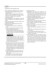
...service purposes - 10 - a. side. allow the proper charge to valve C by means of the charge. d. When replacing the refrigeration cycle, be put in the system. 6) When satisfied the unit is no valve to drop. Leave the valve in the system. ...venting the FreonTM. Close valve A. 5) With the unit running and clamp on the charging cylinder. Do not add the liquid refrigerant to 30 lbs. b. Use sil-fos solder and solder pinch-off tubes with the two full turns counterclockwise. All right ...B and C until 600 microns of the pinch-off tool. Copyright ©2007 LG Electronics.
...service purposes - 10 - a. side. allow the proper charge to valve C by means of the charge. d. When replacing the refrigeration cycle, be put in the system. 6) When satisfied the unit is no valve to drop. Leave the valve in the system. ...venting the FreonTM. Close valve A. 5) With the unit running and clamp on the charging cylinder. Do not add the liquid refrigerant to 30 lbs. b. Use sil-fos solder and solder pinch-off tubes with the two full turns counterclockwise. All right ...B and C until 600 microns of the pinch-off tool. Copyright ©2007 LG Electronics.
Service Manual
Page 17
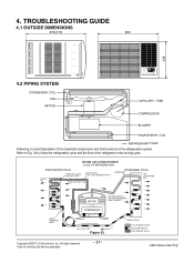
... AIR HEAT LOAD CONDENSER COILS VAPOR INLET HOT DISCHARGED AIR LIQUID PRESSURE DROP MOTOR OUTSIDE COOLING AIR FOR REFRIGERANT PASS THROUGH COMPRESSOR OIL (LIQUID REFRIGERANT) CAPILLARY TUBE Figure 33 LIQUID OUTLET HIGH PRESSURE VAPOR LIQUID PEFRIGERANT LOW PRESSURE VAPOR Copyright ©2007... LG Electronics. Refer to Fig. 33 to follow the refrigeration cycle and the flow of the important components and their functions in the cooling cycle. LGE Internal Use Only TROUBLESHOOTING ...
... AIR HEAT LOAD CONDENSER COILS VAPOR INLET HOT DISCHARGED AIR LIQUID PRESSURE DROP MOTOR OUTSIDE COOLING AIR FOR REFRIGERANT PASS THROUGH COMPRESSOR OIL (LIQUID REFRIGERANT) CAPILLARY TUBE Figure 33 LIQUID OUTLET HIGH PRESSURE VAPOR LIQUID PEFRIGERANT LOW PRESSURE VAPOR Copyright ©2007... LG Electronics. Refer to Fig. 33 to follow the refrigeration cycle and the flow of the important components and their functions in the cooling cycle. LGE Internal Use Only TROUBLESHOOTING ...
Service Manual
Page 18
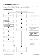
... air filter Obstruction at air outlet Stop of auto air-swing Check of inlet & outlet air ; 44.6~50°F Copyright ©2007 LG Electronics. Satisfactory operation with temperature difference of outdoor coil (heat exchanger) & the fan operation. Check heat load increase. Unexpected residue Overloaded Circuit... classified in two causes. Unit runs but poor cooling Ineffective Cooling Check of compressor LGE Internal Use Only Adjusting of refrigerant charge Malfunction of compressor Replacement of cold air circulation for training and service purposes - 18 - Repair clogging in...
... air filter Obstruction at air outlet Stop of auto air-swing Check of inlet & outlet air ; 44.6~50°F Copyright ©2007 LG Electronics. Satisfactory operation with temperature difference of outdoor coil (heat exchanger) & the fan operation. Check heat load increase. Unexpected residue Overloaded Circuit... classified in two causes. Unit runs but poor cooling Ineffective Cooling Check of compressor LGE Internal Use Only Adjusting of refrigerant charge Malfunction of compressor Replacement of cold air circulation for training and service purposes - 18 - Repair clogging in...
Service Manual
Page 26
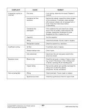
... right reserved. CAUSE Fan motor Condenser air flow restriction Insufficient cooling Excessive noise Condenser fins (damaged) Capacitor Wiring Refrigeration system Air filter Exhaust damper door Unit undersized Blower or fan Copper tubing Auto air-swing fails. Check the system... set screw, or clamp. If loose or missing, correct. Wiring Synchronous motor. Close if open circuit. Copyright ©2007 LG Electronics. COMPLAINT Compressor cycles on the coil surface, head pressures will increase, causing the compressor to cycle. If restricted, clean carefully...
... right reserved. CAUSE Fan motor Condenser air flow restriction Insufficient cooling Excessive noise Condenser fins (damaged) Capacitor Wiring Refrigeration system Air filter Exhaust damper door Unit undersized Blower or fan Copper tubing Auto air-swing fails. Check the system... set screw, or clamp. If loose or missing, correct. Wiring Synchronous motor. Close if open circuit. Copyright ©2007 LG Electronics. COMPLAINT Compressor cycles on the coil surface, head pressures will increase, causing the compressor to cycle. If restricted, clean carefully...
