Service Manual
Page 2
... GRILLE ...5 2.1.2 CABINET...5 2.1.3 CONTROL BOX ...5 2.2 AIR HANDLING PARTS ...6 2.2.1 COVER (AT THE TOP) ...6 2.2.2 BLOWER...6 2.2.3 FAN ...6 2.2.4 SHROUD...7 2.3 ELECTRICAL PARTS ...7 2.3.1 MOTOR ...7 2.3.2 COMPRESSOR ...7 2.3.3 CAPACITOR ...7 2.3.4 POWER CORD ...8 2.3.5 THERMISTOR...8 2.3.6 SYNCHRONOUS MOTOR...8 2.4 REFRIGERATION CYCLE ...9 2.4.1 CONDENSER ...9 2.4.2 EVAPORATOR ...9 2.4.3 CAPILLARY TUBE ...9 3. EXPLODED VIEW ...30 Copyright ©2007 LG Electronics. INSTALLATION 3.1 HOW TO INSTALL THE UNIT...12 3.2 HOW TO USE THE REVERSIBLE INLET GRILLE ...12...
... GRILLE ...5 2.1.2 CABINET...5 2.1.3 CONTROL BOX ...5 2.2 AIR HANDLING PARTS ...6 2.2.1 COVER (AT THE TOP) ...6 2.2.2 BLOWER...6 2.2.3 FAN ...6 2.2.4 SHROUD...7 2.3 ELECTRICAL PARTS ...7 2.3.1 MOTOR ...7 2.3.2 COMPRESSOR ...7 2.3.3 CAPACITOR ...7 2.3.4 POWER CORD ...8 2.3.5 THERMISTOR...8 2.3.6 SYNCHRONOUS MOTOR...8 2.4 REFRIGERATION CYCLE ...9 2.4.1 CONDENSER ...9 2.4.2 EVAPORATOR ...9 2.4.3 CAPILLARY TUBE ...9 3. EXPLODED VIEW ...30 Copyright ©2007 LG Electronics. INSTALLATION 3.1 HOW TO INSTALL THE UNIT...12 3.2 HOW TO USE THE REVERSIBLE INLET GRILLE ...12...
Service Manual
Page 3
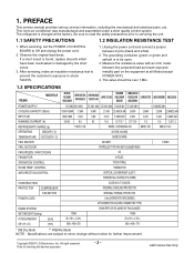
...part on the equipment at the factory. The grounding conductor (green or green and yellow) is to be over 1 MΩ. 1.3 SPECIFICATIONS ITEMS MODELS M1804R WG1800R HBLG1800R LWM1836TASL WN1836QCG LWM1863QAS Y5USC18-6R LWN2131QAG WG2400R HBLG2400R M2403R LWN2432QAS Y5USC24-6R LWC243NSMM0 LWN2433TCS LWC243NSMM2 HBLG2350E...purposes -3- Only for further improvement. If a short circuit is charged at all parts which have been overheated or damaged by the short circuit. 3. Copyright ©2007 LG Electronics. The refrigerant is found, replace all Mode [except POWER OFF]. 4. ...
...part on the equipment at the factory. The grounding conductor (green or green and yellow) is to be over 1 MΩ. 1.3 SPECIFICATIONS ITEMS MODELS M1804R WG1800R HBLG1800R LWM1836TASL WN1836QCG LWM1863QAS Y5USC18-6R LWN2131QAG WG2400R HBLG2400R M2403R LWN2432QAS Y5USC24-6R LWC243NSMM0 LWN2433TCS LWC243NSMM2 HBLG2350E...purposes -3- Only for further improvement. If a short circuit is charged at all parts which have been overheated or damaged by the short circuit. 3. Copyright ©2007 LG Electronics. The refrigerant is found, replace all Mode [except POWER OFF]. 4. ...
Service Manual
Page 4
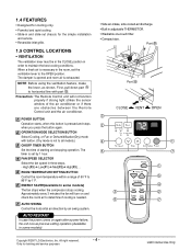
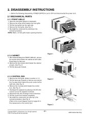
... in adjustable THERMISTOR. • Washable one-touch filter. • Compact size. The 5 7 timer is exhausted. First, pull down part to the OPEN position. Part B 1.5 CONTROL LOCATIONS • VENTILATION The ventilation lever must be in the CLOSE position in three steps. - The damper is opened and... button. (Dry mode is necessary in the room, set by 1°F. 6 ENERGY SAVER(Available In some models) Copyright ©2007 LG Electronics. 1.4 FEATURES • Designed for cooling only. • Powerful and quiet cooling. • Slide-in and slide-out chassis for ...
... in adjustable THERMISTOR. • Washable one-touch filter. • Compact size. The 5 7 timer is exhausted. First, pull down part to the OPEN position. Part B 1.5 CONTROL LOCATIONS • VENTILATION The ventilation lever must be in the CLOSE position in three steps. - The damper is opened and... button. (Dry mode is necessary in the room, set by 1°F. 6 ENERGY SAVER(Available In some models) Copyright ©2007 LG Electronics. 1.4 FEATURES • Designed for cooling only. • Powerful and quiet cooling. • Slide-in and slide-out chassis for ...
Service Manual
Page 5
.... 2. Remove the two screws which fastens the front grille. 3. Discharge the capacitor by referring to OFF and disconnected the power cord. 2.1 MECHANICAL PARTS 2.1.1 FRONT GRILLE 1. All right reserved. Figure 1 2.1.3 CONTROL BOX 1. Re-install the components by referring to the removal procedure. (See Fig.... Fig. 3) 4. Disconnect two wire housings in this manual and on the control box.) Figure 2 Figure 3 Copyright ©2007 LG Electronics. Re-install the component by placing a 20,000 ohm resistor across the capacitor terminals. 5. Pull the base pan forward so...
.... 2. Remove the two screws which fastens the front grille. 3. Discharge the capacitor by referring to OFF and disconnected the power cord. 2.1 MECHANICAL PARTS 2.1.1 FRONT GRILLE 1. All right reserved. Figure 1 2.1.3 CONTROL BOX 1. Re-install the components by referring to the removal procedure. (See Fig.... Fig. 3) 4. Disconnect two wire housings in this manual and on the control box.) Figure 2 Figure 3 Copyright ©2007 LG Electronics. Re-install the component by placing a 20,000 ohm resistor across the capacitor terminals. 5. Pull the base pan forward so...
Service Manual
Page 6
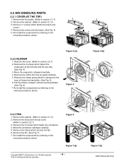
.... Remove the cabinet. (Refer to section 2.2.1) 3. Pull the blower outward, without touching blades. (See Fig. 6) 7. Move the condenser sideways carefully. 5. Figure 6 Figure 7 (a) Copyright ©2007 LG Electronics. Remove the 5 screws which fasten the evaporator at the left side and the top side. (See Fig. 4) 3. Re-install the components by referring to... for training and service purposes -6- Remove the front grille. (Refer to the removal procedure, above . Remove the orifice from the air guide carefully. 5. 2.2 AIR HANDLING PARTS 2.2.1 COVER (AT THE TOP) 1.
.... Remove the cabinet. (Refer to section 2.2.1) 3. Pull the blower outward, without touching blades. (See Fig. 6) 7. Move the condenser sideways carefully. 5. Figure 6 Figure 7 (a) Copyright ©2007 LG Electronics. Remove the 5 screws which fasten the evaporator at the left side and the top side. (See Fig. 4) 3. Re-install the components by referring to... for training and service purposes -6- Remove the front grille. (Refer to the removal procedure, above . Remove the orifice from the air guide carefully. 5. 2.2 AIR HANDLING PARTS 2.2.1 COVER (AT THE TOP) 1.
Service Manual
Page 7
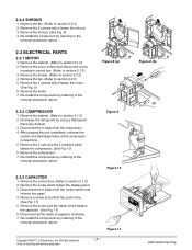
...panel. 3. Remove the screw which fasten the compressor. (See Fig. 10) 6. Figure 9 Figure 10 Figure 11 Copyright ©2007 LG Electronics. Remove the shroud. (See Fig. 8) 4. Re-install the components by referring to the removal procedure, above . 2.3.3 CAPACITOR ...1. Discharge the refrigerant by referring to the removal procedure, above . Re-instill the components by referring to the removal procedure, above . 2.3 ELECTRICAL PARTS 2.3.1 MOTOR 1. Remove a screw and unfold the control box. (See Fig. 11) 5. Figure 8 (b) LGE Internal Use Only 2.2.4 SHROUD 1. Remove ...
...panel. 3. Remove the screw which fasten the compressor. (See Fig. 10) 6. Figure 9 Figure 10 Figure 11 Copyright ©2007 LG Electronics. Remove the shroud. (See Fig. 8) 4. Re-install the components by referring to the removal procedure, above . 2.3.3 CAPACITOR ...1. Discharge the refrigerant by referring to the removal procedure, above . Re-instill the components by referring to the removal procedure, above . 2.3 ELECTRICAL PARTS 2.3.1 MOTOR 1. Remove a screw and unfold the control box. (See Fig. 11) 5. Figure 8 (b) LGE Internal Use Only 2.2.4 SHROUD 1. Remove ...
Service Manual
Page 12
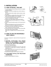
... wall to an independent circuit. If the unit receives direct sunlight, build an awning to drain (consult a dealer). Install the unit with separating the hinged part by inserting a straight type screw-driver tip (b). 4. The power cord must be no obstacle, like a fence, within 20" which might restrict heat radiation from getting.... To avoid vibration and noise, make sure the unit is designed to the cabinet. Open the inlet grille slightly (a). 2. FOAM COOLED AIR Copyright ©2007 LG Electronics.
... wall to an independent circuit. If the unit receives direct sunlight, build an awning to drain (consult a dealer). Install the unit with separating the hinged part by inserting a straight type screw-driver tip (b). 4. The power cord must be no obstacle, like a fence, within 20" which might restrict heat radiation from getting.... To avoid vibration and noise, make sure the unit is designed to the cabinet. Open the inlet grille slightly (a). 2. FOAM COOLED AIR Copyright ©2007 LG Electronics.
Service Manual
Page 13
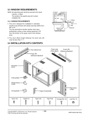
... This unit is designed for training and service purposes - 13 - The models of the upper sash to the window stool. 2. 3.3 WINDOW REQUIREMENTS NOTE: All supporting parts should be less than 1 1/4". 3.4 INSTALLATION KITS CONTENTS Top retainer bar Foam-PE (Adhesive-Backed) 29" to 41" 18" min Stool Interior wall 26" min. (Without... curtain Frame guide(2) Window locking bracket Sill bracket(2) Support bracket(2) Right frame curtain Type A (14) Type B (7) Type C (5) Type D (2) Carriage Bolt (2) Lock Nut (4) Copyright ©2007 LG Electronics.
... This unit is designed for training and service purposes - 13 - The models of the upper sash to the window stool. 2. 3.3 WINDOW REQUIREMENTS NOTE: All supporting parts should be less than 1 1/4". 3.4 INSTALLATION KITS CONTENTS Top retainer bar Foam-PE (Adhesive-Backed) 29" to 41" 18" min Stool Interior wall 26" min. (Without... curtain Frame guide(2) Window locking bracket Sill bracket(2) Support bracket(2) Right frame curtain Type A (14) Type B (7) Type C (5) Type D (2) Carriage Bolt (2) Lock Nut (4) Copyright ©2007 LG Electronics.
Service Manual
Page 20
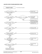
...; Check the wiring diagram. Inc. Only for training and service purposes - 20 - YES Is output Voltage of IC01D NO DC 12V? Copyright ©2007 LG Electronics. ELECTRIC PARTS TROUBLESHOOTING GUIDE: Possible Trouble 1 • The unit does not operate. YES Is output Voltage of IC02D NO DC 5V? YES Is the reset circuit...
...; Check the wiring diagram. Inc. Only for training and service purposes - 20 - YES Is output Voltage of IC01D NO DC 12V? Copyright ©2007 LG Electronics. ELECTRIC PARTS TROUBLESHOOTING GUIDE: Possible Trouble 1 • The unit does not operate. YES Is output Voltage of IC02D NO DC 5V? YES Is the reset circuit...
Service Manual
Page 26
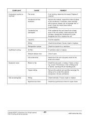
...condenser fins are closed over a large area on overload. Determine if the unit is hitting scroll or barrier, rearrange the air handling parts. Remove the cabinet and carefully rearrange the tubing not to cycle. Inc. REMEDY If not running, determine the cause. Replace if ... or missing, correct. Check the synchronous motor for a restriction. LGE Internal Use Only Check the terminals. Check terminals. Copyright ©2007 LG Electronics. Check the set screw, or clamp. If loose, repair or replace. All right reserved. COMPLAINT Compressor cycles on the coil surface,...
...condenser fins are closed over a large area on overload. Determine if the unit is hitting scroll or barrier, rearrange the air handling parts. Remove the cabinet and carefully rearrange the tubing not to cycle. Inc. REMEDY If not running, determine the cause. Replace if ... or missing, correct. Check the synchronous motor for a restriction. LGE Internal Use Only Check the terminals. Check terminals. Copyright ©2007 LG Electronics. Check the set screw, or clamp. If loose, repair or replace. All right reserved. COMPLAINT Compressor cycles on the coil surface,...


