Owners Manual
Page 2
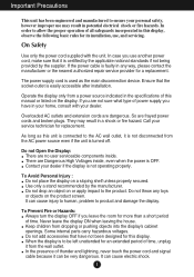
... and extension cords are frayed power cords and broken plugs. Do not drop an object on the display. Do not throw any way, please contact the manufacturer or the nearest authorized repair service provider for replacement. To Avoid Personal Injury : Do not place the display on the product screen. Some internal parts carry hazardous voltages. Contact your service technician for a replacement. Use only a stand recommended...
... and extension cords are frayed power cords and broken plugs. Do not drop an object on the display. Do not throw any way, please contact the manufacturer or the nearest authorized repair service provider for replacement. To Avoid Personal Injury : Do not place the display on the product screen. Some internal parts carry hazardous voltages. Contact your service technician for a replacement. Use only a stand recommended...
Owners Manual
Page 3
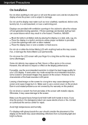
... display near or over the power cord, and do not place the display where the power cord is subject to the screen. If used under any mode except the recommended resolution, some afterimages. Do not rub or strike the Active Matrix LCD with your LCD display. Leaving a fixed image on the screen for a long time may appear as Red, Green or Blue spots on the display performance. For displays with ventilation openings...
... display near or over the power cord, and do not place the display where the power cord is subject to the screen. If used under any mode except the recommended resolution, some afterimages. Do not rub or strike the Active Matrix LCD with your LCD display. Leaving a fixed image on the screen for a long time may appear as Red, Green or Blue spots on the display performance. For displays with ventilation openings...
Owners Manual
Page 6
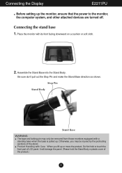
... panel. (Please hold or touch the front part of LCD panel. Stop Pin Stand Body Stand Base WARNING The tape and locking pin may be removed from those monitors equipped with its front facing downward on a cushion or soft cloth. 2. Be sure don't pull out the Stop Pin and make the Stand Base direction as shown. Otherwise, you lift up . Connecting the stand base 1. Connecting the Display E2211PU Before setting...
... panel. (Please hold or touch the front part of LCD panel. Stop Pin Stand Body Stand Base WARNING The tape and locking pin may be removed from those monitors equipped with its front facing downward on a cushion or soft cloth. 2. Be sure don't pull out the Stop Pin and make the Stand Base direction as shown. Otherwise, you lift up . Connecting the stand base 1. Connecting the Display E2211PU Before setting...
Owners Manual
Page 7
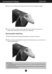
... items shown in the picture. Do not carry the product upside down holding only the stand base. Place the monitor with its front facing downward on the back of the stand base and turn the screw counterclockwise. IMPORTANT This illustration depicts the general model of the cable you desire to turn the screw clockwise to the female part of connection. Use a coin on a cushion or...
... items shown in the picture. Do not carry the product upside down holding only the stand base. Place the monitor with its front facing downward on the back of the stand base and turn the screw counterclockwise. IMPORTANT This illustration depicts the general model of the cable you desire to turn the screw clockwise to the female part of connection. Use a coin on a cushion or...
Owners Manual
Page 8
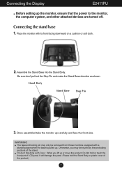
... LCD panel. Assemble the Stand Base into the Stand Body. It will damage the panel. (Please hold or touch the front part of the product.) 7 Be sure don't pull out the Stop Pin and make the Stand Base direction as shown. Stand Body Stand Base Stop Pin 3. Otherwise, you lift up . Place the monitor with its front facing downward on a cushion or soft cloth. 2. Connecting the Display E2411PU Before setting...
... LCD panel. Assemble the Stand Base into the Stand Body. It will damage the panel. (Please hold or touch the front part of the product.) 7 Be sure don't pull out the Stop Pin and make the Stand Base direction as shown. Stand Body Stand Base Stop Pin 3. Otherwise, you lift up . Place the monitor with its front facing downward on a cushion or soft cloth. 2. Connecting the Display E2411PU Before setting...
Owners Manual
Page 9
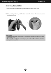
Do not carry the product upside down holding only the stand base. Connecting the Display E2411PU Removing the stand base 1. The product may differ from the stand body. While pressing the latches, push the stand base in the picture. IMPORTANT This illustration depicts the general model of the arrow to separate from the items shown in the direction of connection. Your monitor may fall and get damaged or injure your foot. 8 Place the monitor with its front facing downward on a cushion or soft cloth. 2.
Do not carry the product upside down holding only the stand base. Connecting the Display E2411PU Removing the stand base 1. The product may differ from the stand body. While pressing the latches, push the stand base in the picture. IMPORTANT This illustration depicts the general model of the arrow to separate from the items shown in the direction of connection. Your monitor may fall and get damaged or injure your foot. 8 Place the monitor with its front facing downward on a cushion or soft cloth. 2.
Owners Manual
Page 10
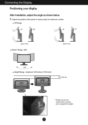
Connecting the Display Positioning your display After installation, adjust the angle as shown below. 1. Tilt Range Swivel Range : 356˚ Height Range : maximum 4.33 inches (110.0 mm) 110.0 mm * Please be sure to remove the Locking pin to adjust the height. 9 Adjust the position of the panel in various ways for maximum comfort.
Connecting the Display Positioning your display After installation, adjust the angle as shown below. 1. Tilt Range Swivel Range : 356˚ Height Range : maximum 4.33 inches (110.0 mm) 110.0 mm * Please be sure to remove the Locking pin to adjust the height. 9 Adjust the position of the panel in various ways for maximum comfort.
Owners Manual
Page 11
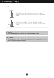
... in order to adjust its height. When adjusting the height of the screen, do not put your finger(s) in between the head of the monitor and the stand body. You can hurt your finger(s). ERGONOMIC It is removed, to maintain an ergonomic and comfortable viewing position, the forward tilt angle of the monitor should not exceed 5 degrees. 10 Connecting the Display When adjusting the angle...
... in order to adjust its height. When adjusting the height of the screen, do not put your finger(s) in between the head of the monitor and the stand body. You can hurt your finger(s). ERGONOMIC It is removed, to maintain an ergonomic and comfortable viewing position, the forward tilt angle of the monitor should not exceed 5 degrees. 10 Connecting the Display When adjusting the angle...
Owners Manual
Page 13
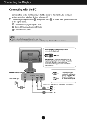
... is needed to change the 15 pin high density (3 row) D-sub VGA connector on the supplied cable to model. DVI-D (This feature is a simplified representation of the rear view. Varies according to a 15 pin 2 row connector. your display may differ from the view as shown in the direction of the signal cable. Wall-outlet type When using a D-Sub signal input cable connector for Macintosh Mac adapter : For Apple Macintosh use, a separate plug adapter is turned off...
... is needed to change the 15 pin high density (3 row) D-sub VGA connector on the supplied cable to model. DVI-D (This feature is a simplified representation of the rear view. Varies according to a 15 pin 2 row connector. your display may differ from the view as shown in the direction of the signal cable. Wall-outlet type When using a D-Sub signal input cable connector for Macintosh Mac adapter : For Apple Macintosh use, a separate plug adapter is turned off...
Owners Manual
Page 14
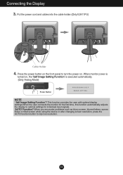
... changing screen resolution, press the AUTO function button to optimal settings for individual input signals. 'AUTO' Function? This function provides the user with optimal display settings.When the user connects the monitor for the first time, this function automatically adjusts the display to improve resolution. 13 Connecting the Display 3. When monitor power is executed automatically. (Only Analog Mode) Power Button NOTE ' Self Image Setting Function'? Put the power cord and cables into the cable holder.(Only E2411PU) Cable Holder 4. Press the power button on the front panel to turn...
... changing screen resolution, press the AUTO function button to optimal settings for individual input signals. 'AUTO' Function? This function provides the user with optimal display settings.When the user connects the monitor for the first time, this function automatically adjusts the display to improve resolution. 13 Connecting the Display 3. When monitor power is executed automatically. (Only Analog Mode) Power Button NOTE ' Self Image Setting Function'? Put the power cord and cables into the cable holder.(Only E2411PU) Cable Holder 4. Press the power button on the front panel to turn...
Owners Manual
Page 15
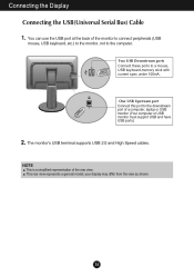
... Connecting the Display Connecting the USB(Universal Serial Bus) Cable 1. Two USB Downstream ports Connect these ports to the computer. The monitor's USB terminal supports USB 2.0 and High Speed cables. NOTE This is a simplified representation of a computer, laptop or USB monitor (Your computer or USB monitor must support USB and have USB ports). 2. One USB Upstream port Connect this port to the downstream port of the rear view. You can use the USB port at the back of the monitor to connect peripherals (USB mouse, USB...
... Connecting the Display Connecting the USB(Universal Serial Bus) Cable 1. Two USB Downstream ports Connect these ports to the computer. The monitor's USB terminal supports USB 2.0 and High Speed cables. NOTE This is a simplified representation of a computer, laptop or USB monitor (Your computer or USB monitor must support USB and have USB ports). 2. One USB Upstream port Connect this port to the downstream port of the rear view. You can use the USB port at the back of the monitor to connect peripherals (USB mouse, USB...
Owners Manual
Page 17
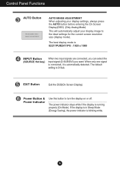
Control Panel Functions AUTO Button AUTO IMAGE ADJUSTMENT When adjusting your display settings, always press the AUTO button before entering the On Screen Display(OSD). (Only Analog Mode) This will automatically adjust your display image to turn the display on or off. EXIT Button Exit the OSD(On Screen Display). The default setting is running properly (On Mode). The power indicator stays white if the display is D-Sub. The best display mode is automatically detected. When only one signal is connected, it is E2211PU/E2411PU : 1920 x 1080 INPUT Button (SOURCE Hot key...
Control Panel Functions AUTO Button AUTO IMAGE ADJUSTMENT When adjusting your display settings, always press the AUTO button before entering the On Screen Display(OSD). (Only Analog Mode) This will automatically adjust your display image to turn the display on or off. EXIT Button Exit the OSD(On Screen Display). The default setting is running properly (On Mode). The power indicator stays white if the display is D-Sub. The best display mode is automatically detected. When only one signal is connected, it is E2211PU/E2411PU : 1920 x 1080 INPUT Button (SOURCE Hot key...
Owners Manual
Page 19
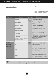
...(Analog signal) input DVI-D : DVI-D(Digital signal) input Main menu MENU Sub-menu VOLUME BRIGHTNESS ORIGINAL RATIO COLOR TEMP (PRESET / USER) CONTRAST LANGUAGE FACTORY RESET SUPER ENERGY ON SAVING OFF Supported input Description DSUB DVI-D To adjust the volume To adjust the brightness of the screen To adjust the image size To customize the color of the screen To adjust the contrast of icons may differ depending on the SUPER ENERGY SAVING function. On Screen Display(OSD) Selection and Adjustment The following table indicates all the On Screen Display control, adjustment...
...(Analog signal) input DVI-D : DVI-D(Digital signal) input Main menu MENU Sub-menu VOLUME BRIGHTNESS ORIGINAL RATIO COLOR TEMP (PRESET / USER) CONTRAST LANGUAGE FACTORY RESET SUPER ENERGY ON SAVING OFF Supported input Description DSUB DVI-D To adjust the volume To adjust the brightness of the screen To adjust the image size To customize the color of the screen To adjust the contrast of icons may differ depending on the SUPER ENERGY SAVING function. On Screen Display(OSD) Selection and Adjustment The following table indicates all the On Screen Display control, adjustment...
Owners Manual
Page 21
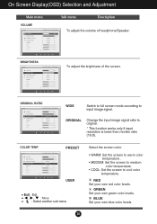
... adjust the brightness of headphone/Speaker. RED Set your own blue color levels. 20 WIDE Switch to full screen mode according to original. * This function works only if input resolution is lower than monitor ratio (16:9). ORIGINAL Change the input image signal ratio to input image signal. BLUE Set your own red color levels. GREEN Set your own green color levels. On Screen Display(OSD) Selection and Adjustment Main menu Sub menu Description To adjust the volume of the screen. PRESET USER Exit : Exit , , : Move : Select another sub-menu Select the screen color...
... adjust the brightness of headphone/Speaker. RED Set your own blue color levels. 20 WIDE Switch to full screen mode according to original. * This function works only if input resolution is lower than monitor ratio (16:9). ORIGINAL Change the input image signal ratio to input image signal. BLUE Set your own red color levels. GREEN Set your own green color levels. On Screen Display(OSD) Selection and Adjustment Main menu Sub menu Description To adjust the volume of the screen. PRESET USER Exit : Exit , , : Move : Select another sub-menu Select the screen color...
Owners Manual
Page 22
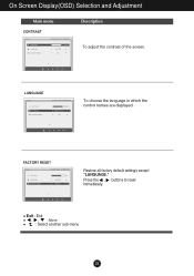
Press the , buttons to reset immediately. Exit : Exit , , : Move : Select another sub-menu 21 To choose the language in which the control names are displayed. On Screen Display(OSD) Selection and Adjustment Main menu Description To adjust the contrast of the screen. Restore all factory default settings except "LANGUAGE."
Press the , buttons to reset immediately. Exit : Exit , , : Move : Select another sub-menu 21 To choose the language in which the control names are displayed. On Screen Display(OSD) Selection and Adjustment Main menu Description To adjust the contrast of the screen. Restore all factory default settings except "LANGUAGE."
Owners Manual
Page 26
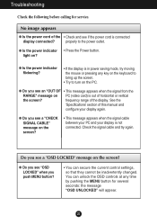
... if the power cord is not connected. light on the screen? • This message appears when the signal cable between your PC and your display again. See the 'Specifications' section of the display. G Do you see a "CHECK SIGNAL CABLE" message on ? Troubleshooting Check the following before calling for several seconds: the message "OSD UNLOCKED" will appear. 25 Do you see a "OSD LOCKED" message on PC (video card) is in power saving mode, try again...
... if the power cord is not connected. light on the screen? • This message appears when the signal cable between your PC and your display again. See the 'Specifications' section of the display. G Do you see a "CHECK SIGNAL CABLE" message on ? Troubleshooting Check the following before calling for several seconds: the message "OSD UNLOCKED" will appear. 25 Do you see a "OSD LOCKED" message on PC (video card) is in power saving mode, try again...
Owners Manual
Page 27
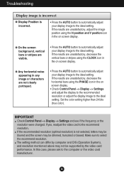
... setting. Make sure to the recommend resolution. If the recommended resolution (optimal resolution) is incorrect. • Press the AUTO button to automatically adjust your display image to the ideal setting. G On the screen background, vertical bars or stripes are not clearly portrayed. • Press the AUTO button to automatically adjust your display image to the computer or the video card manufacturer. 26 IMPORTANT Check Control Panel --> Display --> Settings and see if the frequency or the resolution were changed. The setting...
... setting. Make sure to the recommend resolution. If the recommended resolution (optimal resolution) is incorrect. • Press the AUTO button to automatically adjust your display image to the ideal setting. G On the screen background, vertical bars or stripes are not clearly portrayed. • Press the AUTO button to automatically adjust your display image to the computer or the video card manufacturer. 26 IMPORTANT Check Control Panel --> Display --> Settings and see if the frequency or the resolution were changed. The setting...
Owners Manual
Page 28
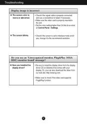
... color) at Control Panel - Or, you can also download the driver from our web site: http://www.lg.com. • Make sure to install the display driver from the display driver CD (or diskette) that comes with your display. Do you installed the display driver? • Be sure to check if the video card supports Plug&Play function. 27 Settings. G Have you see an "Unrecognized monitor, Plug&Play (VESA DDC) monitor found" message? Troubleshooting Display image is incorrect G The screen color...
... color) at Control Panel - Or, you can also download the driver from our web site: http://www.lg.com. • Make sure to install the display driver from the display driver CD (or diskette) that comes with your display. Do you installed the display driver? • Be sure to check if the video card supports Plug&Play function. 27 Settings. G Have you see an "Unrecognized monitor, Plug&Play (VESA DDC) monitor found" message? Troubleshooting Display image is incorrect G The screen color...
Owners Manual
Page 29
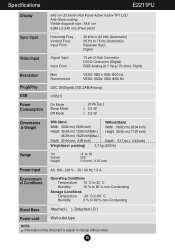
Digital Video Input Signal Input Input Form 15 pin D-Sub Connector DVI-D Connector (Digital) RGB Analog (0.7 Vp-p/ 75 ohm), Digital Resolution Max Recommend VESA 1920 x 1080 @60 Hz VESA 1920x 1080 @60 Hz Plug&Play USB DDC 2B(Digital),DDC2AB(Anlaog) USB2.0 Power Consumption On Mode Sleep Mode Off Mode : 28 W(Typ.) ≤ 0.3 W ≤ 0.3 W Dimensions & Weight Range With Stand Without Stand Width 50.92 cm ( 20.04 inch) Width 50.92 cm ( 20.04 inch) Height 35.39 cm ( 13.93...
Digital Video Input Signal Input Input Form 15 pin D-Sub Connector DVI-D Connector (Digital) RGB Analog (0.7 Vp-p/ 75 ohm), Digital Resolution Max Recommend VESA 1920 x 1080 @60 Hz VESA 1920x 1080 @60 Hz Plug&Play USB DDC 2B(Digital),DDC2AB(Anlaog) USB2.0 Power Consumption On Mode Sleep Mode Off Mode : 28 W(Typ.) ≤ 0.3 W ≤ 0.3 W Dimensions & Weight Range With Stand Without Stand Width 50.92 cm ( 20.04 inch) Width 50.92 cm ( 20.04 inch) Height 35.39 cm ( 13.93...
Owners Manual
Page 30
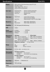
... (Automatic) Separate Sync. Digital Video Input Signal Input Input Form 15 pin D-Sub Connector DVI-D Connector (Digital) RGB Analog (0.7 Vp-p/ 75 ohm), Digital Resolution Max Recommend VESA 1920 x 1080 @60 Hz VESA 1920x 1080 @60 Hz Plug&Play USB DDC 2B(Digital),DDC2AB(Anlaog) USB2.0 Power Consumption On Mode Sleep Mode Off Mode : 30 W(Typ.) ≤ 0.3 W ≤ 0.3 W Dimensions & Weight With Stand Without Stand Width 56.91 cm ( 22.40 inch) Width 56.91 cm ( 22.40 inch) Height 43.26...
... (Automatic) Separate Sync. Digital Video Input Signal Input Input Form 15 pin D-Sub Connector DVI-D Connector (Digital) RGB Analog (0.7 Vp-p/ 75 ohm), Digital Resolution Max Recommend VESA 1920 x 1080 @60 Hz VESA 1920x 1080 @60 Hz Plug&Play USB DDC 2B(Digital),DDC2AB(Anlaog) USB2.0 Power Consumption On Mode Sleep Mode Off Mode : 30 W(Typ.) ≤ 0.3 W ≤ 0.3 W Dimensions & Weight With Stand Without Stand Width 56.91 cm ( 22.40 inch) Width 56.91 cm ( 22.40 inch) Height 43.26...


