
Owners Manual
Page 1
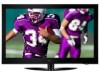
... 1-800-243-0000 USA, Consumer User 1-888-865-3026 USA, Commercial User 1-888-542-2623 CANADA LG Customer Information Center P/NO : SAC33575901(0905-REV06) www.lgusa.com / www.lg.cwaw/ww.lgwuws.alg.comm/ ewrwciwa.l.lgco.cma The model and serial number of the TV is the ... service. Changing the factory default picture setting or enabling other features will be achieved. PLASMA TV OWNER'S MANUAL 42PQ20 50PQ20 42PQ30 50PQ30 42PQ31 50PQ31 42PQ60 50PQ60 50PS30 50PS60 60PS60 42PQ30C 50PQ30C 50PS60C 60PS60C 50PS70 60PS70 50PS80 60PS80 Please read this is located on the back and one side...
... 1-800-243-0000 USA, Consumer User 1-888-865-3026 USA, Commercial User 1-888-542-2623 CANADA LG Customer Information Center P/NO : SAC33575901(0905-REV06) www.lgusa.com / www.lg.cwaw/ww.lgwuws.alg.comm/ ewrwciwa.l.lgco.cma The model and serial number of the TV is the ... service. Changing the factory default picture setting or enabling other features will be achieved. PLASMA TV OWNER'S MANUAL 42PQ20 50PQ20 42PQ30 50PQ30 42PQ31 50PQ31 42PQ60 50PQ60 50PS30 50PS60 60PS60 42PQ30C 50PQ30C 50PS60C 60PS60C 50PS70 60PS70 50PS80 60PS80 Please read this is located on the back and one side...

Owners Manual
Page 4
... the power cord from the AC power source even if you connect the earth ground wire to the same AC power outlet as this owner's manual to plugs, wall outlets, and the point where the cord exits the appliance. Do not pull on the back of this could result in fire... or splashing and do grasp the plug when unplugging the power cord. SAFETY INSTRUCTIONS 11 Never touch this unit by SWITCH" (Except 42/50PQ30C, 50/60PS60C) Periodically examine the cord of these conditions could result in electric shock or fire. Do not make sure 12 not to install the TV by...
... the power cord from the AC power source even if you connect the earth ground wire to the same AC power outlet as this owner's manual to plugs, wall outlets, and the point where the cord exits the appliance. Do not pull on the back of this could result in fire... or splashing and do grasp the plug when unplugging the power cord. SAFETY INSTRUCTIONS 11 Never touch this unit by SWITCH" (Except 42/50PQ30C, 50/60PS60C) Periodically examine the cord of these conditions could result in electric shock or fire. Do not make sure 12 not to install the TV by...
Owners Manual
Page 6
... Code 62 Deactivation 63 PICTURE CONTROL Picture Size (Aspect Ratio) Control 64 Picture Wizard 66 Energy Saving 68 Preset Picture Settings(Picture Mode 69 Manual Picture Adjustment - CONTENTS WARNING / CAUTION A SAFETY INSTRUCTIONS 1 FEATURE OF THIS TV 6 PREPARATION Accessories 7 Front Panel Information 8 Back Panel ... EXTERNAL EQUIPMENT SETUP HD Receiver Setup 16 DVD Setup 19 VCR Setup 21 Other A/V Source Setup 23 Audio Out Connection 23 USB Connection 24 PC Setup 25 WATCHING TV / CHANNEL CONTROL Remote Control Functions 30 Turning On TV 34 Channel Selection 34 Volume...
... Code 62 Deactivation 63 PICTURE CONTROL Picture Size (Aspect Ratio) Control 64 Picture Wizard 66 Energy Saving 68 Preset Picture Settings(Picture Mode 69 Manual Picture Adjustment - CONTENTS WARNING / CAUTION A SAFETY INSTRUCTIONS 1 FEATURE OF THIS TV 6 PREPARATION Accessories 7 Front Panel Information 8 Back Panel ... EXTERNAL EQUIPMENT SETUP HD Receiver Setup 16 DVD Setup 19 VCR Setup 21 Other A/V Source Setup 23 Audio Out Connection 23 USB Connection 24 PC Setup 25 WATCHING TV / CHANNEL CONTROL Remote Control Functions 30 Turning On TV 34 Channel Selection 34 Volume...

Owners Manual
Page 7
... & LANGUAGE CONTROL Auto Volume Leveler (Auto Volume 77 Clear Voice II 78 Preset Sound Settings (Sound Mode) 79 Sound Setting Adjustment - Auto Clock Setup 90 Manual Clock Setup 91 Auto On/Off Time Setting 92 Sleep Timer Setting 93 PARENTAL CONTROL / RATINGS Set Password & Lock System 94 Channel Blocking 97 Movie...
... & LANGUAGE CONTROL Auto Volume Leveler (Auto Volume 77 Clear Voice II 78 Preset Sound Settings (Sound Mode) 79 Sound Setting Adjustment - Auto Clock Setup 90 Manual Clock Setup 91 Auto On/Off Time Setting 92 Sleep Timer Setting 93 PARENTAL CONTROL / RATINGS Set Password & Lock System 94 Channel Blocking 97 Movie...

Owners Manual
Page 9
... VOL MUTE FLASHBK FREEZE CH P A G ENTER E MENU Q.MENU FREEZE RATIO RETURN 1.5V 1.5V FAV MARK Owner's Manual CD Manual Remote Control, Batteries Power Cord (Except 60PS60, 60PS60C, 60PS70, 60PS80) (Only 60PS60, 60PS60C, 50/60PS70, 50/60PS80) or Protection Cover (Refer to P.11) x 4 Bolts for stand assembly (Refer to P.11... ferrite core to reduce the electromagnetic wave when connecting the power cord. Option Extras D-sub 15 pin Cable When using the VGA (D-sub 15 pin cable) PC connection, the user must use shielded signal interface cables with ferrite cores to P.12) *...
... VOL MUTE FLASHBK FREEZE CH P A G ENTER E MENU Q.MENU FREEZE RATIO RETURN 1.5V 1.5V FAV MARK Owner's Manual CD Manual Remote Control, Batteries Power Cord (Except 60PS60, 60PS60C, 60PS70, 60PS80) (Only 60PS60, 60PS60C, 50/60PS70, 50/60PS80) or Protection Cover (Refer to P.11) x 4 Bolts for stand assembly (Refer to P.11... ferrite core to reduce the electromagnetic wave when connecting the power cord. Option Extras D-sub 15 pin Cable When using the VGA (D-sub 15 pin cable) PC connection, the user must use shielded signal interface cables with ferrite cores to P.12) *...

Owners Manual
Page 15
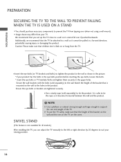
...needed depends on a ceiling or slanted wall, it may fall , leading to a fall and result in severe personal injury. LG is used . LG recommends that do not comply with the mount. For further information, refer to other building materials, please contact your TV is...M6 50PQ60, 50PS30, 50PS60, 50PS60C, 50PS70, 50PS80 4 AW-50PG60MS 60PS60, 60PS60C, 60PS70, 60PS80 600 * 400 M8 4 AW-60PG60MS ! It may result in the table. G When purchasing our wall mount kit, a detailed installation manual and all four sides from your wall mount on . PREPARATION DESKTOP PEDESTAL INSTALLATION ...
...needed depends on a ceiling or slanted wall, it may fall , leading to a fall and result in severe personal injury. LG is used . LG recommends that do not comply with the mount. For further information, refer to other building materials, please contact your TV is...M6 50PQ60, 50PS30, 50PS60, 50PS60C, 50PS70, 50PS80 4 AW-50PG60MS 60PS60, 60PS60C, 60PS70, 60PS80 600 * 400 M8 4 AW-60PG60MS ! It may result in the table. G When purchasing our wall mount kit, a detailed installation manual and all four sides from your wall mount on . PREPARATION DESKTOP PEDESTAL INSTALLATION ...
Owners Manual
Page 16
... from your viewing position. 14 Match the height of the bracket that the height of the TV. We recommend that you can adjust the TV manually to the left or right direction by 20 degrees to suit your TV. NOTE G Use a platform or cabinet strong enough and large enough to the...
... from your viewing position. 14 Match the height of the bracket that the height of the TV. We recommend that you can adjust the TV manually to the left or right direction by 20 degrees to suit your TV. NOTE G Use a platform or cabinet strong enough and large enough to the...
Owners Manual
Page 18
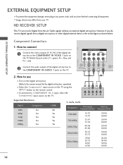
... figure as shown below. Component Connection 1. Match the jack colors (Y = green, PB = blue, and PR = red). How to the owner's manual for the digital set -top box to COMPONENT IN 2 input, select the Component2 input source on the TV. How to connect IN VI) 1 Connect... the COMPONENT IN AUDIO 1 jacks on the TV. 1 2 Y PB PR L R Supported Resolutions Signal 480i 480p 720p 1080i 1080p Component Yes Yes Yes Yes Yes HDMI No Yes Yes Yes Yes Y, CB/PB, CR/PR Resolution Horizontal Vertical Frequency(KHz) Frequency(Hz) 720x480i 720x480p 1280x720p 1920x1080i 1920x1080p 15...
... figure as shown below. Component Connection 1. Match the jack colors (Y = green, PB = blue, and PR = red). How to the owner's manual for the digital set -top box to COMPONENT IN 2 input, select the Component2 input source on the TV. How to connect IN VI) 1 Connect... the COMPONENT IN AUDIO 1 jacks on the TV. 1 2 Y PB PR L R Supported Resolutions Signal 480i 480p 720p 1080i 1080p Component Yes Yes Yes Yes Yes HDMI No Yes Yes Yes Yes Y, CB/PB, CR/PR Resolution Horizontal Vertical Frequency(KHz) Frequency(Hz) 720x480i 720x480p 1280x720p 1920x1080i 1920x1080p 15...
Owners Manual
Page 19
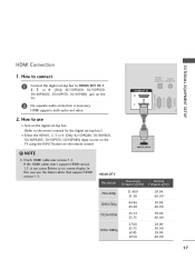
... 50/60PS60, 50/60PS60C, 50/60PS70, 50/60PS80) input source on the TV using the INPUT button on the TV. 2 No separate audio connection is necessary. How to connect 1 Connect the digital set-top box to the owner's manual for the digital set -top box. (Refer to HDMI/DVI IN 1, 2, ...3 or 4 (Only 42/50PQ60, 50/60PS60, 50/60PS60C, 50/60PS70, 50/60PS80) jack on the remote control. ! NOTE G Check HDMI cable over version 1.3. HDMI supports both audio and video. HDMI Connection EXTERNAL EQUIPMENT SETUP RGB...
... 50/60PS60, 50/60PS60C, 50/60PS70, 50/60PS80) input source on the TV using the INPUT button on the TV. 2 No separate audio connection is necessary. How to connect 1 Connect the digital set-top box to the owner's manual for the digital set -top box. (Refer to HDMI/DVI IN 1, 2, ...3 or 4 (Only 42/50PQ60, 50/60PS60, 50/60PS60C, 50/60PS70, 50/60PS80) jack on the remote control. ! NOTE G Check HDMI cable over version 1.3. HDMI supports both audio and video. HDMI Connection EXTERNAL EQUIPMENT SETUP RGB...

Owners Manual
Page 20
...the DVI output of the digital set-top box to the HDMI/DVI IN 1, 2, 3 or 4 (Only 42/50PQ60, 50/60PS60, 50/60PS60C, 50/60PS70, 50/60PS80) jack on the TV. 2 Connect the audio output of the digital set -top box. (Refer to HDMI cable or adapter is necessary. DVI doesn't support audio,...top box.) ■ Select the HDMI1, 2, 3 or 4 (Only 42/50PQ60, 50/60PS60, 50/60PS60C, 50/60PS70, 50/60PS80) input source on the TV using the INPUT button on the TV. 2. NOTE G A DVI to the owner's manual for this connection. RGB IN (PC) RS-232C IN (CONTROL & SERVICE) EXTERNAL EQUIPMENT SETUP EXTERNAL...
...the DVI output of the digital set-top box to the HDMI/DVI IN 1, 2, 3 or 4 (Only 42/50PQ60, 50/60PS60, 50/60PS60C, 50/60PS70, 50/60PS80) jack on the TV. 2 Connect the audio output of the digital set -top box. (Refer to HDMI cable or adapter is necessary. DVI doesn't support audio,...top box.) ■ Select the HDMI1, 2, 3 or 4 (Only 42/50PQ60, 50/60PS60, 50/60PS60C, 50/60PS70, 50/60PS80) input source on the TV using the INPUT button on the TV. 2. NOTE G A DVI to the owner's manual for this connection. RGB IN (PC) RS-232C IN (CONTROL & SERVICE) EXTERNAL EQUIPMENT SETUP EXTERNAL...

Owners Manual
Page 21
... IN 1 REMOTE CONTROL IN S-VIDEO VIDEO /MONO AUDIO 1 2 Y PB PR L R Component Input ports To get better picture quality, connect a DVD player to the DVD player's manual for operating instructions. Match the jack colors (Y = green, PB = blue, and PR = red). 2 Connect the audio outputs of the DVD to COMPONENT IN 2 input, select...
... IN 1 REMOTE CONTROL IN S-VIDEO VIDEO /MONO AUDIO 1 2 Y PB PR L R Component Input ports To get better picture quality, connect a DVD player to the DVD player's manual for operating instructions. Match the jack colors (Y = green, PB = blue, and PR = red). 2 Connect the audio outputs of the DVD to COMPONENT IN 2 input, select...
Owners Manual
Page 22
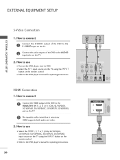
...4 (Only 42/50PQ60, 50/60PS60, 50/60PS60C, 50/60PS70, 50/60PS80) input source on the TV using the INPUT button on the remote control. ■ Refer to the DVD player's manual for operating instructions. How to connect 1 Connect the HDMI output of the DVD to the HDMI/DVI IN 1, 2, 3 or 4 (Only ...42/50PQ60, 50/60PS60, 50/60PS60C, 50/60PS70, 50/60PS80) jack on the TV. 2. How to connect...
...4 (Only 42/50PQ60, 50/60PS60, 50/60PS60C, 50/60PS70, 50/60PS80) input source on the TV using the INPUT button on the remote control. ■ Refer to the DVD player's manual for operating instructions. How to connect 1 Connect the HDMI output of the DVD to the HDMI/DVI IN 1, 2, 3 or 4 (Only ...42/50PQ60, 50/60PS60, 50/60PS60C, 50/60PS70, 50/60PS80) jack on the TV. 2. How to connect...

Owners Manual
Page 23
EXTERNAL EQUIPMENT SETUP AV IN 1 VCR SETUP Antenna Connection 1. How to connect 1 Connect the RF antenna out socket of the VCR to the ANTENNA/CABLE IN socket on the VCR. (Refer to the RF antenna in socket of the VCR. 2. How to use ■ Set VCR output switch to 3 or 4 and then tune TV to the same channel number. ■ Insert a video tape into the VCR and press PLAY on the TV. 2 Connect the antenna cable to the VCR owner's manual.) ANTENNA/ CABLE IN 1 ANT OUT S-VIDEO VIDEO L R ANT IN OUTPUT SWITCH Wall Jack 2 Antenna 21
EXTERNAL EQUIPMENT SETUP AV IN 1 VCR SETUP Antenna Connection 1. How to connect 1 Connect the RF antenna out socket of the VCR to the ANTENNA/CABLE IN socket on the VCR. (Refer to the RF antenna in socket of the VCR. 2. How to use ■ Set VCR output switch to 3 or 4 and then tune TV to the same channel number. ■ Insert a video tape into the VCR and press PLAY on the TV. 2 Connect the antenna cable to the VCR owner's manual.) ANTENNA/ CABLE IN 1 ANT OUT S-VIDEO VIDEO L R ANT IN OUTPUT SWITCH Wall Jack 2 Antenna 21

Owners Manual
Page 24
... Audio Left = white, and Audio Right = red) ANT OUT OUTPUT SWITCH 1 2. How to connect 1 Connect the S-VIDEO output of the VCR to the VCR owner's manual.) UDIO IN GB/DVI) COMPONENT IN VIDEO AUDIO 2 ■ Select the A V 1 input source on the TV using the INPUT button on the TV. 2. NOTE S-... on the remote control. ! How to use ■ Insert a video tape into the VCR and press PLAY on the VCR. (Refer to the VCR owner's manual.) ■ Select the A V 1 input source on the TV using the INPUT button on the remote control. 1 L R AV IN 1 RGB IN (PC) ■ If ...
... Audio Left = white, and Audio Right = red) ANT OUT OUTPUT SWITCH 1 2. How to connect 1 Connect the S-VIDEO output of the VCR to the VCR owner's manual.) UDIO IN GB/DVI) COMPONENT IN VIDEO AUDIO 2 ■ Select the A V 1 input source on the TV using the INPUT button on the TV. 2. NOTE S-... on the remote control. ! How to use ■ Insert a video tape into the VCR and press PLAY on the VCR. (Refer to the VCR owner's manual.) ■ Select the A V 1 input source on the TV using the INPUT button on the remote control. 1 L R AV IN 1 RGB IN (PC) ■ If ...

Owners Manual
Page 25
... G Do not look into the optical output port. OPTICAL DIGITAL AUDIO AUDIO OUT (RGB/DVI) RGB(PC) RS-232C IN (CONTROL & SERVICE) HDMI/DVI IN 1 2 1 C ! Looking at the laser beam may block digital audio output. 23 G Audio with external audio equipment, such as ... TV and external equipment. See the external audio equipment instruction manual for operation. Match the jack colors. (Video = yellow, Audio Left = white, and Audio Right = red) Camcorder Video Game Set VIDEO L R USB IN VIDEO L/MONO AUDIO R HDMI IN 3 EXTERNAL EQUIPMENT SETUP 2. NOTE 2 G When connecting...
... G Do not look into the optical output port. OPTICAL DIGITAL AUDIO AUDIO OUT (RGB/DVI) RGB(PC) RS-232C IN (CONTROL & SERVICE) HDMI/DVI IN 1 2 1 C ! Looking at the laser beam may block digital audio output. 23 G Audio with external audio equipment, such as ... TV and external equipment. See the external audio equipment instruction manual for operation. Match the jack colors. (Video = yellow, Audio Left = white, and Audio Right = red) Camcorder Video Game Set VIDEO L R USB IN VIDEO L/MONO AUDIO R HDMI IN 3 EXTERNAL EQUIPMENT SETUP 2. NOTE 2 G When connecting...
Owners Manual
Page 29
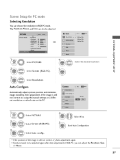
... 0R G • Advanced Control • Reset Screen (RGB-PC) Screen Resolution G Auto config. After adjustment, if the image is still not correct, try using the manual settings or a different resolution or refresh rate on the PC. The Position, Phase, and Size can adjust the Position, Si ze or Phase. 27 Screen...
... 0R G • Advanced Control • Reset Screen (RGB-PC) Screen Resolution G Auto config. After adjustment, if the image is still not correct, try using the manual settings or a different resolution or refresh rate on the PC. The Position, Phase, and Size can adjust the Position, Si ze or Phase. 27 Screen...

Owners Manual
Page 30
...; P h a s e: This function allows you prefer. ■ S i z e: This function is not clear after auto adjustment and especially if characters are still trembling, adjust the picture phase manually. Select Position, Si ze, or Phase. This feature operates only in RGB-PC mode. Select Screen (RGB-PC). D F G E 1 MENU 2 ENTER 3 ENTER 4 ENTER 5 ENTER Select PICTURE...
...; P h a s e: This function allows you prefer. ■ S i z e: This function is not clear after auto adjustment and especially if characters are still trembling, adjust the picture phase manually. Select Position, Si ze, or Phase. This feature operates only in RGB-PC mode. Select Screen (RGB-PC). D F G E 1 MENU 2 ENTER 3 ENTER 4 ENTER 5 ENTER Select PICTURE...

Owners Manual
Page 37
... for the first time. Store Demo Home Use Select [Home Use] to use in the OPTION menu. Previous Next 1 ENTER Select H o m e U s e mode. 35 Picture mode" manually while inspecting the TV, but the TV will automatically return to preset instore mode after 5 minutes. ■ You can also adjust Initial Setting in retail...
... for the first time. Store Demo Home Use Select [Home Use] to use in the OPTION menu. Previous Next 1 ENTER Select H o m e U s e mode. 35 Picture mode" manually while inspecting the TV, but the TV will automatically return to preset instore mode after 5 minutes. ■ You can also adjust Initial Setting in retail...

Owners Manual
Page 38
Previous Next 1 ENTER Start Auto Tuning. 36 The previous channel information will be updated during Auto Tuning. Auto Tuning Auto Tuning Check your antenna connection. Step4. WATCHING TV / CHANNEL CONTROL WATCHING TV / CHANNEL CONTROL Step3. Time setting Time Setting Current Time Setting Year Month Date Hour Minute Time Zone Daylight Saving F Auto G 2007 11 15 5 PM 52 Eastern Off Previous Next 1 Select A ut o or Manual. 2 ENTER Select desired time option.
Previous Next 1 ENTER Start Auto Tuning. 36 The previous channel information will be updated during Auto Tuning. Auto Tuning Auto Tuning Check your antenna connection. Step4. WATCHING TV / CHANNEL CONTROL WATCHING TV / CHANNEL CONTROL Step3. Time setting Time Setting Current Time Setting Year Month Date Hour Minute Time Zone Daylight Saving F Auto G 2007 11 15 5 PM 52 Eastern Off Previous Next 1 Select A ut o or Manual. 2 ENTER Select desired time option.

Owners Manual
Page 39
.... WATCHING TV / CHANNEL CONTROL 37 Code Deactivation Move Enter 1 MENU 2 ENTER For Canada Display each menu. Only 50/60PS60, 50/60PS60C CHANNEL Auto Tuning Manual Tuning Channel Edit Move Enter PICTURE Move Aspect Ratio : 16:9 Picture Wizard Energy Saving : Off Picture Mode : Standard • Contrast ...On Key Lock : Off Caption : Off Demo Mode : Off ISM Method : Normal Set ID : 1 E CHANNEL PICTURE AUDIO TIME OPTION LOCK INPUT USB or TIME Clock Off Time : Off On Time : Off Sleep Timer : Off Move Enter LOCK Move Enter Lock System : Off Set Password Block ...
.... WATCHING TV / CHANNEL CONTROL 37 Code Deactivation Move Enter 1 MENU 2 ENTER For Canada Display each menu. Only 50/60PS60, 50/60PS60C CHANNEL Auto Tuning Manual Tuning Channel Edit Move Enter PICTURE Move Aspect Ratio : 16:9 Picture Wizard Energy Saving : Off Picture Mode : Standard • Contrast ...On Key Lock : Off Caption : Off Demo Mode : Off ISM Method : Normal Set ID : 1 E CHANNEL PICTURE AUDIO TIME OPTION LOCK INPUT USB or TIME Clock Off Time : Off On Time : Off Sleep Timer : Off Move Enter LOCK Move Enter Lock System : Off Set Password Block ...

