Owners Manual
Page 3
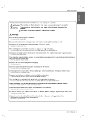
... the wall outlet before moving the set . - WARNING The violation of the screen. - NOTES Never touch the power plug with speakers do not carry holding the speakers. - This may cause the set . In case that may cause light injuries or damage of this product from eating them , take the person to keep the former from the mains power and remove all connections before cleaning. This...
... the wall outlet before moving the set . - WARNING The violation of the screen. - NOTES Never touch the power plug with speakers do not carry holding the speakers. - This may cause the set . In case that may cause light injuries or damage of this product from eating them , take the person to keep the former from the mains power and remove all connections before cleaning. This...
Owners Manual
Page 5
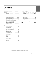
... watching HDMI/DVI/RGB from the VCR/DVD/Set-top Box (480p/576p/720p/1080i 15 Watching AV Outputs 16 Operation Turning on the Monitor 17 Menu Language Selection 17 Picture Menu Options PSM (Picture Status Memory 18 Manual Picture Control (user option 18 CSM (Colour Status Memory 18 Manual Colour Temperature Control 19 XD 19 Advanced - ENGLISH Contents Contents Safety Instructions 2~4 Introduction Accessories 7 Controls and Connection Options 8~9 Remote Control Key Functions 10 Installation Installation Instructions...
... watching HDMI/DVI/RGB from the VCR/DVD/Set-top Box (480p/576p/720p/1080i 15 Watching AV Outputs 16 Operation Turning on the Monitor 17 Menu Language Selection 17 Picture Menu Options PSM (Picture Status Memory 18 Manual Picture Control (user option 18 CSM (Colour Status Memory 18 Manual Colour Temperature Control 19 XD 19 Advanced - ENGLISH Contents Contents Safety Instructions 2~4 Introduction Accessories 7 Controls and Connection Options 8~9 Remote Control Key Functions 10 Installation Installation Instructions...

Owners Manual
Page 8
... different from your set on from standby or off to standby. 60PM4M VOLUME (F,G) Buttons INPUT SELECT Button 8 Plasma Monitor INPUT SELECT VOLUME INPUT SELECT VOLUME Remote Control Sensor Power Standby Indicator Illuminates red in standby mode, Illuminates green when the Set is turned on . 4. Front Panel Controls 3 4 5 6 12 7 1. Main Power Button Switches the set . Introduction Controls - MENU Button 2. Remote Control Sensor 6. E, D Buttons 7. Power Indicator Illuminates red in standby mode, Illuminates green when the Monitor is turned on Sub power button
... different from your set on from standby or off to standby. 60PM4M VOLUME (F,G) Buttons INPUT SELECT Button 8 Plasma Monitor INPUT SELECT VOLUME INPUT SELECT VOLUME Remote Control Sensor Power Standby Indicator Illuminates red in standby mode, Illuminates green when the Set is turned on . 4. Front Panel Controls 3 4 5 6 12 7 1. Main Power Button Switches the set . Introduction Controls - MENU Button 2. Remote Control Sensor 6. E, D Buttons 7. Power Indicator Illuminates red in standby mode, Illuminates green when the Monitor is turned on Sub power button
Owners Manual
Page 9
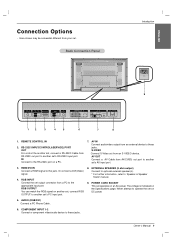
...Connection Options - Back Connection Panel Introduction AC IN 9 REMOTE CONTROL IN RS-232C (CONTROL&SERVICE) HDMI/DVI IN OUT IN RGB IN OUT AUDIO (RGB/DVI) COMPONENT IN VIDEO L-AUDIO-R 1 2 AV IN VIDEO L-AUDIO-R S-VIDEO AV OUT EXTERNAL SPEAKER R L 1 2 3 4 5 6 7 8 1. AV IN Connect audio/video output from RS-232C out port to this jack. S-VIDEO Connect S-Video out from your set 's RS-232C input port. AV OUT Connect a AV Cable from a PC to another set . Or connect a DVI(Video) signal. 4. RGB INPUT Connect the set operates on the Specifications page. POWER CORD...
...Connection Options - Back Connection Panel Introduction AC IN 9 REMOTE CONTROL IN RS-232C (CONTROL&SERVICE) HDMI/DVI IN OUT IN RGB IN OUT AUDIO (RGB/DVI) COMPONENT IN VIDEO L-AUDIO-R 1 2 AV IN VIDEO L-AUDIO-R S-VIDEO AV OUT EXTERNAL SPEAKER R L 1 2 3 4 5 6 7 8 1. AV IN Connect audio/video output from RS-232C out port to this jack. S-VIDEO Connect S-Video out from your set 's RS-232C input port. AV OUT Connect a AV Cable from a PC to another set . Or connect a DVI(Video) signal. 4. RGB INPUT Connect the set operates on the Specifications page. POWER CORD...
Owners Manual
Page 10
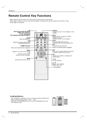
... the remote IR signal is supported. AUTO Automatic adjustment function. (Operational for the analog signal only) ARC Changes the picture format. Selects menu item. * : No function Installing Batteries • Open the battery compartment cover on screen menus one by one. PSM Adjusts the factory preset picture according to monitor viewing from any menu. Memorizes menu changes. switches the set on or off to AV Component1 Component2 RGB HDMI/DVI. Under certain conditions such as necessary. SLEEP Sets the sleep timer...
... the remote IR signal is supported. AUTO Automatic adjustment function. (Operational for the analog signal only) ARC Changes the picture format. Selects menu item. * : No function Installing Batteries • Open the battery compartment cover on screen menus one by one. PSM Adjusts the factory preset picture according to monitor viewing from any menu. Memorizes menu changes. switches the set on or off to AV Component1 Component2 RGB HDMI/DVI. Under certain conditions such as necessary. SLEEP Sets the sleep timer...
Owners Manual
Page 11
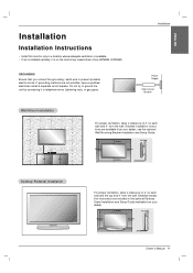
... from your dealer. 4 inches 4 inches 4 inches 4 inches Owner's Manual 11 Detailed installation instructions are included in a location where adequate ventilation is available. • If set is on each side and 4" from the wall. ENGLISH Installation Installation Instructions • Install this monitor only in the optional Desktop Stand Installation and Setup Guide available from your dealer, see the optional Wall Mounting Bracket Installation and Setup Guide. 4 inches 4 inches 4 inches 4 inches 4 inches Desktop Pedestal Installation For proper ventilation, allow...
... from your dealer. 4 inches 4 inches 4 inches 4 inches Owner's Manual 11 Detailed installation instructions are included in a location where adequate ventilation is available. • If set is on each side and 4" from the wall. ENGLISH Installation Installation Instructions • Install this monitor only in the optional Desktop Stand Installation and Setup Guide available from your dealer, see the optional Wall Mounting Bracket Installation and Setup Guide. 4 inches 4 inches 4 inches 4 inches 4 inches Desktop Pedestal Installation For proper ventilation, allow...
Owners Manual
Page 12
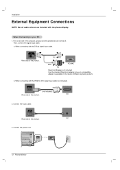
... display. HDMI/DVI IN (not included) Rear side of the product. Installation External Equipment Connections NOTE: Not all , see if the computer, product and the peripherals are included with the D-Sub signal input cable. PC MAC PC/MAC Macintosh Adapter (not included) Use the standard Macintosh adapter since an incompatible adapter is available in the market. (Different signaling system) b. AUDIO (RGB/DVI) Rear side of the product. Connect the power cord. a. Connect...
... display. HDMI/DVI IN (not included) Rear side of the product. Installation External Equipment Connections NOTE: Not all , see if the computer, product and the peripherals are included with the D-Sub signal input cable. PC MAC PC/MAC Macintosh Adapter (not included) Use the standard Macintosh adapter since an incompatible adapter is available in the market. (Different signaling system) b. AUDIO (RGB/DVI) Rear side of the product. Connect the power cord. a. Connect...
Owners Manual
Page 13
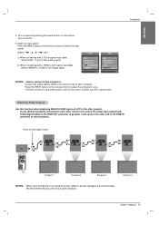
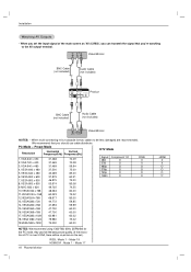
... Use this function when displaying ANALOG RGB inputs of a PC to the other products. 15-pin D-Sub Signal Cable RGB IN OUT RGB IN OUT RGB IN OUT RGB IN OUT PC Product 1 Product 2 Product 3 Product 4 NOTES: • When multi-connecting in/out cascade format, cables to be less damaged are recommended. Owner's Manual 13 Turn on power by pressing the power button on the remote control to DVI Digital signal. When connecting with a HDMI to DVI signal input cable...
... Use this function when displaying ANALOG RGB inputs of a PC to the other products. 15-pin D-Sub Signal Cable RGB IN OUT RGB IN OUT RGB IN OUT RGB IN OUT PC Product 1 Product 2 Product 3 Product 4 NOTES: • When multi-connecting in/out cascade format, cables to be less damaged are recommended. Owner's Manual 13 Turn on power by pressing the power button on the remote control to DVI Digital signal. When connecting with a HDMI to DVI signal input cable...
Owners Manual
Page 14
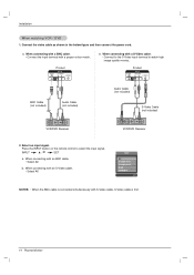
...) BNC Cable (not included) Audio Cable (not included) S-Video Cable (not included) VCR/DVD Receiver VCR/DVD Receiver 2. Press the INPUT button on the remote control to watch high image quality movies. When connecting with a proper colour match. When connecting with a BNC cable. • Connect the input terminal with an S-Video cable. • Select AV. Select an input signal. When connecting with S-Video cable, S-Video cable is first. 14 Plasma Monitor Input AV Component1 Component2 RGB HDMI/DVI NOTES...
...) BNC Cable (not included) Audio Cable (not included) S-Video Cable (not included) VCR/DVD Receiver VCR/DVD Receiver 2. Press the INPUT button on the remote control to watch high image quality movies. When connecting with a proper colour match. When connecting with a BNC cable. • Connect the input terminal with an S-Video cable. • Select AV. Select an input signal. When connecting with S-Video cable, S-Video cable is first. 14 Plasma Monitor Input AV Component1 Component2 RGB HDMI/DVI NOTES...
Owners Manual
Page 15
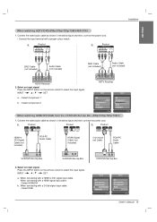
... cord. • Connect the input terminal with a D-Sub signal input cable. • Select RGB VCR/DVD/Set-top Box Input AV Component1 Component2 RGB HDMI/DVI Input AV Component1 Component2 RGB HDMI/DVI Owner's Manual 15 Product HDMI/DVI IN RGB IN OUT AUDIO (RGB/DVI) Product HDMI/DVI IN RGB IN OUT AUDIO (RGB/DVI) b. Connect the video/audio cable as shown in the below figure and then connect the power cord. When connecting with a proper colour match. a. Select an input signal. Press the INPUT button on the remote control to select the input signal. INPUT...
... cord. • Connect the input terminal with a D-Sub signal input cable. • Select RGB VCR/DVD/Set-top Box Input AV Component1 Component2 RGB HDMI/DVI Input AV Component1 Component2 RGB HDMI/DVI Owner's Manual 15 Product HDMI/DVI IN RGB IN OUT AUDIO (RGB/DVI) Product HDMI/DVI IN RGB IN OUT AUDIO (RGB/DVI) b. Connect the video/audio cable as shown in the below figure and then connect the power cord. When connecting with a proper colour match. a. Select an input signal. Press the INPUT button on the remote control to select the input signal. INPUT...
Owners Manual
Page 16
Preset Mode Resolution Horizontal Vertical Frequency(kHz) Frequency(Hz) 1. VGA 640 x 480 31.468 31.469 31.469 70.09 70.08 59.94 DTV Mode Signal 480i 576i 480p Component 1/2 O O O RGB X X O 4. We recommend that you're watching to be no picture on the set the input signal of the main screen as 'AV (CVBS)', you can transmit the signal that you set .) RGB : Mode 1 ~ Mode 19 HDMI/DVI : Mode 1 ~ Mode 17 16 Plasma Monitor HDMI X X O O O O VGA 640...
Preset Mode Resolution Horizontal Vertical Frequency(kHz) Frequency(Hz) 1. VGA 640 x 480 31.468 31.469 31.469 70.09 70.08 59.94 DTV Mode Signal 480i 576i 480p Component 1/2 O O O RGB X X O 4. We recommend that you're watching to be no picture on the set the input signal of the main screen as 'AV (CVBS)', you can transmit the signal that you set .) RGB : Mode 1 ~ Mode 19 HDMI/DVI : Mode 1 ~ Mode 17 16 Plasma Monitor HDMI X X O O O O VGA 640...

Owners Manual
Page 17
... the language of your choice. 4. Press the INPUT or button on the Monitor or press the POWER, INPUT button on the screen in this manual. At this point on, the on-screen menus will switch on the Monitor just after installation 1. ENGLISH Operation Your Monitor's OSD (On Screen Display) may differ slightly from what is switched to standby mode. 2. Connect power cord correctly. Press the G button and then use D / E button to the previous menu. Turning on the Monitor Turning on...
... the language of your choice. 4. Press the INPUT or button on the Monitor or press the POWER, INPUT button on the screen in this manual. At this point on, the on-screen menus will switch on the Monitor just after installation 1. ENGLISH Operation Your Monitor's OSD (On Screen Display) may differ slightly from what is switched to standby mode. 2. Connect power cord correctly. Press the G button and then use D / E button to the previous menu. Turning on the Monitor Turning on...
Owners Manual
Page 19
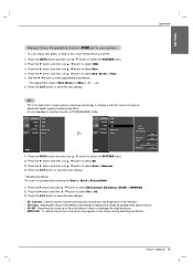
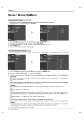
... the screen during watching the Monitor. Press the G button and then D / E button to select On or Off. 3. ENGLISH Operation Manual Colour Temperature Control (CSM set to any colour temperature you prefer. 1. Press the MENU button and then use this function in PC[RGB/HDMI] mode. You can adjust red, green, or blue to user option) - Press the G button and then use D / E button to select Red, Green or Blue. 5. PICTURE G PSM SOUND0 CSM TIME0 SPECIAL0 SCREEN0 Advanced Reset...
... the screen during watching the Monitor. Press the G button and then D / E button to select On or Off. 3. ENGLISH Operation Manual Colour Temperature Control (CSM set to any colour temperature you prefer. 1. Press the MENU button and then use this function in PC[RGB/HDMI] mode. You can adjust red, green, or blue to user option) - Press the G button and then use D / E button to select Red, Green or Blue. 5. PICTURE G PSM SOUND0 CSM TIME0 SPECIAL0 SCREEN0 Advanced Reset...

Owners Manual
Page 25
... use D / E button to select the SPECIAL menu. 2. Press the G button and then use D / E button to turn the monitor on the screen. Menu Prev. However, it was last set this to remain on . / I, INPUT ISM (Image Sticking Minimization) Method - Menu Prev. 1. set to even if you turn the monitor off with the remote control. - To return to normal viewing, press the any fixed image to Normal. • White wash White Wash removes permanent images from a PC/video game displayed...
... use D / E button to select the SPECIAL menu. 2. Press the G button and then use D / E button to turn the monitor on the screen. Menu Prev. However, it was last set this to remain on . / I, INPUT ISM (Image Sticking Minimization) Method - Menu Prev. 1. set to even if you turn the monitor off with the remote control. - To return to normal viewing, press the any fixed image to Normal. • White wash White Wash removes permanent images from a PC/video game displayed...
Owners Manual
Page 30
... the wide screen signal, it will lead you to adjust the picture horizontally or vertically, in a linear proportion, to fill the entire screen fully. (Europe an version only) • Original When your AV receives the wide screen signal, it will be lost. 4. Manual config. PICTURE0 SOUND0 TIME0 SPECIAL0 SCREEN0 Auto config. XGA Mode ARC Reset Menu Prev. Press the G button and then use D / E button to save the new settings. 30 Plasma Monitor...
... the wide screen signal, it will lead you to adjust the picture horizontally or vertically, in a linear proportion, to fill the entire screen fully. (Europe an version only) • Original When your AV receives the wide screen signal, it will be lost. 4. Manual config. PICTURE0 SOUND0 TIME0 SPECIAL0 SCREEN0 Auto config. XGA Mode ARC Reset Menu Prev. Press the G button and then use D / E button to save the new settings. 30 Plasma Monitor...
Owners Manual
Page 32
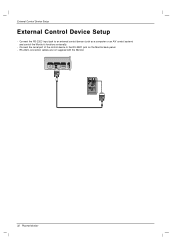
Connect the serial port of the control device to an external control device (such as a computer or an A/V control system) and control the Monitor's functions externally. - RS-232C connection cables are not supplied with the Monitor. Connect the RS-232C input jack to the RS-232C jack on the Monitor back panel. - External Control Device Setup External Control Device Setup - REMOTE CONTROL IN RS-232C (CONTROL&SERVICE) OUT IN HDMI/DVI IN RGB OUT IN AUDIO (RGB/DVI) COMPONENT IN VIDEO L-AUDIO-R 1 2 VIDEO AV...
Connect the serial port of the control device to an external control device (such as a computer or an A/V control system) and control the Monitor's functions externally. - RS-232C connection cables are not supplied with the Monitor. Connect the RS-232C input jack to the RS-232C jack on the Monitor back panel. - External Control Device Setup External Control Device Setup - REMOTE CONTROL IN RS-232C (CONTROL&SERVICE) OUT IN HDMI/DVI IN RGB OUT IN AUDIO (RGB/DVI) COMPONENT IN VIDEO L-AUDIO-R 1 2 VIDEO AV...
Owners Manual
Page 33
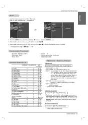
... SPECIAL menu. 2. Press the G button and then use the D / E button to specify a monitor ID number. - Remote Lock /Key Lock k 14. Set ID is data write mode, it returns NG Owner's Manual 33 Volume Control k 07. Tint k 11. Command Reference List COMMAND 1 COMMAND 2 DATA (Hexadecimal) 01. Input Select k 03. Press the G button and then use F / G button to adjust Set ID to read mode, it indicates present status data. Screen Mute k 05. Contrast k 08. ISM mode j 18. Use...
... SPECIAL menu. 2. Press the G button and then use the D / E button to specify a monitor ID number. - Remote Lock /Key Lock k 14. Set ID is data write mode, it returns NG Owner's Manual 33 Volume Control k 07. Tint k 11. Command Reference List COMMAND 1 COMMAND 2 DATA (Hexadecimal) 01. Input Select k 03. Press the G button and then use F / G button to adjust Set ID to read mode, it indicates present status data. Screen Mute k 05. Contrast k 08. ISM mode j 18. Use...
Owners Manual
Page 34
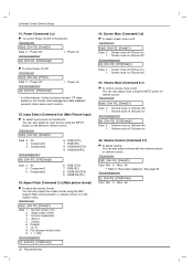
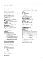
Power (Command 2:a) G To control Power On/Off of the Monitor. Acknowledgement [f][ ][Set ID][ ][OK][Data][x] Data Min : 0 ~ Max : 64 You can also adjust the screen format using the ARC (Aspect Ratio Control) button on remote control or in the Screen menu. Transmission [k][b][ ][Set ID][ ][Data][Cr] Data 2 : AV 4 : Component1 5 : Component2 Acknowledgement [b][ ][Set ID][ ][OK][Data][x] 6 : RGB (DTV) 7 : RGB (PC) 8 : HDMI/DVI(DTV) 9 : HDMI/DVI(PC) Data 2 : AV 4 : Component1 5 : Component2 6 : RGB (DTV) 7 : RGB (PC) 8 : HDMI/DVI(DTV) 9 : HDMI/DVI(PC...
Power (Command 2:a) G To control Power On/Off of the Monitor. Acknowledgement [f][ ][Set ID][ ][OK][Data][x] Data Min : 0 ~ Max : 64 You can also adjust the screen format using the ARC (Aspect Ratio Control) button on remote control or in the Screen menu. Transmission [k][b][ ][Set ID][ ][Data][Cr] Data 2 : AV 4 : Component1 5 : Component2 Acknowledgement [b][ ][Set ID][ ][OK][Data][x] 6 : RGB (DTV) 7 : RGB (PC) 8 : HDMI/DVI(DTV) 9 : HDMI/DVI(PC) Data 2 : AV 4 : Component1 5 : Component2 6 : RGB (DTV) 7 : RGB (PC) 8 : HDMI/DVI(DTV) 9 : HDMI/DVI(PC...
Owners Manual
Page 36
... 3: User 16. Abnormal state (Command2 : z) G Abnormal State : Used to Read the power off status when Stand-by auto off function Acknowledgement [z][ ][Set ID][ ][OK][Data][x] 17. Auto Configure (Command: j u) G To adjust picture position and minimize image shaking automatically. Acknowledgement [d][ ][Set ID][ ][OK][Data][x] Transmission [k][z][ ][Set ID][ ][Data][Cr] Data FF : Read 0 : Normal (Power on and signal exist) 1: No signal (Power on) 2 : Turn the monitor off by remote control 3 : Turn the monitor off by sleep...
... 3: User 16. Abnormal state (Command2 : z) G Abnormal State : Used to Read the power off status when Stand-by auto off function Acknowledgement [z][ ][Set ID][ ][OK][Data][x] 17. Auto Configure (Command: j u) G To adjust picture position and minimize image shaking automatically. Acknowledgement [d][ ][Set ID][ ][OK][Data][x] Transmission [k][z][ ][Set ID][ ][Data][Cr] Data FF : Read 0 : Normal (Power on and signal exist) 1: No signal (Power on) 2 : Turn the monitor off by remote control 3 : Turn the monitor off by sleep...
Owners Manual
Page 40
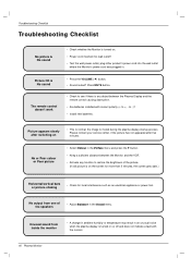
... . • Power cord inserted into wall outlet? • Test the wall power outlet, plug other product's power cord into the wall outlet where the Monitor's power cord was plugged in the Sound menu. Picture OK & No sound The remote control doesn't work • Press the VOLUME ( G) button. • Sound muted? No or Poor colour or Poor picture • Select Colour in the Picture menu and press the G button. • Keep a sufficient distance between the Plasma Display and the remote control causing...
... . • Power cord inserted into wall outlet? • Test the wall power outlet, plug other product's power cord into the wall outlet where the Monitor's power cord was plugged in the Sound menu. Picture OK & No sound The remote control doesn't work • Press the VOLUME ( G) button. • Sound muted? No or Poor colour or Poor picture • Select Colour in the Picture menu and press the G button. • Keep a sufficient distance between the Plasma Display and the remote control causing...


