Owners Manual
Page 2
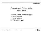
Troubleshooting Overview of Topics to be Discussed •Switch Mode Power Supply •Y SUS Board •Z SUS Board •X Drive Boards Plasma Display Panel Troubleshooting - 2007 2
Troubleshooting Overview of Topics to be Discussed •Switch Mode Power Supply •Y SUS Board •Z SUS Board •X Drive Boards Plasma Display Panel Troubleshooting - 2007 2

Owners Manual
Page 6
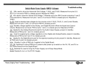
... Q702 closing the Relays RL101 and RL102 turning on the 3.3V, 5V, 6V, 12V, and 19V supplies. • VS-ON applied from the Power Board Pin1 of the Standby Voltages and the VA, VS, and 5v DC, set in and turned off. Guide Plus not programmed or Cable Card not... Plus has been programmed the set is plugged in full operation. SMPS outputting all of P800 to the Power Board on 5V-DC. • 5V-D is powered off for TVGOS Data. • Standby Operation - The SMPS outputs S 5v (Standby). Plasma Display Panel Troubleshooting - 2007 6 Standby 5v • AC Detect sent from the Digital...
... Q702 closing the Relays RL101 and RL102 turning on the 3.3V, 5V, 6V, 12V, and 19V supplies. • VS-ON applied from the Power Board Pin1 of the Standby Voltages and the VA, VS, and 5v DC, set in and turned off. Guide Plus not programmed or Cable Card not... Plus has been programmed the set is plugged in full operation. SMPS outputting all of P800 to the Power Board on 5V-DC. • 5V-D is powered off for TVGOS Data. • Standby Operation - The SMPS outputs S 5v (Standby). Plasma Display Panel Troubleshooting - 2007 6 Standby 5v • AC Detect sent from the Digital...
Owners Manual
Page 7
...to chassis ground. • 6v Applied to the Digital Board used for the circuits on the 5V-DC Supply. Plasma Display Panel Troubleshooting - 2007 7 Switch Mode Power Supply (SMPS) Voltages Troubleshooting • VS 196v used to bring the Power Supply out of Deep Sleep Mode. • 5V-M ...Needed to turn on the Y SUS, Z SUS, X, and Control Boards. Measured from pins 8, 9,...
...to chassis ground. • 6v Applied to the Digital Board used for the circuits on the 5V-DC Supply. Plasma Display Panel Troubleshooting - 2007 7 Switch Mode Power Supply (SMPS) Voltages Troubleshooting • VS 196v used to bring the Power Supply out of Deep Sleep Mode. • 5V-M ...Needed to turn on the Y SUS, Z SUS, X, and Control Boards. Measured from pins 8, 9,...
Owners Manual
Page 22
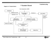
Diagram of Y Sustain Board Y Sustain Board Z SUS Board Distributes 5v VA VS Distributes 5v VA Power Supply Board - SMPS Receive 5V,Va, Vs from SMPS Distributes 5v IPM generates Sustain Waveform Generates Vsc, -Vy from 5v VA Vs by transformer. Bottom Left X Board FETs amplify Sustain Waveform Troubleshooting Control Board Logic signals needed to generate drive waveform Transfer Waveform to Y Drive Board Display Panel Plasma Display Panel Troubleshooting - 2007 22
Diagram of Y Sustain Board Y Sustain Board Z SUS Board Distributes 5v VA VS Distributes 5v VA Power Supply Board - SMPS Receive 5V,Va, Vs from SMPS Distributes 5v IPM generates Sustain Waveform Generates Vsc, -Vy from 5v VA Vs by transformer. Bottom Left X Board FETs amplify Sustain Waveform Troubleshooting Control Board Logic signals needed to generate drive waveform Transfer Waveform to Y Drive Board Display Panel Plasma Display Panel Troubleshooting - 2007 22
Owners Manual
Page 23
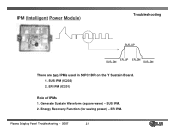
Generate Sustain Waveform (square wave) - Plasma Display Panel Troubleshooting - 2007 23 ER IPM. SUS IPM (IC202) 2. SUS IPM. 2. ER IPM (IC201) Role of IPMs 1. IPM (Intelligent Power Module) Troubleshooting SUS_UP ER_UP ER_DN SUS_DN SUS_DN There are two IPMs used in 50PC1DR on the Y Sustain Board. 1. Energy Recovery Function (for saving power) -
Generate Sustain Waveform (square wave) - Plasma Display Panel Troubleshooting - 2007 23 ER IPM. SUS IPM (IC202) 2. SUS IPM. 2. ER IPM (IC201) Role of IPMs 1. IPM (Intelligent Power Module) Troubleshooting SUS_UP ER_UP ER_DN SUS_DN SUS_DN There are two IPMs used in 50PC1DR on the Y Sustain Board. 1. Energy Recovery Function (for saving power) -
Owners Manual
Page 29
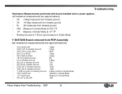
Troubleshooting Resistance Measurements performed with board installed and no power applied (all resistance measurements are approximations) • VA 3 Meg measured from chassis ground • VS...• -VY Measure in Diode Mode at -VY TP • Floating Ground to Y Drive input measure in Diode Mode Y SUSTAIN Board removed from PDP Assembly (all resistance measurements are approximations) • VS to SUS OUT 1 Meg • SUS OUT to Chassis Ground...in Diode Mode • -VY Test Points Measure in Diode Mode • ER_UP to ER_DN 20K Plasma Display Panel Troubleshooting - 2007 29
Troubleshooting Resistance Measurements performed with board installed and no power applied (all resistance measurements are approximations) • VA 3 Meg measured from chassis ground • VS...• -VY Measure in Diode Mode at -VY TP • Floating Ground to Y Drive input measure in Diode Mode Y SUSTAIN Board removed from PDP Assembly (all resistance measurements are approximations) • VS to SUS OUT 1 Meg • SUS OUT to Chassis Ground...in Diode Mode • -VY Test Points Measure in Diode Mode • ER_UP to ER_DN 20K Plasma Display Panel Troubleshooting - 2007 29
Owners Manual
Page 41
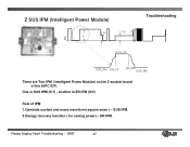
ER IPM. SUS IPM. 2.Energy recovery function ( for saving power) - Z SUS IPM (Intelligent Power Module) 95 V Z Vs 95V Vs SUS_UP Troubleshooting SUS_DN ER_UP ER_DN SUS_DN There are Two IPM ( Intelligent Power Module) on the Z sustain board of the 50PC1DR. One is SUS IPM (IC7) , another is ER IPM (IC5) Role of IPM 1.Generate sustain and erase waveform( square wave ) - Plasma Display Panel Troubleshooting - 2007 41
ER IPM. SUS IPM. 2.Energy recovery function ( for saving power) - Z SUS IPM (Intelligent Power Module) 95 V Z Vs 95V Vs SUS_UP Troubleshooting SUS_DN ER_UP ER_DN SUS_DN There are Two IPM ( Intelligent Power Module) on the Z sustain board of the 50PC1DR. One is SUS IPM (IC7) , another is ER IPM (IC5) Role of IPM 1.Generate sustain and erase waveform( square wave ) - Plasma Display Panel Troubleshooting - 2007 41
Owners Manual
Page 45
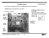
Power : 3.3V/5V Temperature diode Voltage Regulator Flash ROM Voltage Regulator Temperature display diode can be checked. In charge of all signal process and creating ON/OFF order of all FET on DRIVER B/D by receiving 8 bit R, G, B input. ◆. CONTROL Board Troubleshooting ◆. Left picture shows 7 periods which means normal temperature Green = OFF Yellow = ON Weight D15 - 8 D16 - 4 D17 - 2 D18 - 1 TEST Pattern AUTOGEN P1 Connector MCM (Micro Control Module) Plasma Display Panel Troubleshooting - 2007 LG Part Number Label 45
Power : 3.3V/5V Temperature diode Voltage Regulator Flash ROM Voltage Regulator Temperature display diode can be checked. In charge of all signal process and creating ON/OFF order of all FET on DRIVER B/D by receiving 8 bit R, G, B input. ◆. CONTROL Board Troubleshooting ◆. Left picture shows 7 periods which means normal temperature Green = OFF Yellow = ON Weight D15 - 8 D16 - 4 D17 - 2 D18 - 1 TEST Pattern AUTOGEN P1 Connector MCM (Micro Control Module) Plasma Display Panel Troubleshooting - 2007 LG Part Number Label 45


