Owners Manual
Page 3
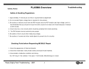
...Plasma Display Panel Troubleshooting - 2007 3 Do not exceed Higher voltage than is required for at least one minute because of residual current stored. 4. Check the appearance of defective condition and history. Check the model label. Check details of Panel and boards. 2. Be cautious of short circuit when measuring voltage. 7. Circuit drive has c-mos circuits... which should not touch the drive circuits for the product. 3. Ex) COF long 2-1 fail, ...
...Plasma Display Panel Troubleshooting - 2007 3 Do not exceed Higher voltage than is required for at least one minute because of residual current stored. 4. Check the appearance of defective condition and history. Check the model label. Check details of Panel and boards. 2. Be cautious of short circuit when measuring voltage. 7. Circuit drive has c-mos circuits... which should not touch the drive circuits for the product. 3. Ex) COF long 2-1 fail, ...

Owners Manual
Page 4
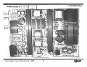
... the section the technician will have a better understanding of the operation of the PDP for the correct voltage levels for the Single Scan Plasma. V SET_UP -VY VSC Z_BIAS Plasma Display Panel Troubleshooting - 2007 4 Switch Mode Power Supply Troubleshooting This Section of the Presentation will cover troubleshooting the Switch Mode Power Supply for... the SMPS • Adjustments VA, VS, and 5V DC • Always refer to the sticker located in the upper right side of the Power Supply circuit and will vary from Panel to Panel.
... the section the technician will have a better understanding of the operation of the PDP for the correct voltage levels for the Single Scan Plasma. V SET_UP -VY VSC Z_BIAS Plasma Display Panel Troubleshooting - 2007 4 Switch Mode Power Supply Troubleshooting This Section of the Presentation will cover troubleshooting the Switch Mode Power Supply for... the SMPS • Adjustments VA, VS, and 5V DC • Always refer to the sticker located in the upper right side of the Power Supply circuit and will vary from Panel to Panel.
Owners Manual
Page 5
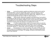
... supplies will sometimes leak dielectric material and give off a distinct odor. Be careful of ESD and make a final determination of the failure. Plasma Display Panel Troubleshooting - 2007 5 Look for burned parts and check for the proper Duty Cycle of the signals. If the supplies are noise... free. Troubleshooting Steps • Define Look at the symptom carefully and determine what circuits could be an indication of an eminent failure. • Correct The final step is to correct the problem. Look for correct Amplitude ...
... supplies will sometimes leak dielectric material and give off a distinct odor. Be careful of ESD and make a final determination of the failure. Plasma Display Panel Troubleshooting - 2007 5 Look for burned parts and check for the proper Duty Cycle of the signals. If the supplies are noise... free. Troubleshooting Steps • Define Look at the symptom carefully and determine what circuits could be an indication of an eminent failure. • Correct The final step is to correct the problem. Look for correct Amplitude ...
Owners Manual
Page 7
...and 10 of connector P804 to chassis ground. Adjusted at VR901 • 5v.DC Used to the Analog Board and used for the circuits on the 5V-DC Supply. Plasma Display Panel Troubleshooting - 2007 7 Adjusted at VR221. • 19v Applied to develop bias voltages for the Audio Output Supply, present ... from pins 1 and 2 of Deep Sleep Mode. • 5V-M Needed to chassis ground. • 12v Used for the signal processing circuits present in the IPM Circuits to develop Y and Z Drive waveforms. Measured from the Digital Board. • 5v-D Switched 5v used to bring the Power Supply out ...
...and 10 of connector P804 to chassis ground. Adjusted at VR901 • 5v.DC Used to the Analog Board and used for the circuits on the 5V-DC Supply. Plasma Display Panel Troubleshooting - 2007 7 Adjusted at VR221. • 19v Applied to develop bias voltages for the Audio Output Supply, present ... from pins 1 and 2 of Deep Sleep Mode. • 5V-M Needed to chassis ground. • 12v Used for the signal processing circuits present in the IPM Circuits to develop Y and Z Drive waveforms. Measured from the Digital Board. • 5v-D Switched 5v used to bring the Power Supply out ...
Owners Manual
Page 8
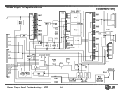
Power Supply VS Adjust VA Adjust VS VA Source VA 5v VS Source Control IC 3.3v Adjust 19v Audio Supply 12V,6V, 5V and 3.3V Source Standby Circuit P802 P803 P800 Plasma Display Panel Troubleshooting - 2007 8 Troubleshooting 380 Volt Supply AC Input Circuit
Power Supply VS Adjust VA Adjust VS VA Source VA 5v VS Source Control IC 3.3v Adjust 19v Audio Supply 12V,6V, 5V and 3.3V Source Standby Circuit P802 P803 P800 Plasma Display Panel Troubleshooting - 2007 8 Troubleshooting 380 Volt Supply AC Input Circuit
Owners Manual
Page 10
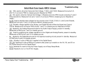
... Troubleshooting D951 VS D952 D953 D271 6V D261 Q252 D251 D202 VA 5V-M Q281 5V HS6 U261 Q223 D221 3.3v AC Input F101 AC INPUT Circuit Plasma Display Panel Troubleshooting - 2007 10
... Troubleshooting D951 VS D952 D953 D271 6V D261 Q252 D251 D202 VA 5V-M Q281 5V HS6 U261 Q223 D221 3.3v AC Input F101 AC INPUT Circuit Plasma Display Panel Troubleshooting - 2007 10
Owners Manual
Page 11
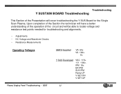
IPM 18v. ER IPM SUS IPM Ramp UP V SET DN V SET UP Plasma Display Panel Troubleshooting - 2007 11 Y SUS Developed VSC 115v. -VY -196v. VS 196v. 5v. Upon completion of the Section the technician will have a better ... of the operation of the Presentation will be able to locate voltage and resistance test points needed for the Single Scan Plasma. Troubleshooting Y SUSTAIN BOARD Troubleshooting This Section of the circuit and will cover troubleshooting the Y SUS Board for troubleshooting and alignments. • Adjustments • DC Voltage and Waveform Checks • ...
IPM 18v. ER IPM SUS IPM Ramp UP V SET DN V SET UP Plasma Display Panel Troubleshooting - 2007 11 Y SUS Developed VSC 115v. -VY -196v. VS 196v. 5v. Upon completion of the Section the technician will have a better ... of the operation of the Presentation will be able to locate voltage and resistance test points needed for the Single Scan Plasma. Troubleshooting Y SUSTAIN BOARD Troubleshooting This Section of the circuit and will cover troubleshooting the Y SUS Board for troubleshooting and alignments. • Adjustments • DC Voltage and Waveform Checks • ...
Owners Manual
Page 33
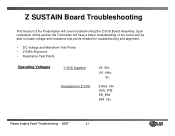
Z Bias 90v SUS_IPM ER_IPM IPM 18v Plasma Display Panel Troubleshooting - 2007 33 VS 196v. 5v. Upon completion of the circuit and be able to locate voltage and resistance test points needed for troubleshooting and alignment. • DC Voltage and Waveform Test Points • Z BIAS Alignment • Resistance Test Points Operating Voltages Y SUS Supplied Developed on Z SUS VA 60v. Z SUSTAIN Board Troubleshooting This Section of the Presentation will have a better understanding of this section the Technician will cover troubleshooting the Z-SUS Board Assembly.
Z Bias 90v SUS_IPM ER_IPM IPM 18v Plasma Display Panel Troubleshooting - 2007 33 VS 196v. 5v. Upon completion of the circuit and be able to locate voltage and resistance test points needed for troubleshooting and alignment. • DC Voltage and Waveform Test Points • Z BIAS Alignment • Resistance Test Points Operating Voltages Y SUS Supplied Developed on Z SUS VA 60v. Z SUSTAIN Board Troubleshooting This Section of the Presentation will have a better understanding of this section the Technician will cover troubleshooting the Z-SUS Board Assembly.
Owners Manual
Page 34
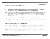
... routed to connectors P152 and P153 at right side of P151 to chassis ground. 5v Used to Bias the circuits on the Z SUS Board Z Bias 90v used to Bias the output circuits that drive the Sustain and Erase pulses for the PDP. Input measured from pins 8 and 9 of resistor R100... and to generate the Sustain and Erase pulses in the IPMs. Measured at pin 7 of the Z Bias Circuit. IPM 18v Needed to the Primary Winding of Transformer T2 of each connector. Plasma Display Panel Troubleshooting - 2007 34 VA Supplied to the Center and Bottom Right X Boards. Measured across parallel ...
... routed to connectors P152 and P153 at right side of P151 to chassis ground. 5v Used to Bias the circuits on the Z SUS Board Z Bias 90v used to Bias the output circuits that drive the Sustain and Erase pulses for the PDP. Input measured from pins 8 and 9 of resistor R100... and to generate the Sustain and Erase pulses in the IPMs. Measured at pin 7 of the Z Bias Circuit. IPM 18v Needed to the Primary Winding of Transformer T2 of each connector. Plasma Display Panel Troubleshooting - 2007 34 VA Supplied to the Center and Bottom Right X Boards. Measured across parallel ...
Owners Manual
Page 43
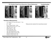
... 10K • ER_DN to remove Pull FPC Connector as shown in circles Pull Lock apart to Chassis Ground 10K *Measurements made with the board disconnected Plasma Display Panel Troubleshooting - 2007 43 FPC (Flexible Printed Circuit) Removal for Z Board Replacement Troubleshooting Pull out Lock as shown in arrow.
... 10K • ER_DN to remove Pull FPC Connector as shown in circles Pull Lock apart to Chassis Ground 10K *Measurements made with the board disconnected Plasma Display Panel Troubleshooting - 2007 43 FPC (Flexible Printed Circuit) Removal for Z Board Replacement Troubleshooting Pull out Lock as shown in arrow.
Owners Manual
Page 58
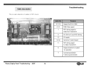
Purpose 8 9 10 2 3 4 1 Supply Va,5V to X B/D RGB Video signal FET driving signal to make the Y waveform 5 13 14 12 11 5V,15V for IC and FET driving 5V supply Va,Vs for Y and Z board FET driving signal to make Z waveform 6 Supply waveform on panel for operation 7 Connecting between Y drive top and bottom Plasma Display Panel Troubleshooting - 2007 58 Cable description This is total collection of cables in PDP circuit , Troubleshooting ⑥ ⑦ ⑧ ⑫ ⑭ ⑬ ⑤ ⑪ ⑨⑩ Cable No.
Purpose 8 9 10 2 3 4 1 Supply Va,5V to X B/D RGB Video signal FET driving signal to make the Y waveform 5 13 14 12 11 5V,15V for IC and FET driving 5V supply Va,Vs for Y and Z board FET driving signal to make Z waveform 6 Supply waveform on panel for operation 7 Connecting between Y drive top and bottom Plasma Display Panel Troubleshooting - 2007 58 Cable description This is total collection of cables in PDP circuit , Troubleshooting ⑥ ⑦ ⑧ ⑫ ⑭ ⑬ ⑤ ⑪ ⑨⑩ Cable No.
Owners Manual
Page 60
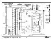
... L4 D9 L2 VSET GND D11 R88 R100 V SET UP L7 VSET UP TP ER_I0 VS_2 ER_ LOW ER_UP ER_DN -VY IC303 IC302 VSET DN Circuits HS4 PS1 VS IC2 15v SUS_ OUT GND ER_ HIGH SUS_UP SUS_DN ER_l0 VS_2 ER_ LOW 5v ER_UP ER_DN P7 GND 5V VA Logic signals...
... L4 D9 L2 VSET GND D11 R88 R100 V SET UP L7 VSET UP TP ER_I0 VS_2 ER_ LOW ER_UP ER_DN -VY IC303 IC302 VSET DN Circuits HS4 PS1 VS IC2 15v SUS_ OUT GND ER_ HIGH SUS_UP SUS_DN ER_l0 VS_2 ER_ LOW 5v ER_UP ER_DN P7 GND 5V VA Logic signals...
