Owners Manual
Page 6
... 20 DVD Setup 23 VCR Setup 25 Other A/V Source Setup 27 USB Connection 28 Audio out Connection 29 PC Setup 30 WATCHING TV / CHANNEL CONTROL Remote Control Functions 36 Turning On TV 38 Channel Selection 38 Volume Adjustment 38 Initial Setting 39 On-Screen Menus Selection 40 Quick Menu 41 6 Channel Setup - Add / Delete...
... 20 DVD Setup 23 VCR Setup 25 Other A/V Source Setup 27 USB Connection 28 Audio out Connection 29 PC Setup 30 WATCHING TV / CHANNEL CONTROL Remote Control Functions 36 Turning On TV 38 Channel Selection 38 Volume Adjustment 38 Initial Setting 39 On-Screen Menus Selection 40 Quick Menu 41 6 Channel Setup - Add / Delete...
Owners Manual
Page 7
... User Mode 79 Balance 80 Audio Reset 81 TV Speakers On/Off Setup 82 External Speakers On/Off Setup 83 Stereo/SAP Broadcasts Setup 84 Audio Language 85 On-Screen Menus Language Selection 86 Caption Mode - SOUND & LANGUAGE CONTROL Auto Volume Leveler (Auto Volume 76 Clear Voice...Clock Setup 90 Manual Clock Setup 91 Auto On/Off Time Setting 92 Sleep Timer Setting 93 PARENTAL CONTROL / RATINGS Set Password & Lock System 94 Channel Blocking 97 Movie & TV Rating 98 Downloadable Rating 101 External Input Blocking 102 Key Lock 103 APPENDIX Troubleshooting 104 Maintenance 106 ...
... User Mode 79 Balance 80 Audio Reset 81 TV Speakers On/Off Setup 82 External Speakers On/Off Setup 83 Stereo/SAP Broadcasts Setup 84 Audio Language 85 On-Screen Menus Language Selection 86 Caption Mode - SOUND & LANGUAGE CONTROL Auto Volume Leveler (Auto Volume 76 Clear Voice...Clock Setup 90 Manual Clock Setup 91 Auto On/Off Time Setting 92 Sleep Timer Setting 93 PARENTAL CONTROL / RATINGS Set Password & Lock System 94 Channel Blocking 97 Movie & TV Rating 98 Downloadable Rating 101 External Input Blocking 102 Key Lock 103 APPENDIX Troubleshooting 104 Maintenance 106 ...
Owners Manual
Page 9
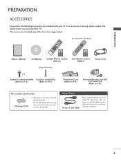
...Control, Batteries Batteries Power Cord (Except 47LH300C) x 4 Screws for stand assembly Screw for stand fixing (Refer to P.12) (Refer to P.17) Protection Cover (Refer to P.13) Protective Bracket and Bolt for Power Cord (Refer to maintain standards compliance. 9 Option Extras D-sub 15 pin Cable When using the VGA... (D-sub 15 pin cable) PC connection, the user must use shielded signal interface cables with your TV. PREPARATION PREPARATION ACCESSORIES Ensure that the following accessories are included with ...
...Control, Batteries Batteries Power Cord (Except 47LH300C) x 4 Screws for stand assembly Screw for stand fixing (Refer to P.12) (Refer to P.17) Protection Cover (Refer to P.13) Protective Bracket and Bolt for Power Cord (Refer to maintain standards compliance. 9 Option Extras D-sub 15 pin Cable When using the VGA... (D-sub 15 pin cable) PC connection, the user must use shielded signal interface cables with your TV. PREPARATION PREPARATION ACCESSORIES Ensure that the following accessories are included with ...
Owners Manual
Page 10
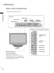
PREPARATION PREPARATION FRONT PANEL INFORMATION I Image shown may differ from your TV. 26LH210C INPUT Button POWER Button MENU Button ENTER Button VOLUME CHANNEL (-, +) Buttons (E,D) Buttons INPUT MENU ENTER VOL CH 32LH210C, 32/37/42LH200C, 47LH300C SPEAKER Remote Control Sensor, Power/Standby Indicator Illuminates red in the OPTION menu. Illuminates blue when the TV is switched on. (Can be adjusted using the Power Indicator in standby mode. G p.74) CH VOL ENTER MENU INPUT CHANNEL (D,E) Buttons VOLUME (+, -) Buttons ENTER Button MENU Button INPUT Button POWER Button 10
PREPARATION PREPARATION FRONT PANEL INFORMATION I Image shown may differ from your TV. 26LH210C INPUT Button POWER Button MENU Button ENTER Button VOLUME CHANNEL (-, +) Buttons (E,D) Buttons INPUT MENU ENTER VOL CH 32LH210C, 32/37/42LH200C, 47LH300C SPEAKER Remote Control Sensor, Power/Standby Indicator Illuminates red in the OPTION menu. Illuminates blue when the TV is switched on. (Can be adjusted using the Power Indicator in standby mode. G p.74) CH VOL ENTER MENU INPUT CHANNEL (D,E) Buttons VOLUME (+, -) Buttons ENTER Button MENU Button INPUT Button POWER Button 10
Owners Manual
Page 11
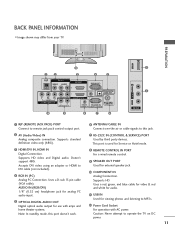
...with AC power. Supports standard definition video only (480i). 7 RS-232C IN (CONTROL & SERVICE) PORT Used by third party devices. Doesn't support 480i. BACK PANEL INFORMATION I Image shown may differ from your TV. This port is used for external speaker jack. 10 COMPONENT IN Analog Connection. ...VGA cable). Uses a red, green, and blue cable for video & red and white for audio. 11 USB IN Used for viewing photos and listening to this port doesn't work. 8 REMOTE CONTROL IN PORT For a wired remote control. 9 SPEAKER OUT PORT Used for Service or Hotel mode. 3 HDMI/DVI IN, HDMI ...
...with AC power. Supports standard definition video only (480i). 7 RS-232C IN (CONTROL & SERVICE) PORT Used by third party devices. Doesn't support 480i. BACK PANEL INFORMATION I Image shown may differ from your TV. This port is used for external speaker jack. 10 COMPONENT IN Analog Connection. ...VGA cable). Uses a red, green, and blue cable for video & red and white for audio. 11 USB IN Used for viewing photos and listening to this port doesn't work. 8 REMOTE CONTROL IN PORT For a wired remote control. 9 SPEAKER OUT PORT Used for Service or Hotel mode. 3 HDMI/DVI IN, HDMI ...
Owners Manual
Page 20
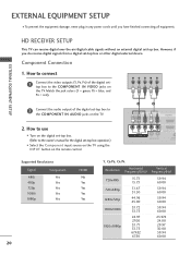
...However, if you have finished connecting all equipment. How to the COMPONENT IN AUDIO jacks on the TV. 2. EXTERNAL EQUIPMENT SETUP I Select the Component input source on the TV using the INPUT button on the remote control. 1 2 RJP AV IN 1 VIDEO AUDIO 2 L(MONO) R 1 VIDEO COMPONENT IN L ...AUDIO R L R SPEAKER OUT /DVI IN REMO CONTRO Supported Resolutions Signal Component 480i Yes 480p Yes 720p Yes 1080i Yes 1080p Yes HDMI No Yes ...
...However, if you have finished connecting all equipment. How to the COMPONENT IN AUDIO jacks on the TV. 2. EXTERNAL EQUIPMENT SETUP I Select the Component input source on the TV using the INPUT button on the remote control. 1 2 RJP AV IN 1 VIDEO AUDIO 2 L(MONO) R 1 VIDEO COMPONENT IN L ...AUDIO R L R SPEAKER OUT /DVI IN REMO CONTRO Supported Resolutions Signal Component 480i Yes 480p Yes 720p Yes 1080i Yes 1080p Yes HDMI No Yes ...
Owners Manual
Page 21
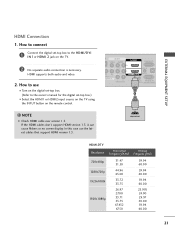
...L(MONO) R 1 DEO ONENT IN L AUDIO R L R SPEAKER OUT RGB IN (PC) AUDIO IN O /DVI IN (RGB/DVI) REMOTE RS-232C IN CONTROL IN (CONTROL&SERVICE) 1 HDMI OUTPUT HDMI-DTV Resolution Horizontal Vertical Frequency(KHz) Frequency(Hz) 720x480p 1280x720p 1920x1080i 1920x1080p 31.47 31.50 44.96 45.00 33.72 33.75... the digital set-top box to the owner's manual for the digital set -top box. (Refer to the HDMI/DVI I Select the HDMI1 or HDMI2 input source on the TV using the INPUT button on the TV. 2 No separate audio connection is necessary. HDMI supports both audio and video. 2.
...L(MONO) R 1 DEO ONENT IN L AUDIO R L R SPEAKER OUT RGB IN (PC) AUDIO IN O /DVI IN (RGB/DVI) REMOTE RS-232C IN CONTROL IN (CONTROL&SERVICE) 1 HDMI OUTPUT HDMI-DTV Resolution Horizontal Vertical Frequency(KHz) Frequency(Hz) 720x480p 1280x720p 1920x1080i 1920x1080p 31.47 31.50 44.96 45.00 33.72 33.75... the digital set-top box to the owner's manual for the digital set -top box. (Refer to the HDMI/DVI I Select the HDMI1 or HDMI2 input source on the TV using the INPUT button on the TV. 2 No separate audio connection is necessary. HDMI supports both audio and video. 2.
Owners Manual
Page 22
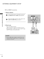
...the HDMI1 or HDMI2 input source on the TV using the INPUT button on the remote control. AV IN 1 O AUDIO 2 L(MONO) R 1 L AUDIO R L R SPEAKER OUT RGB IN (PC) AUDIO IN /DVI IN (RGB/DVI) OPTICAL DIGIT AUDIO OUT REMOTE RS-232C IN ACNATBELNENIAN CONTROL IN (CONTROL&SERVICE) 1 2 ! EXTERNAL EQUIPMENT SETUP... on the digital set-top box. (Refer to HDMI Connection 1. DVI OUTPUT L R AUDIO 22 NOTE G A DVI to the AUDIO IN (RGB/DVI) jack on the TV. 2 Connect the digital set -top box to the HDMI/DVI IN 1or HDMI 2 jack on the TV. 2. How to connect 1 Connect the DVI output...
...the HDMI1 or HDMI2 input source on the TV using the INPUT button on the remote control. AV IN 1 O AUDIO 2 L(MONO) R 1 L AUDIO R L R SPEAKER OUT RGB IN (PC) AUDIO IN /DVI IN (RGB/DVI) OPTICAL DIGIT AUDIO OUT REMOTE RS-232C IN ACNATBELNENIAN CONTROL IN (CONTROL&SERVICE) 1 2 ! EXTERNAL EQUIPMENT SETUP... on the digital set-top box. (Refer to HDMI Connection 1. DVI OUTPUT L R AUDIO 22 NOTE G A DVI to the AUDIO IN (RGB/DVI) jack on the TV. 2 Connect the digital set -top box to the HDMI/DVI IN 1or HDMI 2 jack on the TV. 2. How to connect 1 Connect the DVI output...
Owners Manual
Page 23
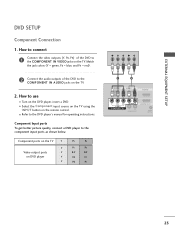
...red). 2 Connect the audio outputs of the DVD to the DVD player's manual for operating instructions. Component ports on the TV Y Y Video output ports Y on the remote control. EXTERNAL EQUIPMENT SETUP DVD SETUP Component Connection 1. How to use I Refer to the COMPONENT IN VIDEO jacks on the... TV. I Turn on the TV. 2. I Select the Component input source on the TV using the INPUT button on DVD player Y Y PB...
...red). 2 Connect the audio outputs of the DVD to the DVD player's manual for operating instructions. Component ports on the TV Y Y Video output ports Y on the remote control. EXTERNAL EQUIPMENT SETUP DVD SETUP Component Connection 1. How to use I Refer to the COMPONENT IN VIDEO jacks on the... TV. I Turn on the TV. 2. I Select the Component input source on the TV using the INPUT button on DVD player Y Y PB...
Owners Manual
Page 24
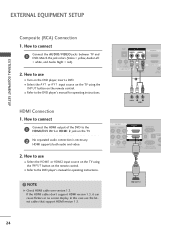
... a DVD. How to connect 1 Connect the HDMI output of the DVD to connect 1 Connect the AUDIO/VIDEO jacks between TV and DVD. NOTE G Check HDMI cable over version 1.3. EXTERNAL EQUIPMENT SETUP EXTERNAL EQUIPMENT SETUP Composite (RCA) Connection 1. How to the HDMI/DVI IN 1or HDMI 2 jack on the remote control. HDMI Connection 1. HDMI supports both audio and video. 2.
... a DVD. How to connect 1 Connect the HDMI output of the DVD to connect 1 Connect the AUDIO/VIDEO jacks between TV and DVD. NOTE G Check HDMI cable over version 1.3. EXTERNAL EQUIPMENT SETUP EXTERNAL EQUIPMENT SETUP Composite (RCA) Connection 1. How to the HDMI/DVI IN 1or HDMI 2 jack on the remote control. HDMI Connection 1. HDMI supports both audio and video. 2.
Owners Manual
Page 25
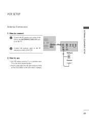
RGB IN (PC) DIO IN GB/DVI) OPTICAL DIGITAL AUDIO OUT RS-232C IN ACNATBELNENIAN/ CONTROL&SERVICE) 2. How to use I Insert a video tape into the VCR and press PLAY on the TV. 2 Connect the antenna cable to the same channel number. EXTERNAL EQUIPMENT SETUP VCR SETUP Antenna Connection 1. How to connect 1 ...Connect the RF antenna out socket of the VCR. I Set VCR output switch to 3 or 4 and then tune TV to the RF antenna in socket of the VCR to the ANTENNA/CABLE IN socket on the VCR. (Refer to the VCR owner's manual.) 1 ANT...
RGB IN (PC) DIO IN GB/DVI) OPTICAL DIGITAL AUDIO OUT RS-232C IN ACNATBELNENIAN/ CONTROL&SERVICE) 2. How to use I Insert a video tape into the VCR and press PLAY on the TV. 2 Connect the antenna cable to the same channel number. EXTERNAL EQUIPMENT SETUP VCR SETUP Antenna Connection 1. How to connect 1 ...Connect the RF antenna out socket of the VCR. I Set VCR output switch to 3 or 4 and then tune TV to the RF antenna in socket of the VCR to the ANTENNA/CABLE IN socket on the VCR. (Refer to the VCR owner's manual.) 1 ANT...
Owners Manual
Page 26
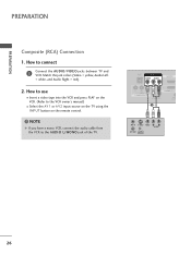
... SWITCH 26 How to use I Insert a video tape into the VCR and press PLAY on the VCR. (Refer to the AUDIO L/MONO jack of the TV. PREPARATION PREPARATION Composite (RCA) Connection 1. NOTE G If you have a mono VCR, connect the audio cable from the VCR to the VCR owner's manual.) I Select the...
... SWITCH 26 How to use I Insert a video tape into the VCR and press PLAY on the VCR. (Refer to the AUDIO L/MONO jack of the TV. PREPARATION PREPARATION Composite (RCA) Connection 1. NOTE G If you have a mono VCR, connect the audio cable from the VCR to the VCR owner's manual.) I Select the...
Owners Manual
Page 27
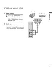
How to use I Operate the corresponding external equipment. PREPARATION OTHER A/V SOURCE SETUP 1. How to connect 1 Connect the AUDIO/VIDEO jacks between TV and external equipment. USB IN Camcorder Video Game Set VIDEO L R 1 VIDEO L/MONO AUDIO R AV IN 2 27 Match the jack colors. (Video = yellow, Audio Left = white, and Audio Right = red) 2. I Select the A V 1 or A V 2 input source on the TV using the INPUT button on the remote control.
How to use I Operate the corresponding external equipment. PREPARATION OTHER A/V SOURCE SETUP 1. How to connect 1 Connect the AUDIO/VIDEO jacks between TV and external equipment. USB IN Camcorder Video Game Set VIDEO L R 1 VIDEO L/MONO AUDIO R AV IN 2 27 Match the jack colors. (Video = yellow, Audio Left = white, and Audio Right = red) 2. I Select the A V 1 or A V 2 input source on the TV using the INPUT button on the remote control.
Owners Manual
Page 29
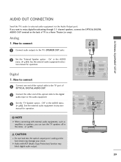
... ACP (Audio Copy Protection) function may damage your vision. If you can turn the TV speakers off in the menu. (G p.82) 1 RJP AV IN 1 VIDEO AUDIO 2 L(MONO) R 1 VIDEO COMPONENT IN L AUDIO R L R SPEAKER OUT AU (RG /DVI IN REMOTE CONTROL IN (C O 2 R 1 R R OUT RGB IN (PC) AUDIO IN OPTICAL DIGITAL AUDIO OUT /DVI IN...
... ACP (Audio Copy Protection) function may damage your vision. If you can turn the TV speakers off in the menu. (G p.82) 1 RJP AV IN 1 VIDEO AUDIO 2 L(MONO) R 1 VIDEO COMPONENT IN L AUDIO R L R SPEAKER OUT AU (RG /DVI IN REMOTE CONTROL IN (C O 2 R 1 R R OUT RGB IN (PC) AUDIO IN OPTICAL DIGITAL AUDIO OUT /DVI IN...
Owners Manual
Page 30
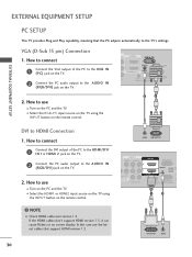
... A REMOTE RS-232C IN C CONTROL IN (CONTROL&SERVICE) 1 2 DVI OUTPUT AUDIO VGA (D-Sub 15 pin) Connection 1. How to the AUDIO IN (RGB/DVI) jack on the TV. 2. In this case use I Turn on the PC and the TV. How to connect 1 Connect the VGA output of the PC to the HDMI/DVI I Select the HDMI1 or... HDMI2 input source on the TV using the INPUT button on the remote control. 2 1 DVI to use I Turn on...
... A REMOTE RS-232C IN C CONTROL IN (CONTROL&SERVICE) 1 2 DVI OUTPUT AUDIO VGA (D-Sub 15 pin) Connection 1. How to the AUDIO IN (RGB/DVI) jack on the TV. 2. In this case use I Turn on the PC and the TV. How to connect 1 Connect the VGA output of the PC to the HDMI/DVI I Select the HDMI1 or... HDMI2 input source on the TV using the INPUT button on the remote control. 2 1 DVI to use I Turn on...
Owners Manual
Page 36
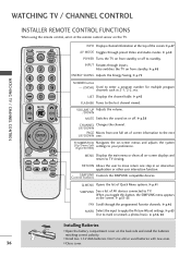
...step in an interactive application or other user interaction function. G p.38 CHANNEL Changes the channel. ControSlIMbuPtLtIoNnKs Controls the SIMPLINK compatible devices. G p.65 Use to TV viewing. Q.MENU Opens the list of AV devices connected to the next UP/DOWN one full set ...one . G p.51-53 FAV Scroll through the programmed Favorite channels. WATCHING TV / CHANNEL CONTROL WATCHING TV / CHANNEL CONTROL INSTALLER REMOTE CONTROL FUNCTIONS When using the remote control, aim it at the remote control sensor on or off to your preference. INFO POWER INPUT AV MODE ENERGY ...
...step in an interactive application or other user interaction function. G p.38 CHANNEL Changes the channel. ControSlIMbuPtLtIoNnKs Controls the SIMPLINK compatible devices. G p.65 Use to TV viewing. Q.MENU Opens the list of AV devices connected to the next UP/DOWN one full set ...one . G p.51-53 FAV Scroll through the programmed Favorite channels. WATCHING TV / CHANNEL CONTROL WATCHING TV / CHANNEL CONTROL INSTALLER REMOTE CONTROL FUNCTIONS When using the remote control, aim it at the remote control sensor on or off to your preference. INFO POWER INPUT AV MODE ENERGY ...
Owners Manual
Page 37
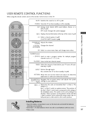
... Right) settings to standby. THUMBSTICK Navigates the on from standby or off to your TV turns off . I Install two 1.5V AAA batteries. INFO Displays channel information at the remote control sensor on from standby. TIMER Select the amount of time before your preference. Installing Batteries...switch on the back side and install the batteries matching correct polarity. Don't mix old or used batteries with new ones. WATCHING TV / CHANNEL CONTROL MUTE POWER SAP INFO CC CH OK VOL VOL CH 123 456 789 FLASHBK 0 TIMER INPUT RETURN BED1 BED2 MUTE Switches the...
... Right) settings to standby. THUMBSTICK Navigates the on from standby or off to your TV turns off . I Install two 1.5V AAA batteries. INFO Displays channel information at the remote control sensor on from standby. TIMER Select the amount of time before your preference. Installing Batteries...switch on the back side and install the batteries matching correct polarity. Don't mix old or used batteries with new ones. WATCHING TV / CHANNEL CONTROL MUTE POWER SAP INFO CC CH OK VOL VOL CH 123 456 789 FLASHBK 0 TIMER INPUT RETURN BED1 BED2 MUTE Switches the...
Owners Manual
Page 38
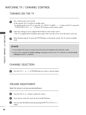
... press the POWER, INPUT, CH ( or ), Number (0~9) button on the remote control. At this moment, the TV switches to standby mode. ! I This TV is programmed to select a channel number. WATCHING TV / CHANNEL CONTROL WATCHING TV / CHANNEL CONTROL TURNING ON THE TV 1 First, connect power cord correctly. CHANNEL SELECTION 1 Press the CH ( or ) or NUMBER buttons to remember which...
... press the POWER, INPUT, CH ( or ), Number (0~9) button on the remote control. At this moment, the TV switches to standby mode. ! I This TV is programmed to select a channel number. WATCHING TV / CHANNEL CONTROL WATCHING TV / CHANNEL CONTROL TURNING ON THE TV 1 First, connect power cord correctly. CHANNEL SELECTION 1 Press the CH ( or ) or NUMBER buttons to remember which...
Owners Manual
Page 39
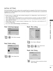
... Zone Daylight Saving F Auto G 02 21 2009 10 AM 10 Eastern Auto Previous Next 1 Select Auto or Manual. 2 ENTER Select desired time option. Step4. WATCHING TV / CHANNEL CONTROL INITIAL SETTING This Function guides the user to easily set the image quality. We recommend setting the... TV to "Home Use" mode for use this TV at store, select [Store Demo]. Store Demo Home Use Select [Home Use] to set the essential items for viewing the TV for the first time. "Store ...
... Zone Daylight Saving F Auto G 02 21 2009 10 AM 10 Eastern Auto Previous Next 1 Select Auto or Manual. 2 ENTER Select desired time option. Step4. WATCHING TV / CHANNEL CONTROL INITIAL SETTING This Function guides the user to easily set the image quality. We recommend setting the... TV to "Home Use" mode for use this TV at store, select [Store Demo]. Store Demo Home Use Select [Home Use] to set the essential items for viewing the TV for the first time. "Store ...
Owners Manual
Page 40
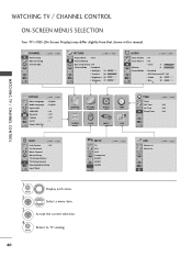
WATCHING TV / CHANNEL CONTROL WATCHING TV / CHANNEL CONTROL ON-SCREEN MENUS SELECTION Your TV's OSD (On Screen Display) may differ slightly from that shown in this manual. CHANNEL Auto Tuning Manual Tuning Channel Edit Move Enter PICTURE Move Enter ... Time Sleep Timer Move Enter : Off : Off : Off LOCK Move Enter Lock System : Off Set Password Block Channel Movie Rating TV Rating-Children TV Rating-General Downloadable Rating Input Block INPUT TV AV1 AV2 Component RGB-PC HDMI1 HDMI2 Move Enter USB Photo List Music List Move Enter 1 MENU 2 ENTER Display each menu...
WATCHING TV / CHANNEL CONTROL WATCHING TV / CHANNEL CONTROL ON-SCREEN MENUS SELECTION Your TV's OSD (On Screen Display) may differ slightly from that shown in this manual. CHANNEL Auto Tuning Manual Tuning Channel Edit Move Enter PICTURE Move Enter ... Time Sleep Timer Move Enter : Off : Off : Off LOCK Move Enter Lock System : Off Set Password Block Channel Movie Rating TV Rating-Children TV Rating-General Downloadable Rating Input Block INPUT TV AV1 AV2 Component RGB-PC HDMI1 HDMI2 Move Enter USB Photo List Music List Move Enter 1 MENU 2 ENTER Display each menu...


