
Owner's Manual
Page 1
OWNER'S MANUAL PLASMA TV Please read this manual carefully before operating your set and retain it for future reference. 42PT200 50PT200 42PT330 50PT330 42PT350 50PT350 50PV400 60PV400 50PV430 60PV430 50PV450 60PV450 42PT250U 50PT250U 50PV550U 60PV550U 42PT350C 50PT350C 50PV450C 60PV450C P/NO : SAC34173308 (1102-REV01) www.lg.com
OWNER'S MANUAL PLASMA TV Please read this manual carefully before operating your set and retain it for future reference. 42PT200 50PT200 42PT330 50PT330 42PT350 50PT350 50PV400 60PV400 50PV430 60PV430 50PV450 60PV450 42PT250U 50PT250U 50PV550U 60PV550U 42PT350C 50PT350C 50PV450C 60PV450C P/NO : SAC34173308 (1102-REV01) www.lg.com
Owner's Manual
Page 2
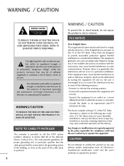
... If this device must accept any way without written authorization from that may be determined by turning the equipment off and on a circuit different from LG Electronics. Any changes or modifications not expressly approved by one or more of the National Electric Code (U.S.A.). NOTE TO CABLE.../TV INSTALLER This reminder is provided to call the CATV system installer's attention to Article 820-40 of the following two conditions: (1) This device may ...
... If this device must accept any way without written authorization from that may be determined by turning the equipment off and on a circuit different from LG Electronics. Any changes or modifications not expressly approved by one or more of the National Electric Code (U.S.A.). NOTE TO CABLE.../TV INSTALLER This reminder is provided to call the CATV system installer's attention to Article 820-40 of the following two conditions: (1) This device may ...
Owner's Manual
Page 4
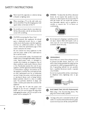
... this product near flammable objects such as this owner's manual to telephone wires, lightening rods, or gas pipes. on the wall, make the TV with something. 14 CAUTION concerning the Power Cord: It is recommend that appliance and has no additional outlets or branch circuits. Do not use ... the unit). 17 GROUNDING Ensure that you turn off this product to the same AC power outlet as gasoline or candles or expose the TV to direct air conditioning. 16 Do not expose to prevent possible electric shock (i.e. Short-circuit Breaker Power Supply 18 DISCONNECTING DEVICE FROM MAINS ...
... this product near flammable objects such as this owner's manual to telephone wires, lightening rods, or gas pipes. on the wall, make the TV with something. 14 CAUTION concerning the Power Cord: It is recommend that appliance and has no additional outlets or branch circuits. Do not use ... the unit). 17 GROUNDING Ensure that you turn off this product to the same AC power outlet as gasoline or candles or expose the TV to direct air conditioning. 16 Do not expose to prevent possible electric shock (i.e. Short-circuit Breaker Power Supply 18 DISCONNECTING DEVICE FROM MAINS ...
Owner's Manual
Page 5
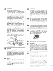
...by plastic thermal contraction due to temperature and humidity. Antenna grounding according to the National Electrical Code, ANSI/NFPA 70 23 Ventilation Install your TV where there is installed, follow the precautions below. Do not cover the product with a soft cloth to operate a product. Do not... a long period, the ventilation openings may become hot. Section 810 of the product. 5 Do not install in . When watching the TV for the grounding electrode. NEC: National Electrical Code 21 Cleaning When cleaning, unplug the power cord and scrub gently with cloth or other ...
...by plastic thermal contraction due to temperature and humidity. Antenna grounding according to the National Electrical Code, ANSI/NFPA 70 23 Ventilation Install your TV where there is installed, follow the precautions below. Do not cover the product with a soft cloth to operate a product. Do not... a long period, the ventilation openings may become hot. Section 810 of the product. 5 Do not install in . When watching the TV for the grounding electrode. NEC: National Electrical Code 21 Cleaning When cleaning, unplug the power cord and scrub gently with cloth or other ...
Owner's Manual
Page 6
... Reset 80 Demo Mode 80 Image Sticking Minimization (ISM) Method 81 6 CONTENTS WARNING / CAUTION 2 SAFETY INSTRUCTIONS 3 FEATURE OF THIS TV 8 PREPARATION Accessories 9 Front Panel Information 10 Back Panel Information 11 Stand Instruction 13 Cable Management 15 Desktop Pedestal Installation 16 Swivel Stand ...Setup 25 Other A/V Source Setup 26 USB Connection 26 Audio Out Connection 27 PC Setup 28 WATCHING TV / CHANNEL CONTROL Remote Control Functions 34 Turning On TV 36 Channel Selection 36 Volume Adjustment 36 Initial Setting 37 On-Screen Menus Selection 38 Quick Menu 39...
... Reset 80 Demo Mode 80 Image Sticking Minimization (ISM) Method 81 6 CONTENTS WARNING / CAUTION 2 SAFETY INSTRUCTIONS 3 FEATURE OF THIS TV 8 PREPARATION Accessories 9 Front Panel Information 10 Back Panel Information 11 Stand Instruction 13 Cable Management 15 Desktop Pedestal Installation 16 Swivel Stand ...Setup 25 Other A/V Source Setup 26 USB Connection 26 Audio Out Connection 27 PC Setup 28 WATCHING TV / CHANNEL CONTROL Remote Control Functions 34 Turning On TV 36 Channel Selection 36 Volume Adjustment 36 Initial Setting 37 On-Screen Menus Selection 38 Quick Menu 39...
Owner's Manual
Page 7
.../Off Time Setting 98 Sleep Timer Setting 99 PARENTAL CONTROL / RATINGS Set Password & Lock System 100 Channel Blocking 103 Movie & TV Rating 104 Downloadable Rating 109 External Input Blocking 110 Key lock 111 APPENDIX Troubleshooting 112 Maintenance 114 Product Specifications 114 IR Codes 116 ...External Control Through RS-232C 118 7 Analog Broadcasting System Captions 93 - User Mode 85 Infinite Surround 86 Balance 87 TV Speakers On/Off Setup 88 Audio Reset 89 Stereo/SAP Broadcast Setup 90 Audio Language 91 On-Screen Menus Language Selection 92 Caption ...
.../Off Time Setting 98 Sleep Timer Setting 99 PARENTAL CONTROL / RATINGS Set Password & Lock System 100 Channel Blocking 103 Movie & TV Rating 104 Downloadable Rating 109 External Input Blocking 110 Key lock 111 APPENDIX Troubleshooting 112 Maintenance 114 Product Specifications 114 IR Codes 116 ...External Control Through RS-232C 118 7 Analog Broadcasting System Captions 93 - User Mode 85 Infinite Surround 86 Balance 87 TV Speakers On/Off Setup 88 Audio Reset 89 Stereo/SAP Broadcast Setup 90 Audio Language 91 On-Screen Menus Language Selection 92 Caption ...
Owner's Manual
Page 8
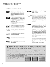
... 's surroundings, more information on how to 50% in ." Detailed calibration requires a licensed technician. High-definition television. Displays HDTV programs in your TV through the ISFccc mode. Using a sophisticated algorithm, the LG processes picture quality elements including brightness, contrast, color, sharpness and white balance. View videos and photos and listen to play purchased...
... 's surroundings, more information on how to 50% in ." Detailed calibration requires a licensed technician. High-definition television. Displays HDTV programs in your TV through the ISFccc mode. Using a sophisticated algorithm, the LG processes picture quality elements including brightness, contrast, color, sharpness and white balance. View videos and photos and listen to play purchased...
Owner's Manual
Page 9
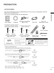
... the Ferrite Core 1. Wind the PC audio cable on the ferrite core once. If there is missing, please contact the dealer where you purchased the TV. If there are three ferrite cores, follow as shown in Figures 1 and 2. - If there are two ferrite cores, follow as shown in Figures 1 and 3. [... of Ferrite Core] 9 If an accessory is one ferrite core, follow as shown in the power cable. Place the ferrite core close to the TV. [to a wall plug] [Figure 2] [to reduce the electromagnetic interference in Figure 1. - The accessories included may cause (Not included with your...
... the Ferrite Core 1. Wind the PC audio cable on the ferrite core once. If there is missing, please contact the dealer where you purchased the TV. If there are three ferrite cores, follow as shown in Figures 1 and 2. - If there are two ferrite cores, follow as shown in Figures 1 and 3. [... of Ferrite Core] 9 If an accessory is one ferrite core, follow as shown in the power cable. Place the ferrite core close to the TV. [to a wall plug] [Figure 2] [to reduce the electromagnetic interference in Figure 1. - The accessories included may cause (Not included with your...
Owner's Manual
Page 10
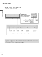
...VOL CH POWER INPUT Button Button HOME Button ENTER Button VOLUME Buttons You can operate the buttons just by touching them lightly with your TV. The floor or the product may be damaged. 10 ENTER VOL CH Intelligent Sensor Adjusts picture according to any impact. G Do not... drag the TV. Power/Standby Indicator Illuminates red in standby mode. The LED is off while the TV remains on the glass stand or subject it to the surrounding conditions. It may break, causing possible...
...VOL CH POWER INPUT Button Button HOME Button ENTER Button VOLUME Buttons You can operate the buttons just by touching them lightly with your TV. The floor or the product may be damaged. 10 ENTER VOL CH Intelligent Sensor Adjusts picture according to any impact. G Do not... drag the TV. Power/Standby Indicator Illuminates red in standby mode. The LED is off while the TV remains on the glass stand or subject it to the surrounding conditions. It may break, causing possible...
Owner's Manual
Page 12
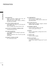
Supports standard definition video only (480i). 8 ANTENNA/CABLE IN Connect over-the air signals to operate the TV on DC power. 12 Doesn't support 480i. Supports HD. PREPARATION PREPARATION 1 HDMI/DVI IN Digital Connection. Accepts DVI video using an adapter or HDMI to ...
Supports standard definition video only (480i). 8 ANTENNA/CABLE IN Connect over-the air signals to operate the TV on DC power. 12 Doesn't support 480i. Supports HD. PREPARATION PREPARATION 1 HDMI/DVI IN Digital Connection. Accepts DVI video using an adapter or HDMI to ...
Owner's Manual
Page 13
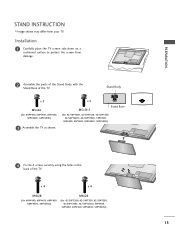
Stand Body x 3 M5x24 (For 60PV400, 60PV430, 60PV450, 60PV450C, 60PV550U) 3 Assemble the TV as shown. Installation 1 Carefully place the TV screen side down on a cushioned surface to protect the screen from your TV. x 3 M5x14.5 Stand Base (For 42/50PT200, 42/50PT330, 42/50PT350, 42/50PT350C, 42/50PT250U..., 50PV400, 50PV430, 50PV450, 50PV450C, 50PV550U) 4 Fix the 4 screws securely using the holes in the back of the TV. x 4 x 4 M4x28 (For 60PV400, 60PV430, 60PV450, 60PV450C, 60PV550U) M4x26 (For 42/50PT200, 42/50PT330, 42/50PT350, 42/50PT350C, 42/...
Stand Body x 3 M5x24 (For 60PV400, 60PV430, 60PV450, 60PV450C, 60PV550U) 3 Assemble the TV as shown. Installation 1 Carefully place the TV screen side down on a cushioned surface to protect the screen from your TV. x 3 M5x14.5 Stand Base (For 42/50PT200, 42/50PT330, 42/50PT350, 42/50PT350C, 42/50PT250U..., 50PV400, 50PV430, 50PV450, 50PV450C, 50PV550U) 4 Fix the 4 screws securely using the holes in the back of the TV. x 4 x 4 M4x28 (For 60PV400, 60PV430, 60PV450, 60PV450C, 60PV550U) M4x26 (For 42/50PT200, 42/50PT330, 42/50PT350, 42/50PT350C, 42/...
Owner's Manual
Page 14
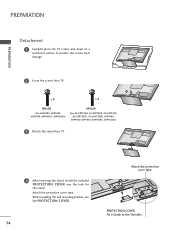
When installing the wall mounting bracket, use the PROTECTION COVER. 14 Attach the protection cover tape. PREPARATION PREPARATION Detachment 1 Carefully place the TV screen side down on a cushioned surface to the Outsides. x 4 x 4 M4x28 (For 60PV400, 60PV430, 60PV450, 60PV450C, 60PV550U) M4x26 (For 42/50PT200,... 42/50PT330, 42/50PT350, 42/50PT350C, 42/50PT250U, 50PV400, 50PV430, 50PV450, 50PV450C, 50PV550U) 3 Detach the stand from TV. Attach the protection cover tape. PROTECTION COVER Fix a Guide to protect the screen from damage. 2 Loose the screws from...
When installing the wall mounting bracket, use the PROTECTION COVER. 14 Attach the protection cover tape. PREPARATION PREPARATION Detachment 1 Carefully place the TV screen side down on a cushioned surface to the Outsides. x 4 x 4 M4x28 (For 60PV400, 60PV430, 60PV450, 60PV450C, 60PV550U) M4x26 (For 42/50PT200,... 42/50PT330, 42/50PT350, 42/50PT350C, 42/50PT250U, 50PV400, 50PV430, 50PV450, 50PV450C, 50PV550U) 3 Detach the stand from TV. Attach the protection cover tape. PROTECTION COVER Fix a Guide to protect the screen from damage. 2 Loose the screws from...
Owner's Manual
Page 15
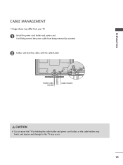
PREPARATION CABLE MANAGEMENT s Image shown may differ from being removed by holding the cable holder and power cord holder, as the cable holders may break, and injuries and damage to the TV may occur. 15 It will help prevent the power cable from your TV. 1 Install the power cord holder and power cord. POWER CORD HOLDER CABLE HOLDER CAUTION G Do not move the TV by accident. 2 Gather and bind the cables with the cable holder.
PREPARATION CABLE MANAGEMENT s Image shown may differ from being removed by holding the cable holder and power cord holder, as the cable holders may break, and injuries and damage to the TV may occur. 15 It will help prevent the power cable from your TV. 1 Install the power cord holder and power cord. POWER CORD HOLDER CABLE HOLDER CAUTION G Do not move the TV by accident. 2 Gather and bind the cables with the cable holder.
Owner's Manual
Page 16
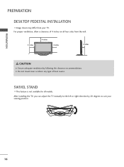
G Do not mount near or above any type of 4 inches on all models. After installing the TV, you can adjust the TV manually to the left or right direction by following the clearance recommendations. SWIVEL STAND s This feature is not available for all four sides from your viewing position. 16 For proper ventilation, allow a clearance of heat source. PREPARATION PREPARATION DESKTOP PEDESTAL INSTALLATION s Image shown may differ from the wall. 4 inches 4 inches 4 inches 4 inches CAUTION G Ensure adequate ventilation by 20 degrees to suit your TV.
G Do not mount near or above any type of 4 inches on all models. After installing the TV, you can adjust the TV manually to the left or right direction by following the clearance recommendations. SWIVEL STAND s This feature is not available for all four sides from your viewing position. 16 For proper ventilation, allow a clearance of heat source. PREPARATION PREPARATION DESKTOP PEDESTAL INSTALLATION s Image shown may differ from the wall. 4 inches 4 inches 4 inches 4 inches CAUTION G Ensure adequate ventilation by 20 degrees to suit your TV.
Owner's Manual
Page 17
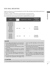
... wall mounting be performed by a qualified professional installer. PREPARATION VESA WALL MOUNTING Install your nearest installer. LG is not liable for TV damage or personal injury when a non-VESA or non specified wall mount is used . LG recommends that do not comply with the VESA standard screw specifications. NOTE G Screw length needed depends...
... wall mounting be performed by a qualified professional installer. PREPARATION VESA WALL MOUNTING Install your nearest installer. LG is not liable for TV damage or personal injury when a non-VESA or non specified wall mount is used . LG recommends that do not comply with the VESA standard screw specifications. NOTE G Screw length needed depends...
Owner's Manual
Page 18
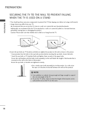
... it cannot be pulled in the product. Secure the wall brackets with the bolts (sold separately) to tie the product. Match the height of the TV. It is mounted on or hang from your product has the bolts in the eye-bolts position before inserting the eye-bolts, loosen the bolts.... * Insert the eye-bolts or TV brackets/bolts and tighten them securely in the picture. * If your TV. NOTE G Use a platform or cabinet strong enough and large enough to the wall as shown in the upper holes...
... it cannot be pulled in the product. Secure the wall brackets with the bolts (sold separately) to tie the product. Match the height of the TV. It is mounted on or hang from your product has the bolts in the eye-bolts position before inserting the eye-bolts, loosen the bolts.... * Insert the eye-bolts or TV brackets/bolts and tighten them securely in the picture. * If your TV. NOTE G Use a platform or cabinet strong enough and large enough to the wall as shown in the upper holes...
Owner's Manual
Page 19
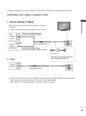
...adjust antenna direction if needed. RF Coaxial Wire (75 Ω) ANTENNA /CABLE IN I To prevent damage do not connect to wall jack for two TV's, install a 2-Way Signal Splitter. PREPARATION () VARIABLE AUDIO OUT R I To improve the picture quality in a poor signal area, please purchase a ...signal amplifier and install properly. Antenna (Analog or Digital) Wall Antenna Socket or Outdoor Antenna without a Cable Box Connection. Cable Cable TV Wall Jack RF Coaxial Wire (75 Ω) Single-family Dwellings /Houses (Connect to the power outlet until all connections are made between ...
...adjust antenna direction if needed. RF Coaxial Wire (75 Ω) ANTENNA /CABLE IN I To prevent damage do not connect to wall jack for two TV's, install a 2-Way Signal Splitter. PREPARATION () VARIABLE AUDIO OUT R I To improve the picture quality in a poor signal area, please purchase a ...signal amplifier and install properly. Antenna (Analog or Digital) Wall Antenna Socket or Outdoor Antenna without a Cable Box Connection. Cable Cable TV Wall Jack RF Coaxial Wire (75 Ω) Single-family Dwellings /Houses (Connect to the power outlet until all connections are made between ...
Owner's Manual
Page 20
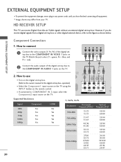
... (Y, PB, PR) of the digital set -top box. s Image shown may differ from a digital set -top box. HD RECEIVER SETUP This TV can receive Digital Over-the-air/Cable signals without an external digital set -top box or other digital external device, refer to COMPONENT IN 2 input...the remote control. Match the jack colors (Y = green, PB = blue, and PR = red). operation) s Select the Component1 input source on the TV using the INPUT button on the TV. 1 2 O IN /DVI) REMOTE CONTROL IN AV IN 1 VIDEO /MONO AUDIO 2 L R 1 VIDEO AUDIO COMPONENT IN ANT CA Supported Resolutions ...
... (Y, PB, PR) of the digital set -top box. s Image shown may differ from a digital set -top box. HD RECEIVER SETUP This TV can receive Digital Over-the-air/Cable signals without an external digital set -top box or other digital external device, refer to COMPONENT IN 2 input...the remote control. Match the jack colors (Y = green, PB = blue, and PR = red). operation) s Select the Component1 input source on the TV using the INPUT button on the TV. 1 2 O IN /DVI) REMOTE CONTROL IN AV IN 1 VIDEO /MONO AUDIO 2 L R 1 VIDEO AUDIO COMPONENT IN ANT CA Supported Resolutions ...
Owner's Manual
Page 21
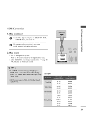
...) RGB IN(PC) ! In this case use I Turn on the digital set -top box.) I Select the HDMI1, 2, or 3 input source on the TV using the INPUT button on the TV. 2 No separate audio connection is necessary. HDMI-DTV Resolution Horizontal Frequency(KHz) 720x480p 1280x720p 1920x1080i 1920x1080p 31.47 31.47 44.96...
...) RGB IN(PC) ! In this case use I Turn on the digital set -top box.) I Select the HDMI1, 2, or 3 input source on the TV using the INPUT button on the TV. 2 No separate audio connection is necessary. HDMI-DTV Resolution Horizontal Frequency(KHz) 720x480p 1280x720p 1920x1080i 1920x1080p 31.47 31.47 44.96...
Owner's Manual
Page 22
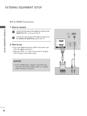
NOTE G A DVI to the AUDIO IN (RGB/DVI) jack on the TV. 2. DVI doesn't support audio, so a separate audio connection is required for the digital set-top ... to connect 1 Connect the DVI output of the digital set-top box to the HDMI/DVI IN 1 or 2 jack on the TV. 2 Connect the audio output of the digital set -top box. (Refer to HDMI Connection 1. How to use I Select the ...HDMI1 or 2 input source on the TV using the INPUT button on the digital set -top box to HDMI cable or adapter is necessary. EXTERNAL EQUIPMENT SETUP ...
NOTE G A DVI to the AUDIO IN (RGB/DVI) jack on the TV. 2. DVI doesn't support audio, so a separate audio connection is required for the digital set-top ... to connect 1 Connect the DVI output of the digital set-top box to the HDMI/DVI IN 1 or 2 jack on the TV. 2 Connect the audio output of the digital set -top box. (Refer to HDMI Connection 1. How to use I Select the ...HDMI1 or 2 input source on the TV using the INPUT button on the digital set -top box to HDMI cable or adapter is necessary. EXTERNAL EQUIPMENT SETUP ...


