
Owners Manual
Page 5
... Pedestal Installation 10 External Equipment Connections VCR Setup / Cable TV Setup 11 External A/V Source Setup 12 DVD Setup 12 DTV Setup 13 Monitor Output Setup 13 PC Setup 14~15 Basic Operation Turning the monitor On 16 Volume Adjustment 16 On-screen Menus Language Selection 16 On Screen Menus Selection and Adjustment . . .17 Picture Adjustment APC (Auto Picture Control 18 XD 18 Color Temperature Control 18 ACM 19 sRGB 19 Manual Picture Control(Off option 19 Audio Adjustment DASP (Digital Auto Sound Processing 20 BBE 20 AVL (Auto Volume Leveler 21 Manual Sound Control...
... Pedestal Installation 10 External Equipment Connections VCR Setup / Cable TV Setup 11 External A/V Source Setup 12 DVD Setup 12 DTV Setup 13 Monitor Output Setup 13 PC Setup 14~15 Basic Operation Turning the monitor On 16 Volume Adjustment 16 On-screen Menus Language Selection 16 On Screen Menus Selection and Adjustment . . .17 Picture Adjustment APC (Auto Picture Control 18 XD 18 Color Temperature Control 18 ACM 19 sRGB 19 Manual Picture Control(Off option 19 Audio Adjustment DASP (Digital Auto Sound Processing 20 BBE 20 AVL (Auto Volume Leveler 21 Manual Sound Control...
Owners Manual
Page 6
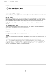
... Page 6 Introduction Introduction What is less than 5 inches thick. 160° - A plasma display panel is individually controlled by advanced electronics to produce colored light (red, green, or blue). Each sub-pixel is the latest display technology and the best way to react with excellent image quality and large screen sizes that is a Plasma Display Panel (PDP)? Versatile The light weight and thin size makes it work? These phosphors are easily viewable. over 16...
... Page 6 Introduction Introduction What is less than 5 inches thick. 160° - A plasma display panel is individually controlled by advanced electronics to produce colored light (red, green, or blue). Each sub-pixel is the latest display technology and the best way to react with excellent image quality and large screen sizes that is a Plasma Display Panel (PDP)? Versatile The light weight and thin size makes it work? These phosphors are easily viewable. over 16...

Owners Manual
Page 7
... INPUT MENU MULTIMEDIA ARC POWER MTS/ EXIT VOL ENTER VOL 1 2 4 3 5 7 6 8 APC 9 0 SPLIT ZOOM REVIEW/ A.PROG/ ERMAESME/ORY/ DASP SLEEP REW POWER FCR/ RECORD PLAY STOP FF STILL Owner's Manual Batteries Remote Control Power Cord D-sub 15 pin Cable Controls - Remote Control Sensor 4. Owner's Manual 7 INPUT SELECT Button 42PM3MV 3. Here shown may be somewhat different from standby or off to standby. Main Power Button Switches the set on . 2. Front Panel Controls 3 3 5 OK 4 12 42PM3MV ON/OFF 12 42/50PM1M 5 6 6 7 7 42/50PM1M 42...
... INPUT MENU MULTIMEDIA ARC POWER MTS/ EXIT VOL ENTER VOL 1 2 4 3 5 7 6 8 APC 9 0 SPLIT ZOOM REVIEW/ A.PROG/ ERMAESME/ORY/ DASP SLEEP REW POWER FCR/ RECORD PLAY STOP FF STILL Owner's Manual Batteries Remote Control Power Cord D-sub 15 pin Cable Controls - Remote Control Sensor 4. Owner's Manual 7 INPUT SELECT Button 42PM3MV 3. Here shown may be somewhat different from standby or off to standby. Main Power Button Switches the set on . 2. Front Panel Controls 3 3 5 OK 4 12 42PM3MV ON/OFF 12 42/50PM1M 5 6 6 7 7 42/50PM1M 42...
Owners Manual
Page 8
... this jack. Connection panels shown may be somewhat different from a PC to these jacks. 8 Plasma Monitor REMOTE CONTROL / AUDIO INPUT (for RGB, DVI) 4. VIDEO/AUDIO IN/OUT SOCKETS Connect the video/audio out sockets of an VCR to another set on an AC power. VARIABLE AUDIO OUTPUT 6. EXTERNAL SPEAKER (8 ohm output) Connect to optional external speaker(s). * For further information, refer to the RS-232C port on a PC. 2. Or connect a DVI(Video) signal. 3. POWER CORD SOCKET This set output connector from your Monitor. The voltage...
... this jack. Connection panels shown may be somewhat different from a PC to these jacks. 8 Plasma Monitor REMOTE CONTROL / AUDIO INPUT (for RGB, DVI) 4. VIDEO/AUDIO IN/OUT SOCKETS Connect the video/audio out sockets of an VCR to another set on an AC power. VARIABLE AUDIO OUTPUT 6. EXTERNAL SPEAKER (8 ohm output) Connect to optional external speaker(s). * For further information, refer to the RS-232C port on a PC. 2. Or connect a DVI(Video) signal. 3. POWER CORD SOCKET This set output connector from your Monitor. The voltage...

Owners Manual
Page 9
... PLAY FF RECORD STOP STILL POWER Turns your selection or displays the current mode. ARC Changes the picture format. Installing Batteries • Open the battery compartment cover on the back side and install the batteries matching correct polarity (+ with new ones. Don't mix old or used batteries with +, - APC Adjusts the factory preset picture according to the screen. Replace cover. MULTIMEDIA Selects: RGB,HDMI and Component input sources. E /D Selects menu...
... PLAY FF RECORD STOP STILL POWER Turns your selection or displays the current mode. ARC Changes the picture format. Installing Batteries • Open the battery compartment cover on the back side and install the batteries matching correct polarity (+ with new ones. Don't mix old or used batteries with +, - APC Adjusts the factory preset picture according to the screen. Replace cover. MULTIMEDIA Selects: RGB,HDMI and Component input sources. E /D Selects menu...

Owners Manual
Page 11
... on the remote control. If the 4:3 picture format is connected to the set cannot display TV programming unless a TV tuner device or cable TV converter box is used; Select the input source with using the INPUT button on the screen. In the event that you connect both Video and SVideo at the same time. the fixed images on the sides of time. For further information regarding cable TV service, contact your desired channel with the monitor. Insert a video tape...
... on the remote control. If the 4:3 picture format is connected to the set cannot display TV programming unless a TV tuner device or cable TV converter box is used; Select the input source with using the INPUT button on the screen. In the event that you connect both Video and SVideo at the same time. the fixed images on the sides of time. For further information regarding cable TV service, contact your desired channel with the monitor. Insert a video tape...

Owners Manual
Page 12
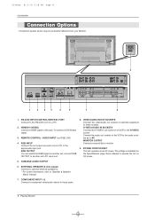
... DVD audio outputs to the AUDIO INPUT jacks on the set to use 1. Turn on the remote control. 2. U514Aen 81/11/9 2:28 PM Page 12 External Equipment Connections External A/V Source Setup How to connect Connect the audio and video cables from the external equipment's output jacks to the set input jacks, as shown in the figure. 2. Select the input source with using the INPUT button on the DVD player, insert a DVD. 2. Refer to the DVD player's manual for operating instructions. • Component Input ports To get better picture quality, connect a DVD player...
... DVD audio outputs to the AUDIO INPUT jacks on the set to use 1. Turn on the remote control. 2. U514Aen 81/11/9 2:28 PM Page 12 External Equipment Connections External A/V Source Setup How to connect Connect the audio and video cables from the external equipment's output jacks to the set input jacks, as shown in the figure. 2. Select the input source with using the INPUT button on the DVD player, insert a DVD. 2. Refer to the DVD player's manual for operating instructions. • Component Input ports To get better picture quality, connect a DVD player...
Owners Manual
Page 13
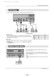
... INPUT 1 MONITOR OUTPUT A/V INPUT R L MONO AUDIO VIDEO S-VIDEO The set has a special signal output capability which allows you to connect Use the set's COMPONENT (Y, PB, PR) INPUT, RGB or HDMI/DVI jack for the digital set . External Equipment Connections REMOTE CONTROL RGB OUTPUT RS-232C INPUT (CONTROL/SERVICE) HDMI/ DVI(VIDEO) AUDIO INPUT RGB INPUT AUDIO R L VARIABLE AUDIO OUT R L EXTERNAL SPEAKER VIDEO CO CO R L AUDIO or or HDMI OUTPUT DVI-DTV OUTPUT (R) AUDIO (L) RGB-DTV OUTPUT B R (R) AUDIO (L) Digital Set-top Box How to hook up a second set - Use...
... INPUT 1 MONITOR OUTPUT A/V INPUT R L MONO AUDIO VIDEO S-VIDEO The set has a special signal output capability which allows you to connect Use the set's COMPONENT (Y, PB, PR) INPUT, RGB or HDMI/DVI jack for the digital set . External Equipment Connections REMOTE CONTROL RGB OUTPUT RS-232C INPUT (CONTROL/SERVICE) HDMI/ DVI(VIDEO) AUDIO INPUT RGB INPUT AUDIO R L VARIABLE AUDIO OUT R L EXTERNAL SPEAKER VIDEO CO CO R L AUDIO or or HDMI OUTPUT DVI-DTV OUTPUT (R) AUDIO (L) RGB-DTV OUTPUT B R (R) AUDIO (L) Digital Set-top Box How to hook up a second set - Use...
Owners Manual
Page 14
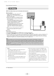
... set to display the PC on the set. • If the graphic card on the PC and the set 's RGB INPUT or HDMI/DVI (VIDEO) INPUT port for a long peri- Avoid keeping a fixed image on the screen. But in PC mode. Use the set . 2. Turn on the PC does output analog and digital RGB simultaneously, set the set to either RGB INPUT or HDMI/DVI (VIDEO) to Plug and Play automatically by pressing the POWER button on your service center. 14 Plasma Monitor Use...
... set to display the PC on the set. • If the graphic card on the PC and the set 's RGB INPUT or HDMI/DVI (VIDEO) INPUT port for a long peri- Avoid keeping a fixed image on the screen. But in PC mode. Use the set . 2. Turn on the PC does output analog and digital RGB simultaneously, set the set to either RGB INPUT or HDMI/DVI (VIDEO) to Plug and Play automatically by pressing the POWER button on your service center. 14 Plasma Monitor Use...
Owners Manual
Page 16
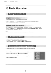
... power Set ID Caption / Text Demo OSD Rotate MENU Prev. Press the VOL F / G button to select Language. 3. Press the G button and then use D / E button to standby mode. 2. English Español Français 16 Plasma Monitor Turning on . NOTE • If you want to save. You can be shown in the selected language. Press the G button and then use D / E button to adjust the volume. 2. On-screen Menus Language Selection - Connect power cord...
... power Set ID Caption / Text Demo OSD Rotate MENU Prev. Press the VOL F / G button to select Language. 3. Press the G button and then use D / E button to standby mode. 2. English Español Français 16 Plasma Monitor Turning on . NOTE • If you want to save. You can be shown in the selected language. Press the G button and then use D / E button to adjust the volume. 2. On-screen Menus Language Selection - Connect power cord...
Owners Manual
Page 19
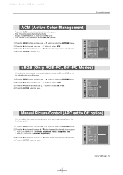
... 19 Picture Adjustment ACM (Active Color Management) - Press the G button and then use D / E button to select sRGB. 3. This feature is connected to external equipment using sRGB, set to select the PICTURE menu. 2. Press the G button and then use D / E button to Off option) - You can adjust picture contrast, brightness, color and sharpness options to select the desired skin color option. - Owner's Manual 19 Fleshtone 0 Greentone 0 Bluetone 0 sRGB (Only RGB-PC, DVI-PC Modes) - Press...
... 19 Picture Adjustment ACM (Active Color Management) - Press the G button and then use D / E button to select sRGB. 3. This feature is connected to external equipment using sRGB, set to select the PICTURE menu. 2. Press the G button and then use D / E button to Off option) - You can adjust picture contrast, brightness, color and sharpness options to select the desired skin color option. - Owner's Manual 19 Fleshtone 0 Greentone 0 Bluetone 0 sRGB (Only RGB-PC, DVI-PC Modes) - Press...
Owners Manual
Page 24
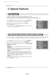
... when you turn the Monitor off. 1. SPECIAL Input Language Key lock ISM Method G Low power Set ID Caption / Text Demo OSD Rotate MENU Prev. Press the G button and then use D / E button to select either Normal, White wash, Orbiter or Inversion. • Normal If image sticking is never a problem, ISM is best not to allow any fixed image to prevent unauthorized viewing by locking out the front panel controls. - The Monitor can be set to...
... when you turn the Monitor off. 1. SPECIAL Input Language Key lock ISM Method G Low power Set ID Caption / Text Demo OSD Rotate MENU Prev. Press the G button and then use D / E button to select either Normal, White wash, Orbiter or Inversion. • Normal If image sticking is never a problem, ISM is best not to allow any fixed image to prevent unauthorized viewing by locking out the front panel controls. - The Monitor can be set to...

Owners Manual
Page 27
... screen may display an incorrect picture. 1. SCREEN Auto config. Press the ENTER button to adjust the position. 4. G Position Cinema NR Reset MENU Prev. 105 % FG Screen Position - Press the G button and then use D / E button to select Position. 3. Sets up the set for the best picture appearance for VGA/XGA mode in the SCREEN menu. - 42PM3MV model is only available in the following mode: Video or COMPONENT (480i). 1. Position Cinema G On NR Off Reset MENU Prev. Manual...
... screen may display an incorrect picture. 1. SCREEN Auto config. Press the ENTER button to adjust the position. 4. G Position Cinema NR Reset MENU Prev. 105 % FG Screen Position - Press the G button and then use D / E button to select Position. 3. Sets up the set for the best picture appearance for VGA/XGA mode in the SCREEN menu. - 42PM3MV model is only available in the following mode: Video or COMPONENT (480i). 1. Position Cinema G On NR Off Reset MENU Prev. Manual...
Owners Manual
Page 29
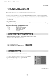
... is required to gain access to be viewed. To use the D / E button to block specific channels, ratings, and external viewing sources. - Set up with the initial password "0-0-0-0". Press the ENTER button to be blocked. 2. U514Aen 81/11/9 2:28 PM Page 29 Lock Adjustment Lock Adjustment Parental Control can be blocked by choosing the type of the program and the categories. Set ratings and categories to save. Enable the...
... is required to gain access to be viewed. To use the D / E button to block specific channels, ratings, and external viewing sources. - Set up with the initial password "0-0-0-0". Press the ENTER button to be blocked. 2. U514Aen 81/11/9 2:28 PM Page 29 Lock Adjustment Lock Adjustment Parental Control can be blocked by choosing the type of the program and the categories. Set ratings and categories to save. Enable the...

Owners Manual
Page 33
... panel. - Connect the serial port of Connector; RS-232C connection cables are not supplied with the Monitor. - U514Aen 81/11/9 2:28 PM Page 33 External Control Device Setup Appendix External Control Device Setup - D-Sub 9-Pin Male No. RS-232C connection cables are used for service. Connect the RS-232C input jack to an external control device (such as a computer or an A/V control system) and control the Monitor's functions externally. - RS-232C Setup REMOTE CONTROL RGB OUTPUT RS-232C INPUT (CONTROL/SERVICE) HDMI/ DVI(VIDEO) AUDIO INPUT RGB INPUT AUDIO R L VARIABLE AUDIO...
... panel. - Connect the serial port of Connector; RS-232C connection cables are not supplied with the Monitor. - U514Aen 81/11/9 2:28 PM Page 33 External Control Device Setup Appendix External Control Device Setup - D-Sub 9-Pin Male No. RS-232C connection cables are used for service. Connect the RS-232C input jack to an external control device (such as a computer or an A/V control system) and control the Monitor's functions externally. - RS-232C Setup REMOTE CONTROL RGB OUTPUT RS-232C INPUT (CONTROL/SERVICE) HDMI/ DVI(VIDEO) AUDIO INPUT RGB INPUT AUDIO R L VARIABLE AUDIO...
Owners Manual
Page 34
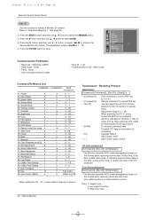
...: None * Use a crossed (reverse) cable. • Stop bit : 1 bit • Communication code : ASCII code Command Reference List COMMAND 1 COMMAND 2 DATA (Hexadecimal) 01. Brightness k 09. Remote control lock mode k 14. Green Adjustment k 21. At this function to choose desired monitor ID number in special menu. OSD Select k 13. Red Adjustment k 20. Blue Adjustment k 22. Error Acknowledgement [Command2][ ][Set ID][ ][NG][Data][x] * The Monitor transmits ACK (acknowledgement) based on screen. 34 Plasma Monitor Transmission / Receiving Protocol Transmission...
...: None * Use a crossed (reverse) cable. • Stop bit : 1 bit • Communication code : ASCII code Command Reference List COMMAND 1 COMMAND 2 DATA (Hexadecimal) 01. Brightness k 09. Remote control lock mode k 14. Green Adjustment k 21. At this function to choose desired monitor ID number in special menu. OSD Select k 13. Red Adjustment k 20. Blue Adjustment k 22. Error Acknowledgement [Command2][ ][Set ID][ ][NG][Data][x] * The Monitor transmits ACK (acknowledgement) based on screen. 34 Plasma Monitor Transmission / Receiving Protocol Transmission...
Owners Manual
Page 36
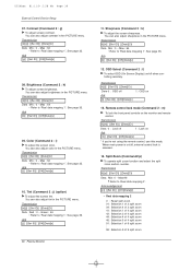
...][Data][x] 10. Transmission [k][j][ ][Set ID][ ][Data][Cr] Data Red : 0 ~ Green : 64 * Refer to 'Real data mapping 1'. You can also adjust sharpness in the PICTURE menu. OSD Select (Command 2 : l) G To select OSD (On Screen Display) on/off 1 : Lock on Ack [m][ ][Set ID][ ][OK][Data][x] * If you're not using the remote control, use this mode. Acknowledgement [p][ ][Set ID][ ][OK][Data][x] * Real data mapping 2 0 : Reset split zoom 21: Selection...
...][Data][x] 10. Transmission [k][j][ ][Set ID][ ][Data][Cr] Data Red : 0 ~ Green : 64 * Refer to 'Real data mapping 1'. You can also adjust sharpness in the PICTURE menu. OSD Select (Command 2 : l) G To select OSD (On Screen Display) on/off 1 : Lock on Ack [m][ ][Set ID][ ][OK][Data][x] * If you're not using the remote control, use this mode. Acknowledgement [p][ ][Set ID][ ][OK][Data][x] * Real data mapping 2 0 : Reset split zoom 21: Selection...
Owners Manual
Page 41
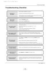
... wall power outlet, plug another product's power cord into the outlet where the Monitor's power cord was plugged in an unusual noise when the plasma display is turned on • This is normal, the image is muted during the Monitor startup process. Owner's Manual 41 No or poor color or poor picture • Select Color in the Picture menu and press the VOLUME (G) button. (Refer to p.9) Picture appears slowly after five minutes. The remote control doesn't work...
... wall power outlet, plug another product's power cord into the outlet where the Monitor's power cord was plugged in an unusual noise when the plasma display is turned on • This is normal, the image is muted during the Monitor startup process. Owner's Manual 41 No or poor color or poor picture • Select Color in the Picture menu and press the VOLUME (G) button. (Refer to p.9) Picture appears slowly after five minutes. The remote control doesn't work...
Owners Manual
Page 43
... your bill of sale or proof of sale to reach you promptly should we discover a safety or reliability problem that vary from state to state. Replacement Units and Repair Parts are warranted for instructions on getting the defective unit repaired or replaced. Some states do not allow us to the original consumer/end user. CONCERNING PIXEL FUNCTIONALITY: Your Plasma TV contains...
... your bill of sale or proof of sale to reach you promptly should we discover a safety or reliability problem that vary from state to state. Replacement Units and Repair Parts are warranted for instructions on getting the defective unit repaired or replaced. Some states do not allow us to the original consumer/end user. CONCERNING PIXEL FUNCTIONALITY: Your Plasma TV contains...

Owners Manual
Page 44
... in shipping or transit G service required as a result of improper installation, including incorrect or insufficient AC supply (please consult the owner's manual for power supply requirements) G installation or repair of antenna systems, cable converters, cable company supplied equipment, or other components in a video system G set-up or adjustment on consumer controls, or damage caused by improper adjustments G damage caused by other system components G any panel that unit in obtaining...
... in shipping or transit G service required as a result of improper installation, including incorrect or insufficient AC supply (please consult the owner's manual for power supply requirements) G installation or repair of antenna systems, cable converters, cable company supplied equipment, or other components in a video system G set-up or adjustment on consumer controls, or damage caused by improper adjustments G damage caused by other system components G any panel that unit in obtaining...


