Owners Manual
Page 2
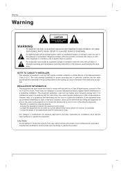
... equipment and receiver. - NOTE TO CABLE/TV INSTALLER: This reminder is connected. - Any changes or modifications not expressly approved by one or more of the cable entry as close to radio or television reception, which the receiver is provided to call the CATV system installer's attention to constitute a risk of important operating and maintenance (servicing) instructions in the literature accompanying the...
... equipment and receiver. - NOTE TO CABLE/TV INSTALLER: This reminder is connected. - Any changes or modifications not expressly approved by one or more of the cable entry as close to radio or television reception, which the receiver is provided to call the CATV system installer's attention to constitute a risk of important operating and maintenance (servicing) instructions in the literature accompanying the...

Owners Manual
Page 5
... Out Setup Digital Audio Output PC Setup 29 29 29 29 30 31 31 32 33 33 34 35 35~36 37 38 39 40 41 41~42 43 43 Turning on the TV Volume Adjustment Channel Selection On Screen Menus Language Selection On Screen Menus Selection and Adjustment EZ Scan (Channel Search) Manual Scan Channel Edit DTV Signal Strength Input Source Input Label Auto Picture Control(EZ Picture) Color Temperature Control XD Advanced-Cinema 3:2 Mode / Black Level Video Reset Audio Language Auto Sound Control(EZ Sound) Manual Sound Control (EZ Sound-User...
... Out Setup Digital Audio Output PC Setup 29 29 29 29 30 31 31 32 33 33 34 35 35~36 37 38 39 40 41 41~42 43 43 Turning on the TV Volume Adjustment Channel Selection On Screen Menus Language Selection On Screen Menus Selection and Adjustment EZ Scan (Channel Search) Manual Scan Channel Edit DTV Signal Strength Input Source Input Label Auto Picture Control(EZ Picture) Color Temperature Control XD Advanced-Cinema 3:2 Mode / Black Level Video Reset Audio Language Auto Sound Control(EZ Sound) Manual Sound Control (EZ Sound-User...
Owners Manual
Page 7
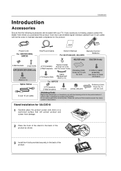
... be cautious of the product. 7 User must use shielded signal interface cables(D-sub 15 pin cable) with the cleansing cloths for the product. If any accessory is stain or fingerprint on surface of the exterior. Power Cord 75Ω Round Cable Owner's Manual TV INPUT TV AUDIO POWER DAY - For 60PC1D 2-TV brackets 2-Wall brackets 4- Stand Installation for 32LC2D/U 1 Carefully place the product screen side down on the exterior...
... be cautious of the product. 7 User must use shielded signal interface cables(D-sub 15 pin cable) with the cleansing cloths for the product. If any accessory is stain or fingerprint on surface of the exterior. Power Cord 75Ω Round Cable Owner's Manual TV INPUT TV AUDIO POWER DAY - For 60PC1D 2-TV brackets 2-Wall brackets 4- Stand Installation for 32LC2D/U 1 Carefully place the product screen side down on the exterior...

Owners Manual
Page 9
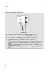
... the appropriate input port. 2 AV OUT Connect a second TV or monitor. 3 AV (Audio/Video) IN 1 Connect audio/video output from an external device to the RS-232C port on DC power. Introduction Connection Options (Model Name: 42PC3D/3DC/3DV/3DVA, 50PC3D, 60PC1D) - AUDIO COMPONENT IN AV OUT AV IN 1 COMPONENT IN AV OUT AV IN 1 6 HDMI IN VIDEO AUDIO Connect a HDMI signal to HDMI cable. Or DVI (VIDEO)signal to the 1(DVI) port with AC power. Note: In standby mode, these jacks. S-VIDEO VIDEO ( ) AUDIO 9 S-VIDEO VIDEO ( ) AUDIO This picture shown...
... the appropriate input port. 2 AV OUT Connect a second TV or monitor. 3 AV (Audio/Video) IN 1 Connect audio/video output from an external device to the RS-232C port on DC power. Introduction Connection Options (Model Name: 42PC3D/3DC/3DV/3DVA, 50PC3D, 60PC1D) - AUDIO COMPONENT IN AV OUT AV IN 1 COMPONENT IN AV OUT AV IN 1 6 HDMI IN VIDEO AUDIO Connect a HDMI signal to HDMI cable. Or DVI (VIDEO)signal to the 1(DVI) port with AC power. Note: In standby mode, these jacks. S-VIDEO VIDEO ( ) AUDIO 9 S-VIDEO VIDEO ( ) AUDIO This picture shown...

Owners Manual
Page 11
...DVI) OPTICAL CABLE IN RS-232C IN (CONTROL & SERVICE) DIGITAL AUDIO OUT S-VIDEO VIDEO (MONO) AUDIO 3 AV OUT 1 COMPONENT IN Connect a component these jacks. 9 video/audio device toS-VIDEO VIDEO AV IN 1 7 RGB IN (PC) ( ) AUDIO Connect the monitor output from a PC to the appropriate input port. 2 AV OUT Connect a second TV or monitor. 3 AV (Audio/Video) IN 1 Connect audio/video output from a PC to the appropriate input port. 9 RS-232C IN (CONTROL & SERVICE) PORT Connect to the RS-232C port on DC power. 6 HDMI IN Connect a HDMI signal to these ports do not work. 8 Remote Control...
...DVI) OPTICAL CABLE IN RS-232C IN (CONTROL & SERVICE) DIGITAL AUDIO OUT S-VIDEO VIDEO (MONO) AUDIO 3 AV OUT 1 COMPONENT IN Connect a component these jacks. 9 video/audio device toS-VIDEO VIDEO AV IN 1 7 RGB IN (PC) ( ) AUDIO Connect the monitor output from a PC to the appropriate input port. 2 AV OUT Connect a second TV or monitor. 3 AV (Audio/Video) IN 1 Connect audio/video output from a PC to the appropriate input port. 9 RS-232C IN (CONTROL & SERVICE) PORT Connect to the RS-232C port on DC power. 6 HDMI IN Connect a HDMI signal to these ports do not work. 8 Remote Control...

Owners Manual
Page 19
... channel number. 4 Insert a video tape into the VCR and press PLAY on the VCR. (Refer to the Antenna socket on the remote control. - the fixed images on the sides of the VCR to the VCR owner's manual.) 3 Select AV1 input source using the INPUT button on the set . When connecting with an antenna 2 VCR ANT IN ANT OUT S-VIDEO OUT OUTPUT SWITCH 34 (R) AUDIO (L) IN VIDEO SERVICE 1 RGB IN (PC) ANTENNA/ CABLSEEIRNVICE HDMI IN 2 1(DVI) AUDIO IN REMOTE (RGB/DVI) CONTROL IN RGBRISN-232C IN ((CPOCN)TROL & SERVICE) AUDIO...
... channel number. 4 Insert a video tape into the VCR and press PLAY on the VCR. (Refer to the Antenna socket on the remote control. - the fixed images on the sides of the VCR to the VCR owner's manual.) 3 Select AV1 input source using the INPUT button on the set . When connecting with an antenna 2 VCR ANT IN ANT OUT S-VIDEO OUT OUTPUT SWITCH 34 (R) AUDIO (L) IN VIDEO SERVICE 1 RGB IN (PC) ANTENNA/ CABLSEEIRNVICE HDMI IN 2 1(DVI) AUDIO IN REMOTE (RGB/DVI) CONTROL IN RGBRISN-232C IN ((CPOCN)TROL & SERVICE) AUDIO...

Owners Manual
Page 20
... Setup Camcorder Video Game Set 1 L AUDIO R VIDEO 1 Connect the AUDIO/VIDEO jacks between TV and external equipment. Match the jack colors (Video = yellow, Audio Left = white, and Audio Right = red). 2 Select AV2 input source with using the INPUT button on the remote control. - Refer to AV IN2, select AV2 input source. Installation COMPONENT IN AV OUT AV IN 1 VIDEO AUDIO OPTICAL DIGITAL AUDIO S-VIDEO VIDEO ( ) AUDIO When conOUnT ecting with using the INPUT button on the remote control. - compared to normal composite (RCA cable) input. 2 Connect the audio outputs of the VCR...
... Setup Camcorder Video Game Set 1 L AUDIO R VIDEO 1 Connect the AUDIO/VIDEO jacks between TV and external equipment. Match the jack colors (Video = yellow, Audio Left = white, and Audio Right = red). 2 Select AV2 input source with using the INPUT button on the remote control. - Refer to AV IN2, select AV2 input source. Installation COMPONENT IN AV OUT AV IN 1 VIDEO AUDIO OPTICAL DIGITAL AUDIO S-VIDEO VIDEO ( ) AUDIO When conOUnT ecting with using the INPUT button on the remote control. - compared to normal composite (RCA cable) input. 2 Connect the audio outputs of the VCR...

Owners Manual
Page 21
...DIGITAL AUDIO OUT S-VIDEO VIDEO (MONO) AUDIO 1 Connect the S-VIDEO output of the DVD to the S-VIDEO input on the set. 2 Connect the audio outputs of the DVD to the AUDIO input jacks on the set. 3 Turn on the DVD player, insert a DVD. 4 Select AV1 input source with using the INPUT button on the remote control. 3 Refer to the DVD player's manual for operating instructions. VIDEO AUDIO COMPONENT IN AV OUT AV IN 1 OPTICAL DIGITAL AUDIO OUT S-VIDEO VIDEO ( ) AUDIO • TV can receive the video and audio signal simultaneously with using a HDMI cable. • If the DVD supports Auto...
...DIGITAL AUDIO OUT S-VIDEO VIDEO (MONO) AUDIO 1 Connect the S-VIDEO output of the DVD to the S-VIDEO input on the set. 2 Connect the audio outputs of the DVD to the AUDIO input jacks on the set. 3 Turn on the DVD player, insert a DVD. 4 Select AV1 input source with using the INPUT button on the remote control. 3 Refer to the DVD player's manual for operating instructions. VIDEO AUDIO COMPONENT IN AV OUT AV IN 1 OPTICAL DIGITAL AUDIO OUT S-VIDEO VIDEO ( ) AUDIO • TV can receive the video and audio signal simultaneously with using a HDMI cable. • If the DVD supports Auto...

Owners Manual
Page 23
...-air/Cable signals without an external digital set . When connecting with using the INPUT button on the remote control. 3 Turn on the digital set-top box. (Refer to the owner's manual for the digita(ClONTsROLe&StER-VtICoE) p box.) 4 Select Component 1 input source with a Component cable RS-232C IN (CONTROL & SERVICE) Digital Set-top Box B R (R) AUDIO (L) 1 2 VIDEO AUDIO 1 Connect the video outputs (Y, PB, PR) of the digiSERVICE tal set-top box to the COMPONENT IN AUDIO jacks on the set -top box. priately. If connected to 1280x720p. Installation HDSTB Setup - HDMI / DVI IN...
...-air/Cable signals without an external digital set . When connecting with using the INPUT button on the remote control. 3 Turn on the digital set-top box. (Refer to the owner's manual for the digita(ClONTsROLe&StER-VtICoE) p box.) 4 Select Component 1 input source with a Component cable RS-232C IN (CONTROL & SERVICE) Digital Set-top Box B R (R) AUDIO (L) 1 2 VIDEO AUDIO 1 Connect the video outputs (Y, PB, PR) of the digiSERVICE tal set-top box to the COMPONENT IN AUDIO jacks on the set -top box. priately. If connected to 1280x720p. Installation HDSTB Setup - HDMI / DVI IN...
Owners Manual
Page 24
... VIDEO AUDIO OPTICAL DIGITAL AUDIO OUT S-VIDEO VIDEO ( ) AUDIO When connecting with using the INPUT button on the set. RGB IN 3 Turn on the digital set-top box. (Refer to the owner's manual for the d(PCi)gital set-top box.) REMORTEGBAIUNDIO IN CONTROL IN (RGB/DVI) 4 Select HDMI1/DVI input source with a HDMI to DVI cable SERVICE HDMI IN 2 1(DVI) 1 RGB IN (PC) AUDIO IN REMOTE (RGB/DVI) CONTROL IN RS-232C IN (CONTROL & SERVICE) 2 COMPONENT IN AV OUT AV IN 1 1(DVI) RS-232C IN (CONTROL & SERVICE) DVI-DTV OUTPUT (R) AUDIO (L) Digital Set-top Box 1 Connect the DVI output of the digital...
... VIDEO AUDIO OPTICAL DIGITAL AUDIO OUT S-VIDEO VIDEO ( ) AUDIO When connecting with using the INPUT button on the set. RGB IN 3 Turn on the digital set-top box. (Refer to the owner's manual for the d(PCi)gital set-top box.) REMORTEGBAIUNDIO IN CONTROL IN (RGB/DVI) 4 Select HDMI1/DVI input source with a HDMI to DVI cable SERVICE HDMI IN 2 1(DVI) 1 RGB IN (PC) AUDIO IN REMOTE (RGB/DVI) CONTROL IN RS-232C IN (CONTROL & SERVICE) 2 COMPONENT IN AV OUT AV IN 1 1(DVI) RS-232C IN (CONTROL & SERVICE) DVI-DTV OUTPUT (R) AUDIO (L) Digital Set-top Box 1 Connect the DVI output of the digital...

Owners Manual
Page 25
... signal output capability which allows you to p.43) CAUTION Do not look into the optical output port. Send the TV's audio to use the video and audio output jacks for VCR recording. Installation AV Out Setup - COMPONENT IN AV OUT AV IN 1 VIDEO AUDIO OPTICAL DIGITAL AUDIO OUT S-VIDEO VIDEO (MONO) AUDIO 1 Connect the second TV or monitor to the TV's AV OUT jacks. 2 See the Operating Manual of the optical cable to the digital audio optical input on the audio equipment. 3 See the external audio equipment instruction manual...
... signal output capability which allows you to p.43) CAUTION Do not look into the optical output port. Send the TV's audio to use the video and audio output jacks for VCR recording. Installation AV Out Setup - COMPONENT IN AV OUT AV IN 1 VIDEO AUDIO OPTICAL DIGITAL AUDIO OUT S-VIDEO VIDEO (MONO) AUDIO 1 Connect the second TV or monitor to the TV's AV OUT jacks. 2 See the Operating Manual of the optical cable to the digital audio optical input on the audio equipment. 3 See the external audio equipment instruction manual...

Owners Manual
Page 26
...) jack on the set. 2 Connect the PC audio outputs to the AUDIO IN(RGB/DVI) jack on the set. 3 Turn on the PC and the set . 4 Select HDMI1/DVI input source with using the INPUT button on the remote control. AUDIO RGB-PC OUTPUT PC When connecting with a HDMI to DVI cable SERVICE HDMI IN 2 1(DVI) 1 RGB IN (PC) AUDIO IN REMOTE (RGB/DVI) CONTROL IN RS-232C IN (CONTROL & SERVICE) 2 DVI-PC OUTPUT AUDIO PC 1 Connect the DVI output of the PC to the HDMI IN 1(DVI) jack on the set. 2 Connect the audio outputs of...
...) jack on the set. 2 Connect the PC audio outputs to the AUDIO IN(RGB/DVI) jack on the set. 3 Turn on the PC and the set . 4 Select HDMI1/DVI input source with using the INPUT button on the remote control. AUDIO RGB-PC OUTPUT PC When connecting with a HDMI to DVI cable SERVICE HDMI IN 2 1(DVI) 1 RGB IN (PC) AUDIO IN REMOTE (RGB/DVI) CONTROL IN RS-232C IN (CONTROL & SERVICE) 2 DVI-PC OUTPUT AUDIO PC 1 Connect the DVI output of the PC to the HDMI IN 1(DVI) jack on the set. 2 Connect the audio outputs of...

Owners Manual
Page 27
... connected Cable or poor cable connection, "NO SIGNAL" OSD display in HDMI/DVI Source Devices, "INVALID FORMAT" OSD display. Avoid keeping a fixed image on your service center. 5. When Source Devices connected with HDMI/DVI Input, output PC Resolution (VGA, SVGA, XGA, WXGA), Position and Size may be changed, change the refresh rate to another resolution, change the PC graphic card or consult the manufacturer of HDMI/DVI Source Devices or contact your TV. The fixed image may not work if a HDMI...
... connected Cable or poor cable connection, "NO SIGNAL" OSD display in HDMI/DVI Source Devices, "INVALID FORMAT" OSD display. Avoid keeping a fixed image on your service center. 5. When Source Devices connected with HDMI/DVI Input, output PC Resolution (VGA, SVGA, XGA, WXGA), Position and Size may be changed, change the refresh rate to another resolution, change the PC graphic card or consult the manufacturer of HDMI/DVI Source Devices or contact your TV. The fixed image may not work if a HDMI...

Owners Manual
Page 28
... EZ SOUND SAP CC ADJUST ADJUST - When RGB connect to select Yes. 3 Press ENTER button. And the horizontal screen size will also change the resolution, select the proper resolution in present input to see the best picture appearance. * Initializing (Reset to make appropriate adjustments. • The PHASE adjustment range is -16 ~ +16. (In HDMI/DVI-PC mode, PHASE is not available.) • The SIZE adjustment range is -30 ~ +30. (In HDMI/DVI-PC mode, SIZE is used . - Installation Screen Setup for screen Resolution, Position, Size...
... EZ SOUND SAP CC ADJUST ADJUST - When RGB connect to select Yes. 3 Press ENTER button. And the horizontal screen size will also change the resolution, select the proper resolution in present input to see the best picture appearance. * Initializing (Reset to make appropriate adjustments. • The PHASE adjustment range is -16 ~ +16. (In HDMI/DVI-PC mode, PHASE is not available.) • The SIZE adjustment range is -30 ~ +30. (In HDMI/DVI-PC mode, SIZE is used . - Installation Screen Setup for screen Resolution, Position, Size...

Owners Manual
Page 29
... by using the TV, press the POWER button on the remote control . 2. Press the VOL D / E button to turn TV on, press the , INPUT, CH D / E button on the TV or press the POWER, TV INPUT, INPUT, CH D / E, Number (0 ~ 9) button on the remote control. In standby mode to adjust the volume. 2. This TV is programmed to remember which power state it was last set to select your desired language. Volume Adjustment 1. You can be shown on the remote control. Channel Selection...
... by using the TV, press the POWER button on the remote control . 2. Press the VOL D / E button to turn TV on, press the , INPUT, CH D / E button on the TV or press the POWER, TV INPUT, INPUT, CH D / E, Number (0 ~ 9) button on the remote control. In standby mode to adjust the volume. 2. This TV is programmed to remember which power state it was last set to select your desired language. Volume Adjustment 1. You can be shown on the remote control. Channel Selection...
Owners Manual
Page 30
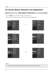
Operation On Screen Menus Selection and Adjustment How to select each menu. 2. EZ Scan Manual Scan Channel Edit DTV Signal Input Source Input Label Set ID EZ Picture Color Temperature XD Advanced Video Reset Lock System Set Password Block Channel Movie Rating TV Rating-Children TV Rating-General Input Block Audio Language EZ Sound Balance TV Speaker Aspect Ratio Caption/Text Caption Option Language ISM Method Low Power Auto Clock Manual Clock Off Timer On Timer Sleep Timer Auto Off • Your TV's OSD (On Screen Display) may differ slightly from...
Operation On Screen Menus Selection and Adjustment How to select each menu. 2. EZ Scan Manual Scan Channel Edit DTV Signal Input Source Input Label Set ID EZ Picture Color Temperature XD Advanced Video Reset Lock System Set Password Block Channel Movie Rating TV Rating-Children TV Rating-General Input Block Audio Language EZ Sound Balance TV Speaker Aspect Ratio Caption/Text Caption Option Language ISM Method Low Power Auto Clock Manual Clock Off Timer On Timer Sleep Timer Auto Off • Your TV's OSD (On Screen Display) may differ slightly from...

Owners Manual
Page 31
... start DIGITAL ANTENNA channel scan. Processing EZ scan... TV Ch.20 0 channel(s) found Press to delete the channel. - A password is required to gain access to EZ Scan menu if the Lock System is turned on. 1 Press the MENU button and then use D / E button to select the SETUP menu. 2 Press the G button and then use D / E button to select channel number you to the previous menu. 31 Manual Scan EZ Scan Manual Scan Channel Edit DTV Signal Input Source Input Label Set ID EZ Scan Manual Scan Channel Edit DTV Signal Input Source Input Label Set ID Select channel type...
... start DIGITAL ANTENNA channel scan. Processing EZ scan... TV Ch.20 0 channel(s) found Press to delete the channel. - A password is required to gain access to EZ Scan menu if the Lock System is turned on. 1 Press the MENU button and then use D / E button to select the SETUP menu. 2 Press the G button and then use D / E button to select channel number you to the previous menu. 31 Manual Scan EZ Scan Manual Scan Channel Edit DTV Signal Input Source Input Label Set ID EZ Scan Manual Scan Channel Edit DTV Signal Input Source Input Label Set ID Select channel type...

Owners Manual
Page 51
... programming. Operation Lock Menu Options Parental Control can be blocked by the type of program and by the categories chosen to be blocked. Enable the lock V-Chip rating and categories Rating guidelines are provided by TV Rating and/or Individual Categories. It is to allow all programming) Input Block • AV 1, 2 (On, Off) • Component 1, 2 (On, Off) • RGB-PC, HDMI1/DVI and...
... programming. Operation Lock Menu Options Parental Control can be blocked by the type of program and by the categories chosen to be blocked. Enable the lock V-Chip rating and categories Rating guidelines are provided by TV Rating and/or Individual Categories. It is to allow all programming) Input Block • AV 1, 2 (On, Off) • Component 1, 2 (On, Off) • RGB-PC, HDMI1/DVI and...

Owners Manual
Page 61
... the remote control. Programming a code into a remote mode TV INPUT POWER TV AUDIO DVD MODE CABLE INPUT VCR STB BRIGHT - MENU BRIGHT + ENTER EXIT TIMER RATIO INFO VOL MUTE FAV CH 1 2 3 4 5 6 7 8 9 0 FLASHBK EZ PIC EZ SOUND SAP CC ADJUST 1 Test your remote control can be programmed to see if the component responds properly. At a moment, you don't press any button for 2 seconds, the button selected component lights on the remote control. If not, the remote requires programming to operate the device. 2 Turn on the component to...
... the remote control. Programming a code into a remote mode TV INPUT POWER TV AUDIO DVD MODE CABLE INPUT VCR STB BRIGHT - MENU BRIGHT + ENTER EXIT TIMER RATIO INFO VOL MUTE FAV CH 1 2 3 4 5 6 7 8 9 0 FLASHBK EZ PIC EZ SOUND SAP CC ADJUST 1 Test your remote control can be programmed to see if the component responds properly. At a moment, you don't press any button for 2 seconds, the button selected component lights on the remote control. If not, the remote requires programming to operate the device. 2 Turn on the component to...

Owners Manual
Page 64
... the power cord inserted into the outlet where the product's power cord was plugged in pictures • Check antenna (Change the direction of possible interference. to another channel. The video function does not work normally. Power is turned on some channels • Station or cable product experiencing problems, tune to -)? • Correct remote operating mode set ? • Check the power control settings. Please contact your antenna direction and/or location. • Test the wall power outlet, plug another channel. Poor...
... the power cord inserted into the outlet where the product's power cord was plugged in pictures • Check antenna (Change the direction of possible interference. to another channel. The video function does not work normally. Power is turned on some channels • Station or cable product experiencing problems, tune to -)? • Correct remote operating mode set ? • Check the power control settings. Please contact your antenna direction and/or location. • Test the wall power outlet, plug another channel. Poor...


