User Manual
Page 6
...List . . 46 Brief Information 47 Input List 48 Input Label 49 AV Mode 50 SIMPLINK 51 USB Entry Modes 54 Photo List 55 Music List 59 PICTURE CONTROL Picture Size (Aspect Ratio) Control 62 Picture Wizard 64 Preset Picture Settings (Picture Mode 66 Manual Picture Adjustment - Auto Scan (...HD Receiver Setup 20 DVD Setup 23 VCR Setup 25 Other A/V Source Setup 27 USB Connection 28 Audio out Connection 29 PC Setup 30 WATCHING TV / CHANNEL CONTROL Remote Control Functions 36 Turning On TV 38 Channel Selection 38 Volume Adjustment 38 Initial Setting 39 On-Screen Menus Selection ...
...List . . 46 Brief Information 47 Input List 48 Input Label 49 AV Mode 50 SIMPLINK 51 USB Entry Modes 54 Photo List 55 Music List 59 PICTURE CONTROL Picture Size (Aspect Ratio) Control 62 Picture Wizard 64 Preset Picture Settings (Picture Mode 66 Manual Picture Adjustment - Auto Scan (...HD Receiver Setup 20 DVD Setup 23 VCR Setup 25 Other A/V Source Setup 27 USB Connection 28 Audio out Connection 29 PC Setup 30 WATCHING TV / CHANNEL CONTROL Remote Control Functions 36 Turning On TV 38 Channel Selection 38 Volume Adjustment 38 Initial Setting 39 On-Screen Menus Selection ...
User Manual
Page 7
...Clock Setup 90 Manual Clock Setup 91 Auto On/Off Time Setting 92 Sleep Timer Setting 93 PARENTAL CONTROL / RATINGS Set Password & Lock System 94 Channel Blocking 97 Movie & TV Rating 98 Downloadable Rating 101 External Input Blocking 102 Key Lock 103 APPENDIX Troubleshooting 104 Maintenance 106 ...7 Analog Broadcasting System Captions 87 - SOUND & LANGUAGE CONTROL Auto Volume Leveler (Auto Volume 76 Clear Voice II 77 Preset Sound Setting (Sound Mode 78 Sound Setting Adjustment - User Mode 79 Balance 80 Audio Reset 81 TV Speakers On/Off Setup 82 External Speakers On/Off Setup...
...Clock Setup 90 Manual Clock Setup 91 Auto On/Off Time Setting 92 Sleep Timer Setting 93 PARENTAL CONTROL / RATINGS Set Password & Lock System 94 Channel Blocking 97 Movie & TV Rating 98 Downloadable Rating 101 External Input Blocking 102 Key Lock 103 APPENDIX Troubleshooting 104 Maintenance 106 ...7 Analog Broadcasting System Captions 87 - SOUND & LANGUAGE CONTROL Auto Volume Leveler (Auto Volume 76 Clear Voice II 77 Preset Sound Setting (Sound Mode 78 Sound Setting Adjustment - User Mode 79 Balance 80 Audio Reset 81 TV Speakers On/Off Setup 82 External Speakers On/Off Setup...
User Manual
Page 9
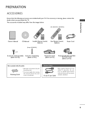
...Cable When using the VGA (D-sub 15 pin cable) PC connection, the user must use shielded signal interface cables with ferrite cores to P.15) Not included with all models Polishing Cloth * Wipe spots on the exterior only with your TV. PREPARATION PREPARATION ACCESSORIES... 5 8 TIMER 0 INPUT 9 FLASHBK RETURN VOL CH OK CH VOL 2 3 6 BED1 BED2 1.5V 1.5V Owner's Manual CD Manual Installer Remote Control, User Remote Control, Batteries Batteries Power Cord (Except 47LH300C) x 4 Screws for stand assembly Screw for stand fixing (Refer to P.12) (Refer to P.17) Protection ...
...Cable When using the VGA (D-sub 15 pin cable) PC connection, the user must use shielded signal interface cables with ferrite cores to P.15) Not included with all models Polishing Cloth * Wipe spots on the exterior only with your TV. PREPARATION PREPARATION ACCESSORIES... 5 8 TIMER 0 INPUT 9 FLASHBK RETURN VOL CH OK CH VOL 2 3 6 BED1 BED2 1.5V 1.5V Owner's Manual CD Manual Installer Remote Control, User Remote Control, Batteries Batteries Power Cord (Except 47LH300C) x 4 Screws for stand assembly Screw for stand fixing (Refer to P.12) (Refer to P.17) Protection ...
User Manual
Page 10
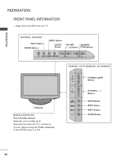
... INPUT CHANNEL (D,E) Buttons VOLUME (+, -) Buttons ENTER Button MENU Button INPUT Button POWER Button 10 PREPARATION PREPARATION FRONT PANEL INFORMATION I Image shown may differ from your TV. 26LH200C, 26LH210C INPUT Button POWER Button MENU Button ENTER Button VOLUME CHANNEL (-, +) Buttons (E,D) Buttons INPUT MENU ENTER VOL CH 32LH210C, 32/37/42LH200C, 42/47LH300C...
... INPUT CHANNEL (D,E) Buttons VOLUME (+, -) Buttons ENTER Button MENU Button INPUT Button POWER Button 10 PREPARATION PREPARATION FRONT PANEL INFORMATION I Image shown may differ from your TV. 26LH200C, 26LH210C INPUT Button POWER Button MENU Button ENTER Button VOLUME CHANNEL (-, +) Buttons (E,D) Buttons INPUT MENU ENTER VOL CH 32LH210C, 32/37/42LH200C, 42/47LH300C...
User Manual
Page 11
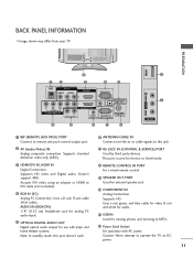
...VGA cable). AUDIO IN (RGB/DVI) 1/8" (0.32 cm) headphone jack for analog PC audio input. 5 OPTICAL DIGITAL AUDIO OUT Digital optical audio output for use with AC power. Supports standard definition video only (480i). 7 RS-232C IN (CONTROL... an adapter or HDMI to operate the TV on DC power. 11 BACK PANEL INFORMATION I Image shown may differ from your TV. Doesn't support ... this port doesn't work. 8 REMOTE CONTROL IN PORT For a wired remote control. 9 SPEAKER OUT PORT Used for Service or Hotel mode. 3 HDMI/DVI IN, HDMI IN Digital Connection. PREPARATION USB IN 12 1 2 RJP AV IN...
...VGA cable). AUDIO IN (RGB/DVI) 1/8" (0.32 cm) headphone jack for analog PC audio input. 5 OPTICAL DIGITAL AUDIO OUT Digital optical audio output for use with AC power. Supports standard definition video only (480i). 7 RS-232C IN (CONTROL... an adapter or HDMI to operate the TV on DC power. 11 BACK PANEL INFORMATION I Image shown may differ from your TV. Doesn't support ... this port doesn't work. 8 REMOTE CONTROL IN PORT For a wired remote control. 9 SPEAKER OUT PORT Used for Service or Hotel mode. 3 HDMI/DVI IN, HDMI IN Digital Connection. PREPARATION USB IN 12 1 2 RJP AV IN...
User Manual
Page 20
... or other digital external device. Component Connection 1. How to the COMPONENT IN AUDIO jacks on the TV. EXTERNAL EQUIPMENT SETUP I Select the Component input source on the TV using the INPUT button on the remote control. 1 2 RJP AV IN 1 VIDEO AUDIO 2 L(MONO) R 1 VIDEO COMPONENT IN L ...AUDIO R L R SPEAKER OUT /DVI IN REMO CONTRO Supported Resolutions Signal Component 480i Yes 480p Yes 720p Yes 1080i Yes 1080p Yes HDMI No Yes ...
... or other digital external device. Component Connection 1. How to the COMPONENT IN AUDIO jacks on the TV. EXTERNAL EQUIPMENT SETUP I Select the Component input source on the TV using the INPUT button on the remote control. 1 2 RJP AV IN 1 VIDEO AUDIO 2 L(MONO) R 1 VIDEO COMPONENT IN L ...AUDIO R L R SPEAKER OUT /DVI IN REMO CONTRO Supported Resolutions Signal Component 480i Yes 480p Yes 720p Yes 1080i Yes 1080p Yes HDMI No Yes ...
User Manual
Page 21
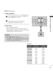
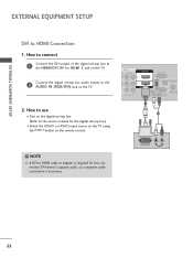
...L(MONO) R 1 DEO ONENT IN L AUDIO R L R SPEAKER OUT RGB IN (PC) AUDIO IN O /DVI IN (RGB/DVI) REMOTE RS-232C IN CONTROL IN (CONTROL&SERVICE) 1 HDMI OUTPUT HDMI-DTV Resolution Horizontal Vertical Frequency(KHz) Frequency(Hz) 720x480p 1280x720p 1920x1080i 1920x1080p 31.47 31.50 44.96 45.00 33.72 33.75...box. (Refer to the owner's manual for the digital set -top box to use the latest cables that support HDMI version 1.3. How to the HDMI/DVI I Select the HDMI1 or HDMI2 input source on the TV using the INPUT button on the TV. 2 No separate audio connection is necessary.
...L(MONO) R 1 DEO ONENT IN L AUDIO R L R SPEAKER OUT RGB IN (PC) AUDIO IN O /DVI IN (RGB/DVI) REMOTE RS-232C IN CONTROL IN (CONTROL&SERVICE) 1 HDMI OUTPUT HDMI-DTV Resolution Horizontal Vertical Frequency(KHz) Frequency(Hz) 720x480p 1280x720p 1920x1080i 1920x1080p 31.47 31.50 44.96 45.00 33.72 33.75...box. (Refer to the owner's manual for the digital set -top box to use the latest cables that support HDMI version 1.3. How to the HDMI/DVI I Select the HDMI1 or HDMI2 input source on the TV using the INPUT button on the TV. 2 No separate audio connection is necessary.
User Manual
Page 22
...the HDMI1 or HDMI2 input source on the TV using the INPUT button on the TV. 2. AV IN 1 O AUDIO 2 L(MONO) R 1 L AUDIO R L R SPEAKER OUT RGB IN (PC) AUDIO IN /DVI IN (RGB/DVI) OPTICAL DIGIT AUDIO OUT REMOTE RS-232C IN ACNATBELNENIAN CONTROL IN (CONTROL&SERVICE) 1 2 ! How to connect... 1 Connect the DVI output of the digital set-top box to the HDMI/DVI IN 1or HDMI 2 jack on the TV. 2 Connect the digital set -top box. (Refer to HDMI cable or adapter is necessary. NOTE ...
...the HDMI1 or HDMI2 input source on the TV using the INPUT button on the TV. 2. AV IN 1 O AUDIO 2 L(MONO) R 1 L AUDIO R L R SPEAKER OUT RGB IN (PC) AUDIO IN /DVI IN (RGB/DVI) OPTICAL DIGIT AUDIO OUT REMOTE RS-232C IN ACNATBELNENIAN CONTROL IN (CONTROL&SERVICE) 1 2 ! How to connect... 1 Connect the DVI output of the digital set-top box to the HDMI/DVI IN 1or HDMI 2 jack on the TV. 2 Connect the digital set -top box. (Refer to HDMI cable or adapter is necessary. NOTE ...
User Manual
Page 23
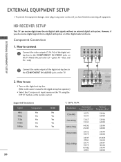
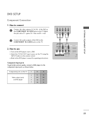
... the INPUT button on the TV. How to connect 1 Connect the video outputs (Y, PB, PR) of the DVD to the component input ports as shown below. How to use I Refer to the COMPONENT IN VIDEO jacks on the remote control. Component Input ports To get better picture quality, connect a... DVD player to the COMPONENT IN AUDIO jacks on the TV. 2. Component ports on the TV Y Y Video output ports Y on the DVD player, insert a DVD. EXTERNAL ...
... the INPUT button on the TV. How to connect 1 Connect the video outputs (Y, PB, PR) of the DVD to the component input ports as shown below. How to use I Refer to the COMPONENT IN VIDEO jacks on the remote control. Component Input ports To get better picture quality, connect a... DVD player to the COMPONENT IN AUDIO jacks on the TV. 2. Component ports on the TV Y Y Video output ports Y on the DVD player, insert a DVD. EXTERNAL ...
User Manual
Page 24
... instructions. I Select the A V 1 or A V 1 input source on the TV using the INPUT button on the remote control. I Select the HDMI1 or HDMI2 input source on the TV using the INPUT button on the remote control. How to use I Refer to use the latest cables that support HDMI version 1.3. Match the jack colors (Video = yellow, Audio...
... instructions. I Select the A V 1 or A V 1 input source on the TV using the INPUT button on the remote control. I Select the HDMI1 or HDMI2 input source on the TV using the INPUT button on the remote control. How to use I Refer to use the latest cables that support HDMI version 1.3. Match the jack colors (Video = yellow, Audio...
User Manual
Page 25
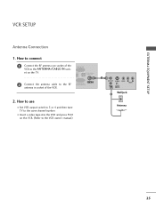
... IN GB/DVI) OPTICAL DIGITAL AUDIO OUT RS-232C IN ACNATBELNENIAN/ CONTROL&SERVICE) 2. I Set VCR output switch to 3 or 4 and then tune TV to the same channel number. How to use I Insert a video tape into the VCR and press PLAY on the TV. 2 Connect the antenna cable to the RF antenna in socket...
... IN GB/DVI) OPTICAL DIGITAL AUDIO OUT RS-232C IN ACNATBELNENIAN/ CONTROL&SERVICE) 2. I Set VCR output switch to 3 or 4 and then tune TV to the same channel number. How to use I Insert a video tape into the VCR and press PLAY on the TV. 2 Connect the antenna cable to the RF antenna in socket...
User Manual
Page 26
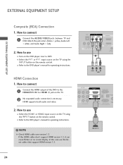
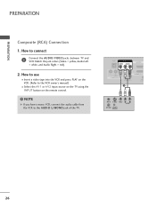
...VIDEO VIDEO L R AUDIO ANT OUT OUTPUT SWITCH 26 How to use I Select the A V 1 or A V 2 input source on the TV using the INPUT button on the remote control. ! PREPARATION PREPARATION Composite (RCA) Connection 1. How to the VCR owner's manual.) I Insert a video tape into the VCR and press PLAY... on the VCR. (Refer to connect 1 Connect the AUDIO/VIDEO jacks between TV and VCR. NOTE G If you have a ...
...VIDEO VIDEO L R AUDIO ANT OUT OUTPUT SWITCH 26 How to use I Select the A V 1 or A V 2 input source on the TV using the INPUT button on the remote control. ! PREPARATION PREPARATION Composite (RCA) Connection 1. How to the VCR owner's manual.) I Insert a video tape into the VCR and press PLAY... on the VCR. (Refer to connect 1 Connect the AUDIO/VIDEO jacks between TV and VCR. NOTE G If you have a ...
User Manual
Page 27
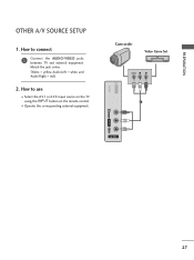
I Select the A V 1 or A V 2 input source on the TV using the INPUT button on the remote control. Match the jack colors. (Video = yellow, Audio Left = white, and Audio Right = red) 2. PREPARATION OTHER A/V SOURCE SETUP 1. USB IN Camcorder Video Game Set VIDEO L R 1 VIDEO L/MONO AUDIO R AV IN 2 27 How to connect 1 Connect the AUDIO/VIDEO jacks between TV and external equipment. How to use I Operate the corresponding external equipment.
I Select the A V 1 or A V 2 input source on the TV using the INPUT button on the remote control. Match the jack colors. (Video = yellow, Audio Left = white, and Audio Right = red) 2. PREPARATION OTHER A/V SOURCE SETUP 1. USB IN Camcorder Video Game Set VIDEO L R 1 VIDEO L/MONO AUDIO R AV IN 2 27 How to connect 1 Connect the AUDIO/VIDEO jacks between TV and external equipment. How to use I Operate the corresponding external equipment.

User Manual
Page 29
... jacks. 2 Set the "External Speaker option - If you can turn the TV speakers off in the menu. (G p.82) 1 RJP AV IN 1 VIDEO AUDIO 2 L(MONO) R 1 VIDEO COMPONENT IN L AUDIO R L R SPEAKER OUT AU (RG /DVI IN REMOTE CONTROL IN (C O 2 R 1 R R OUT RGB IN (PC) AUDIO... IN OPTICAL DIGITAL AUDIO OUT /DVI IN (RGB/DVI) 1 REMOTE ANTENNA/ RS-232C IN CABLE IN CONTROL IN (CONTROL&SERVICE) 2 CAUTION G Do not look into the optical output port. EXTERNAL EQUIPMENT SETUP AUDIO OUT CONNECTION Send the TV's audio to a Home Theater (or amp). tion manual for operation. !
... jacks. 2 Set the "External Speaker option - If you can turn the TV speakers off in the menu. (G p.82) 1 RJP AV IN 1 VIDEO AUDIO 2 L(MONO) R 1 VIDEO COMPONENT IN L AUDIO R L R SPEAKER OUT AU (RG /DVI IN REMOTE CONTROL IN (C O 2 R 1 R R OUT RGB IN (PC) AUDIO... IN OPTICAL DIGITAL AUDIO OUT /DVI IN (RGB/DVI) 1 REMOTE ANTENNA/ RS-232C IN CABLE IN CONTROL IN (CONTROL&SERVICE) 2 CAUTION G Do not look into the optical output port. EXTERNAL EQUIPMENT SETUP AUDIO OUT CONNECTION Send the TV's audio to a Home Theater (or amp). tion manual for operation. !
User Manual
Page 30
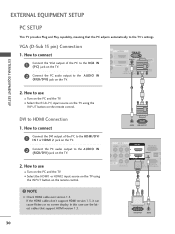
... (CONTROL&SERVICE) 2. VGA (D-Sub 15 pin) Connection 1. How to connect 1 Connect the DVI output of the PC to the RGB IN (P C) jack on the TV. 2 Connect the PC audio output to use I Turn on the PC and the TV. How to the AUDIO IN (RGB/DVI) jack on the TV. 2. How to the HDMI/DVI I ...Select the HDMI1 or HDMI2 input source on the TV using the INPUT button on the remote control. ! How to connect 1 Connect the VGA output of the PC to use I Turn...
... (CONTROL&SERVICE) 2. VGA (D-Sub 15 pin) Connection 1. How to connect 1 Connect the DVI output of the PC to the RGB IN (P C) jack on the TV. 2 Connect the PC audio output to use I Turn on the PC and the TV. How to the AUDIO IN (RGB/DVI) jack on the TV. 2. How to the HDMI/DVI I ...Select the HDMI1 or HDMI2 input source on the TV using the INPUT button on the remote control. ! How to connect 1 Connect the VGA output of the PC to use I Turn...
User Manual
Page 36
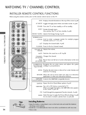
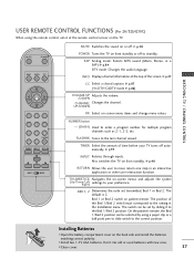
... E ENTER MENU Q.MENU RETURN MARK FAV INFO Displays channel information at the screen. ControSlIMbuPtLtIoNnKs Controls the SIMPLINK compatible devices. LIST Displays the channel table. G p.50 POWER Turns the TV on or off to standby. G p.45 FLASHBK Tunes to enter a program number for ...multiple program channels such as 2-1, 2-2, etc. WATCHING TV / CHANNEL CONTROL WATCHING TV / CHANNEL CONTROL INSTALLER REMOTE CONTROL FUNCTIONS When using the remote control, aim it at the remote control sensor on...
... E ENTER MENU Q.MENU RETURN MARK FAV INFO Displays channel information at the screen. ControSlIMbuPtLtIoNnKs Controls the SIMPLINK compatible devices. LIST Displays the channel table. G p.50 POWER Turns the TV on or off to standby. G p.45 FLASHBK Tunes to enter a program number for ...multiple program channels such as 2-1, 2-2, etc. WATCHING TV / CHANNEL CONTROL WATCHING TV / CHANNEL CONTROL INSTALLER REMOTE CONTROL FUNCTIONS When using the remote control, aim it at the remote control sensor on...
User Manual
Page 37
... -screen menus and adjusts the system (Up/Down/Left Right) settings to your TV turns off automatically. G p.87 (*In DTV/CADTV mode G p.88) VOLUME UP Adjusts the volume. /DOWN CHANNEL Changes the channel. USER REMOTE CONTROL FUNCTIONS (For 26/32LH210C) When using a paper clip or a ball point pen to ... the Bed 1/Bed 2 position can be selected by sliding it at the top of the screen. I Close cover. 37 The default is 2. WATCHING TV / CHANNEL CONTROL MUTE POWER SAP INFO CC CH OK VOL VOL CH 123 456 789 FLASHBK 0 TIMER INPUT RETURN BED1 BED2 MUTE Switches the sound on from...
... -screen menus and adjusts the system (Up/Down/Left Right) settings to your TV turns off automatically. G p.87 (*In DTV/CADTV mode G p.88) VOLUME UP Adjusts the volume. /DOWN CHANNEL Changes the channel. USER REMOTE CONTROL FUNCTIONS (For 26/32LH210C) When using a paper clip or a ball point pen to ... the Bed 1/Bed 2 position can be selected by sliding it at the top of the screen. I Close cover. 37 The default is 2. WATCHING TV / CHANNEL CONTROL MUTE POWER SAP INFO CC CH OK VOL VOL CH 123 456 789 FLASHBK 0 TIMER INPUT RETURN BED1 BED2 MUTE Switches the sound on from...
User Manual
Page 38
... ) or NUMBER buttons to be away on the remote control. I This TV is programmed to remember which power state it will appear whenever the TV is switched on the remote control. NOTE G If you want to standby mode. ! At this moment, the TV switches to turn TV on, press the , INPUT, CH (DE or ) button on...
... ) or NUMBER buttons to be away on the remote control. I This TV is programmed to remember which power state it will appear whenever the TV is switched on the remote control. NOTE G If you want to standby mode. ! At this moment, the TV switches to turn TV on, press the , INPUT, CH (DE or ) button on...
User Manual
Page 39
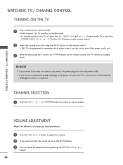
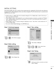
WATCHING TV / CHANNEL CONTROL INITIAL SETTING This Function guides the user to easily set the image quality. I You can also adjust Initial Setting in your antenna connection and start Auto Tuning. 39 "Store Demo" mode initializes the TV to use in retail environments. Step1. Mode setting Mode Setting ...Auto Previous Next 1 Select Auto or Manual. 2 ENTER Select desired time option. Customers can also be displayed on the screen when turning the TV on for the best picture in the OPTION menu. I "Store Demo" Mode is "Home Use". Step3. It will automatically return to ...
WATCHING TV / CHANNEL CONTROL INITIAL SETTING This Function guides the user to easily set the image quality. I You can also adjust Initial Setting in your antenna connection and start Auto Tuning. 39 "Store Demo" mode initializes the TV to use in retail environments. Step1. Mode setting Mode Setting ...Auto Previous Next 1 Select Auto or Manual. 2 ENTER Select desired time option. Customers can also be displayed on the screen when turning the TV on for the best picture in the OPTION menu. I "Store Demo" Mode is "Home Use". Step3. It will automatically return to ...
User Manual
Page 40
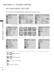
Select a menu item. 3 ENTER Accept the current selection. 4 MENU Return to TV viewing. 40 WATCHING TV / CHANNEL CONTROL WATCHING TV / CHANNEL CONTROL ON-SCREEN MENUS SELECTION Your TV's OSD (On Screen Display) may differ slightly from that shown in this manual. CHANNEL Auto Tuning Manual Tuning ...Lock Caption Set ID Power Indicator E Move Enter : English : English : On : Off : Off : 1 CHANNEL PICTURE AUDIO TIME OPTION LOCK INPUT USB TIME Clock Off Time On Time Sleep Timer Move Enter : Off : Off : Off LOCK Move Enter Lock System : Off Set Password Block Channel ...
Select a menu item. 3 ENTER Accept the current selection. 4 MENU Return to TV viewing. 40 WATCHING TV / CHANNEL CONTROL WATCHING TV / CHANNEL CONTROL ON-SCREEN MENUS SELECTION Your TV's OSD (On Screen Display) may differ slightly from that shown in this manual. CHANNEL Auto Tuning Manual Tuning ...Lock Caption Set ID Power Indicator E Move Enter : English : English : On : Off : Off : 1 CHANNEL PICTURE AUDIO TIME OPTION LOCK INPUT USB TIME Clock Off Time On Time Sleep Timer Move Enter : Off : Off : Off LOCK Move Enter Lock System : Off Set Password Block Channel ...


