

Owner's Manual
Page 1
ENGLISH LCD TV PLASMA TV OWNER'S MANUAL LCD TV MODELS PLASMA TV MODELS 26LC4R* 26LC7R* 32LC4R* 32LC7R* 37LC4R* 37LC7R* 42LC4R* 42LC7R* 32LB9R* 42LB9R* 42PC5R* 42PC5RV* 42PC7R* 50PC5R* Please read this information. Retain it for future reference. Record model number and serial number of the set . To your set . Refer to the label on the back cover and quote this manual carefully before operating your dealer when requiring service.
ENGLISH LCD TV PLASMA TV OWNER'S MANUAL LCD TV MODELS PLASMA TV MODELS 26LC4R* 26LC7R* 32LC4R* 32LC7R* 37LC4R* 37LC7R* 42LC4R* 42LC7R* 32LB9R* 42LB9R* 42PC5R* 42PC5RV* 42PC7R* 50PC5R* Please read this information. Retain it for future reference. Record model number and serial number of the set . To your set . Refer to the label on the back cover and quote this manual carefully before operating your dealer when requiring service.
Owner's Manual
Page 3
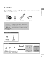
... INDEX Remote Control Power Cord *Lightly wipe any stains or fingerprints on the screen This feature is not available for all models. Plasma TV models 2-Wall brackets This feature is not available for all models. 2-eye-bolts This feature is not available for all models. for...+ INPUTTINVPUT POWER DVD TEXT STB TMVODE Q.VIEW SLEEP PIP I /II INPUT OK SLEEP FAV PR 7 5 3 TIME 8 6 SIZE 0 9 REVEAL ? LCD TV models 26", 32", 37" only 32LB9R* only or 2- Polishing Cloth Polishing cloth for use excessive force. Arrange the wires with the twister holder. If an...
... INDEX Remote Control Power Cord *Lightly wipe any stains or fingerprints on the screen This feature is not available for all models. Plasma TV models 2-Wall brackets This feature is not available for all models. 2-eye-bolts This feature is not available for all models. for...+ INPUTTINVPUT POWER DVD TEXT STB TMVODE Q.VIEW SLEEP PIP I /II INPUT OK SLEEP FAV PR 7 5 3 TIME 8 6 SIZE 0 9 REVEAL ? LCD TV models 26", 32", 37" only 32LB9R* only or 2- Polishing Cloth Polishing cloth for use excessive force. Arrange the wires with the twister holder. If an...
Owner's Manual
Page 4
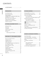
...59 Low-Power Picture Mode 60 SOUND & LANGUAGE CONTROL Auto Volume Leveler 61 Preset Sound Settings - User Mode 63 Balance 64 TV Speakers On/Off Setup 65 I/II - User Option 53 - Cinema 56 Advanced - NICAM Reception 67 - CONTENTS CONTENTS ACCESSORIES ...1 PREPARATION Front Panel Controls 4 Back Panel Information 6 Stand Installation 8 ATTACHING THE TV TO A DESK (Only 32LB9R* model) ........ 8 Attaching the TV to a Wall 9 Back Cover for PC Mode 28 WATCHIINNGGTTVV//PROGRAMMMMEECCOONNTTRROOLL Remote Control Key Functions 32 Turning on the...
...59 Low-Power Picture Mode 60 SOUND & LANGUAGE CONTROL Auto Volume Leveler 61 Preset Sound Settings - User Mode 63 Balance 64 TV Speakers On/Off Setup 65 I/II - User Option 53 - Cinema 56 Advanced - NICAM Reception 67 - CONTENTS CONTENTS ACCESSORIES ...1 PREPARATION Front Panel Controls 4 Back Panel Information 6 Stand Installation 8 ATTACHING THE TV TO A DESK (Only 32LB9R* model) ........ 8 Attaching the TV to a Wall 9 Back Cover for PC Mode 28 WATCHIINNGGTTVV//PROGRAMMMMEECCOONNTTRROOLL Remote Control Key Functions 32 Turning on the...
Owner's Manual
Page 6
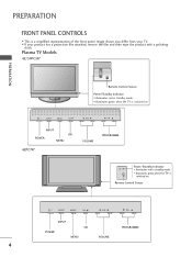
... VOL PR VOLUME PROGRAMME INPUT MENU OK VOL PR Power/Standby Indicator • illuminates red in standby mode. Image shown may differ from your TV. ■ If your product has a protection film attached, remove the film and then wipe the product with a polishing cloth. INPUT MENU ...INPUT INPUT MENU POWER MENU OK OK VOL PR VOLUME PROGRAMME 4 PREPARATION FRONT PANEL CONTROLS ■ This is switched on . Plasma TV Models 42/50PC5R* PREPARATION Remote Control Sensor Power/Standby Indicator • illuminates red in standby mode. • illuminates green when the...
... VOL PR VOLUME PROGRAMME INPUT MENU OK VOL PR Power/Standby Indicator • illuminates red in standby mode. Image shown may differ from your TV. ■ If your product has a protection film attached, remove the film and then wipe the product with a polishing cloth. INPUT MENU ...INPUT INPUT MENU POWER MENU OK OK VOL PR VOLUME PROGRAMME 4 PREPARATION FRONT PANEL CONTROLS ■ This is switched on . Plasma TV Models 42/50PC5R* PREPARATION Remote Control Sensor Power/Standby Indicator • illuminates red in standby mode. • illuminates green when the...
Owner's Manual
Page 7
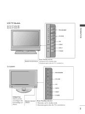
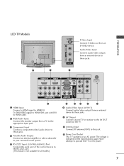
PREPARATION LCD TV Models 26/32/37/42LC4R* 26/32/37/42LC7R* PR VOL OK MENU INPUT /I OK MENU INPUT Intelligent Eye Adjusts picture according to the surrounding conditions. PROGRAMME PR VOL VOLUME OK MENU INPUT /I PROGRAMME VOLUME OK MENU INPUT POWER 32/42LB9R* Power/Standby Indicator Remote Control Sensor • illuminates red in standby mode. • illuminates green when the TV is switched on . 5 POWER Remote Control Power/Standby Indicator Sensor • illuminates red in standby mode. • illuminates green when the TV is switched on .
PREPARATION LCD TV Models 26/32/37/42LC4R* 26/32/37/42LC7R* PR VOL OK MENU INPUT /I OK MENU INPUT Intelligent Eye Adjusts picture according to the surrounding conditions. PROGRAMME PR VOL VOLUME OK MENU INPUT /I PROGRAMME VOLUME OK MENU INPUT POWER 32/42LB9R* Power/Standby Indicator Remote Control Sensor • illuminates red in standby mode. • illuminates green when the TV is switched on . 5 POWER Remote Control Power/Standby Indicator Sensor • illuminates red in standby mode. • illuminates green when the TV is switched on .
Owner's Manual
Page 9
...VIDEO VARIABLE AUDIO AOVUITN 2 AV IN 2 2 S-Video Input AVCINo1nnAeVctOSUT-Video out from an external device to this jack. 9 Power Cord Socket This TV operates on the Specifications page. RS-232C IN (CONTROL & SERVICE) R AUDIO L/MONO VIDEO 4 Variable Audio Output Connect an external amplifier or ...AV IN 1 AV OUT RS-232C IN (CONTROL & SERVICE) R AUDIO L/MONO VIDEO VARIABLE 3 A1UDHIOD1OMUITInput Co2nnect a HDMI signal to operate the TV on DC power. 7 Audio/Video Input Connect audio/video output from an S-VIDEO device. Or DVI(CVOMIDPONEEONT I)Nsignal to HDMI/DVI VARIABLE AUDIO ...
...VIDEO VARIABLE AUDIO AOVUITN 2 AV IN 2 2 S-Video Input AVCINo1nnAeVctOSUT-Video out from an external device to this jack. 9 Power Cord Socket This TV operates on the Specifications page. RS-232C IN (CONTROL & SERVICE) R AUDIO L/MONO VIDEO 4 Variable Audio Output Connect an external amplifier or ...AV IN 1 AV OUT RS-232C IN (CONTROL & SERVICE) R AUDIO L/MONO VIDEO VARIABLE 3 A1UDHIOD1OMUITInput Co2nnect a HDMI signal to operate the TV on DC power. 7 Audio/Video Input Connect audio/video output from an S-VIDEO device. Or DVI(CVOMIDPONEEONT I)Nsignal to HDMI/DVI VARIABLE AUDIO ...
Owner's Manual
Page 10
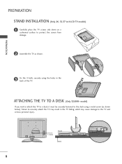
...screw (as shown. Failure to securely attach the TV may cause damage to the TV and serious personal injury. 1-Screw Stand Desk 8 which may result in the back of the TV. ATTACHING THE TV TO A DESK (Only 32LB9R* model) If you wish to attach the TV to a desk, it must be securely fastened to... the desk using the holes in the TV falling; PREPARATION STAND INSTALLATION (Only 26, 32,37 inch LCD TV models) 1 Carefully place the TV screen side down on a cushioned surface to protect the screen...
...screw (as shown. Failure to securely attach the TV may cause damage to the TV and serious personal injury. 1-Screw Stand Desk 8 which may result in the back of the TV. ATTACHING THE TV TO A DESK (Only 32LB9R* model) If you wish to attach the TV to a desk, it must be securely fastened to... the desk using the holes in the TV falling; PREPARATION STAND INSTALLATION (Only 26, 32,37 inch LCD TV models) 1 Carefully place the TV screen side down on a cushioned surface to protect the screen...

Owner's Manual
Page 11
... shown below are even. 3 3 Use a strong cord (must purchase seperately) to the wall. PREPARATION ATTACHING THE TV TO A WALL (This feature is not available for all models.) ■ Position the TV close to the wall to avoid the possibility of it falling forwards if pulled. This will prevent the... TV from damage. Plasma TV models LCD TV models 1 1 2 2 1 Use the eye-bolts or TV brackets/bolts to fix the product to support the...
... shown below are even. 3 3 Use a strong cord (must purchase seperately) to the wall. PREPARATION ATTACHING THE TV TO A WALL (This feature is not available for all models.) ■ Position the TV close to the wall to avoid the possibility of it falling forwards if pulled. This will prevent the... TV from damage. Plasma TV models LCD TV models 1 1 2 2 1 Use the eye-bolts or TV brackets/bolts to fix the product to support the...
Owner's Manual
Page 12
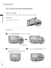
CABLE MANAGEMENT 2 Connect the cables as shown. 10 To connect additional equipment, see the External equipment Setup section of the manual. 3 Reinstall the CABLE MANAGEMENT as necessary. Stand type 1 Arrange the cables as shown picture. Stand type 2 1 Grip the CABLE MANAGEMENT and push the cover upwards. PREPARATION PREPARATION BACK COVER FOR WIRE ARRANGEMENT Plasma TV models ■ These models have two cable arrangement methods according to the stand type.
CABLE MANAGEMENT 2 Connect the cables as shown. 10 To connect additional equipment, see the External equipment Setup section of the manual. 3 Reinstall the CABLE MANAGEMENT as necessary. Stand type 1 Arrange the cables as shown picture. Stand type 2 1 Grip the CABLE MANAGEMENT and push the cover upwards. PREPARATION PREPARATION BACK COVER FOR WIRE ARRANGEMENT Plasma TV models ■ These models have two cable arrangement methods according to the stand type.
Owner's Manual
Page 13
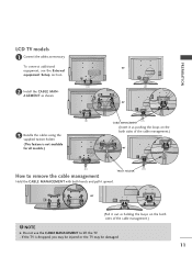
...out as shown. 3 Bundle the cables using the supplied twister holder. (This feature is dropped, you may be injured or the TV may be damaged. 11 If the TV is not available for all models.) or or CABLE MANAGEMENT (Insert it upward. To connect additional equipment, see the External equipment ...section. 2 Install the CABLE MANAGEMENT as holding the loops on the both sides of the cable management.) or TWIST HOLDER How to lift the TV. - PREPARATION LCD TV models 1 Connect the cables as pushing the loops on the both sides of the cable management.) ! NOTE G Do not use the CABLE ...
...out as shown. 3 Bundle the cables using the supplied twister holder. (This feature is dropped, you may be injured or the TV may be damaged. 11 If the TV is not available for all models.) or or CABLE MANAGEMENT (Insert it upward. To connect additional equipment, see the External equipment ...section. 2 Install the CABLE MANAGEMENT as holding the loops on the both sides of the cable management.) or TWIST HOLDER How to lift the TV. - PREPARATION LCD TV models 1 Connect the cables as pushing the loops on the both sides of the cable management.) ! NOTE G Do not use the CABLE ...
Owner's Manual
Page 14
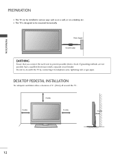
... PEDESTAL INSTALLATION For adequate ventilation allow a clearance of 4" (10cm) all around the TV . 4 inches 4 inches 4 inches 4 inches 12 PREPARATION PREPARATION ■ The TV can be installed in various ways such as on a wall, or on a desktop etc. ■ The TV is designed to prevent possible electric shock. If grounding methods are not possible...a separate circuit breaker. Power Supply Circuit breaker EARTHING Ensure that you connect the earth wire to be mounted horizontally. Do not try to earth the TV by connecting it to telephone wires, lightening rods or gas pipes.
... PEDESTAL INSTALLATION For adequate ventilation allow a clearance of 4" (10cm) all around the TV . 4 inches 4 inches 4 inches 4 inches 12 PREPARATION PREPARATION ■ The TV can be installed in various ways such as on a wall, or on a desktop etc. ■ The TV is designed to prevent possible electric shock. If grounding methods are not possible...a separate circuit breaker. Power Supply Circuit breaker EARTHING Ensure that you connect the earth wire to be mounted horizontally. Do not try to earth the TV by connecting it to telephone wires, lightening rods or gas pipes.

Owner's Manual
Page 15
Detailed installation instruc-tions are available from your dealer, see the optional Tilt Wall Mounting Bracket Installation and Setup Guide. PREPARATION 4 inches 4 inches 4 inches 4 inches 4 inches 13 WALL MOUNT: HORIZONTAL INSTALLATION For adequate ventilation allow a clearance of 4" (10cm) all around the TV.
Detailed installation instruc-tions are available from your dealer, see the optional Tilt Wall Mounting Bracket Installation and Setup Guide. PREPARATION 4 inches 4 inches 4 inches 4 inches 4 inches 13 WALL MOUNT: HORIZONTAL INSTALLATION For adequate ventilation allow a clearance of 4" (10cm) all around the TV.

Owner's Manual
Page 16
... cable and converter are made between the devices. PREPARATION PREPARATION ■ It is recommended that 42PC5RH / 42PC5RVH / 50PC5RH / 42PC7RVH model only be split for two TVs, use an antenna signal splitter for connection. 14 HDMI/DVI IN 1 HDMI IN 2 RGB IN AV IN 1 AV OUT RS-232C IN (CONTROL & SERVICE) R AUDIO...
... cable and converter are made between the devices. PREPARATION PREPARATION ■ It is recommended that 42PC5RH / 42PC5RVH / 50PC5RH / 42PC7RVH model only be split for two TVs, use an antenna signal splitter for connection. 14 HDMI/DVI IN 1 HDMI IN 2 RGB IN AV IN 1 AV OUT RS-232C IN (CONTROL & SERVICE) R AUDIO...
Owner's Manual
Page 17
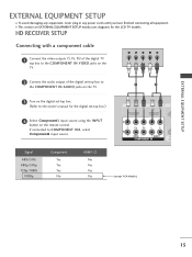
...-top box.) HDMI DVI IN HDMI IN 4 Select Component1 input source using the INPUT button on EXTERNAL EQUIPMENT SETUP mainly uses diagrams for the LCD TV models. HD RECEIVER SETUP Connecting with a component cable 1 Connect the video outputs (Y, PB, PR) of the digital... TV top box to the COMPONENT IN VIDEO jacks on the TV. 2 Connect the audio output of the digital set-top box to the COMPONENT IN AUDIO jacks on the TV. 1 2 3 Turn on the digital set-top box. (Refer to COMPONENT IN2...
...-top box.) HDMI DVI IN HDMI IN 4 Select Component1 input source using the INPUT button on EXTERNAL EQUIPMENT SETUP mainly uses diagrams for the LCD TV models. HD RECEIVER SETUP Connecting with a component cable 1 Connect the video outputs (Y, PB, PR) of the digital... TV top box to the COMPONENT IN VIDEO jacks on the TV. 2 Connect the audio output of the digital set-top box to the COMPONENT IN AUDIO jacks on the TV. 1 2 3 Turn on the digital set-top box. (Refer to COMPONENT IN2...
Owner's Manual
Page 18
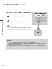
To get the best picture quality, adjust the output resolution of the source device will be automatically TV to 1280x720p. G If the digital set -top box.) HHDDMMI DI/DVVI ININ 1 HHDDMMII IINN 2 1 ! EXTERNAL EQUIPMENT SETUP EXTERNAL EQUIPMENT SETUP 1 2 COMPONENT IN Connecting a ...set-top box with using the INPUT button on the remote control. 3 Turn on the TV. 2 Select HDMI1 or HDMI2 input source using a HDMI cable. NOTE G TV can receive the video and audio signal simultaneously with an HDMI cable 1 Connect the HDMI output of the digital set...
To get the best picture quality, adjust the output resolution of the source device will be automatically TV to 1280x720p. G If the digital set -top box.) HHDDMMI DI/DVVI ININ 1 HHDDMMII IINN 2 1 ! EXTERNAL EQUIPMENT SETUP EXTERNAL EQUIPMENT SETUP 1 2 COMPONENT IN Connecting a ...set-top box with using the INPUT button on the remote control. 3 Turn on the TV. 2 Select HDMI1 or HDMI2 input source using a HDMI cable. NOTE G TV can receive the video and audio signal simultaneously with an HDMI cable 1 Connect the HDMI output of the digital set...
Owner's Manual
Page 19
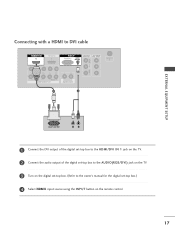
Connecting with a HDMI to DVI cable HHDDMMI DI/DVVI ININ 1 HDMI IN RGB IN RGB(PC) AUDIO (RGB/DVI) RGB(PC) AUDIO (RGB/DVI) AV IN 1 AV OUT L/MONO 1 2 EXTERNAL EQUIPMENT SETUP 1 Connect the DVI output of the digital set-top box to the HDMI/DVI IN 1 jack on the TV. 2 Connect the audio output of the digital set-top box to the AUDIO(RGB/DVI) jack on the TV. 3 Turn on the digital set-top box. (Refer to the owner's manual for the digital set-top box.) 4 Select HDMI1 input source using the INPUT button on the remote control. 17
Connecting with a HDMI to DVI cable HHDDMMI DI/DVVI ININ 1 HDMI IN RGB IN RGB(PC) AUDIO (RGB/DVI) RGB(PC) AUDIO (RGB/DVI) AV IN 1 AV OUT L/MONO 1 2 EXTERNAL EQUIPMENT SETUP 1 Connect the DVI output of the digital set-top box to the HDMI/DVI IN 1 jack on the TV. 2 Connect the audio output of the digital set-top box to the AUDIO(RGB/DVI) jack on the TV. 3 Turn on the digital set-top box. (Refer to the owner's manual for the digital set-top box.) 4 Select HDMI1 input source using the INPUT button on the remote control. 17
Owner's Manual
Page 20
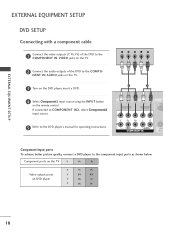
NENT IN AUDIO jacks on the TV. 3 Turn on the DVD player, insert a DVD. 1 2 4 Select Component1 input source using the INPUT button on DVD player Y PB PR Y B-Y ... cable 1 Connect the video outputs (Y, PB, PR) of the DVD to the COMPONENT IN VIDEO jacks on the TV. 2 Connect the audio outputs of the DVD to the component input ports as shown below. Component ports on the... TV Y PB PR Video output ports on the remote control. HDMI DVI IN HDMI IN RG If connected to COMPONENT IN2,...
NENT IN AUDIO jacks on the TV. 3 Turn on the DVD player, insert a DVD. 1 2 4 Select Component1 input source using the INPUT button on DVD player Y PB PR Y B-Y ... cable 1 Connect the video outputs (Y, PB, PR) of the DVD to the COMPONENT IN VIDEO jacks on the TV. 2 Connect the audio outputs of the DVD to the component input ports as shown below. Component ports on the... TV Y PB PR Video output ports on the remote control. HDMI DVI IN HDMI IN RG If connected to COMPONENT IN2,...
Owner's Manual
Page 21
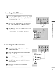
... 2IN input source. 1 AAVVIINN11 AV OUT EXTERNAL EQUIPMENT SETUP L/MONO R AUDIO L/MONO VIDEO Connecting with a RCA cable 1 Connect the AUDIO/VIDEO jacks between TV and DVD player. VIDEO L/MONO AUDIO R AV IN 2 Connecting with a S-Video cable 1 Connect the S-VIDEO output of the DVD to the AUDIO input... jacks on the TV. 3 Turn on the DVD player, insert a DVD. 4 Select AV2 input source using the INPUT button on the remote control. 5 Refer to the DVD ...
... 2IN input source. 1 AAVVIINN11 AV OUT EXTERNAL EQUIPMENT SETUP L/MONO R AUDIO L/MONO VIDEO Connecting with a RCA cable 1 Connect the AUDIO/VIDEO jacks between TV and DVD player. VIDEO L/MONO AUDIO R AV IN 2 Connecting with a S-Video cable 1 Connect the S-VIDEO output of the DVD to the AUDIO input... jacks on the TV. 3 Turn on the DVD player, insert a DVD. 4 Select AV2 input source using the INPUT button on the remote control. 5 Refer to the DVD ...
Owner's Manual
Page 22
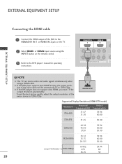
... 60 50 20 G If the DVD player does not support Auto HDMI, you must TV the output resolution appropriately. NOTE G The TV can receive video and audio signals simultaneously when using the INPUT button on the TV. 2 Select HDMI1 or HDMI2 input source using a HDMI cable. EXTERNAL EQUIPMENT SETUP 1... the remote control. G If the DVD player supports Auto HDMI function, the output resolution of the source device will be automatically TV to 1280x720p. HHDDMMI DI/DVVI ININ 1 HHDDMMII IINN 2 EXTERNAL EQUIPMENT SETUP 3 Refer to the DVD player's manual for operating instructions. 1 !
... 60 50 20 G If the DVD player does not support Auto HDMI, you must TV the output resolution appropriately. NOTE G The TV can receive video and audio signals simultaneously when using the INPUT button on the TV. 2 Select HDMI1 or HDMI2 input source using a HDMI cable. EXTERNAL EQUIPMENT SETUP 1... the remote control. G If the DVD player supports Auto HDMI function, the output resolution of the source device will be automatically TV to 1280x720p. HHDDMMI DI/DVVI ININ 1 HHDDMMII IINN 2 EXTERNAL EQUIPMENT SETUP 3 Refer to the DVD player's manual for operating instructions. 1 !
Owner's Manual
Page 23
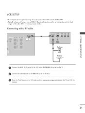
... OUT S-VIDEO VIDEO L R 1 ANT IN OUTPUT SWITCH Wall Jack 2 Antenna 1 Connect the ANT OUT socket of the VCR to the ANTENNA IN socket on the TV. 2 Connect the antenna cable to the ANT IN socket of the VCR. 3 Press the PLAY button on the sides of the screen may remain visible... DVI IN HDMI IN 21 L/MONO VIDEO L/MONO AUDIO R EXTERNAL EQUIPMENT SETUP VCR SETUP ■ To avoid picture noise (interference), allow adequate distance between the TV and VCR for an extended period the fixed images on the VCR and match the appropriate programme between the VCR and...
... OUT S-VIDEO VIDEO L R 1 ANT IN OUTPUT SWITCH Wall Jack 2 Antenna 1 Connect the ANT OUT socket of the VCR to the ANTENNA IN socket on the TV. 2 Connect the antenna cable to the ANT IN socket of the VCR. 3 Press the PLAY button on the sides of the screen may remain visible... DVI IN HDMI IN 21 L/MONO VIDEO L/MONO AUDIO R EXTERNAL EQUIPMENT SETUP VCR SETUP ■ To avoid picture noise (interference), allow adequate distance between the TV and VCR for an extended period the fixed images on the VCR and match the appropriate programme between the VCR and...


