Owners Manual
Page 5
C 0 Bt e n | s 2 3~4 7 8~11 Warning Safety instructions Accessories Controls Connection Options 12~13 Remote Control Key Functions i!!!liilii/llli/ilil!!i 14 15 16-17 18 19-20 20 21-22 23-24 25 25 26-28 Attaching the TV to a wall Desktop Pedestal Installation Basic Connection Antenna or Cable Connection VCR Setup External AV Source ...Setup Digital Audio Output PC Setup 29 29 29 29 30 31 31 32 33 33 34 35 35_36 37 38 39 40 41 41 _42 43 43 Turning on the TV Volume Adjustment Channel Selection On Screen Menus Language Selection On Screen Menus Selection and Adjustment EZ Scan (Channel ...
C 0 Bt e n | s 2 3~4 7 8~11 Warning Safety instructions Accessories Controls Connection Options 12~13 Remote Control Key Functions i!!!liilii/llli/ilil!!i 14 15 16-17 18 19-20 20 21-22 23-24 25 25 26-28 Attaching the TV to a wall Desktop Pedestal Installation Basic Connection Antenna or Cable Connection VCR Setup External AV Source ...Setup Digital Audio Output PC Setup 29 29 29 29 30 31 31 32 33 33 34 35 35_36 37 38 39 40 41 41 _42 43 43 Turning on the TV Volume Adjustment Channel Selection On Screen Menus Language Selection On Screen Menus Selection and Adjustment EZ Scan (Channel ...
Owners Manual
Page 7
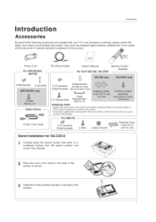
...cause scratch or discoloration. Power Cord For 42PC3D/3DV, 50PC3D 75D Round Cable Owner's Manual Remote Control / Batteries F..o..r....3..2../.3..7../.4..2..L..C...2..D..,......3..2..L..C..2..D...U....... ? 2-Wall brackets 2-eye-bolts Twister Holder 2-TV brackets Arrange the wires 2-Wall brackets with the cloth. th4eo,ts 3 product. ,othe...shielded signal interface cables(D-sub 15 pin cable) with your TV. D-sub 15 pin cable X F...o..r...60P01D 2-TV brackets 2-Wall brackets _ 4- O--p--ti-o--n Extras 2-TV Bracket Bolts Cable Management (Refer p.16) [Polishing Cloth] ...
...cause scratch or discoloration. Power Cord For 42PC3D/3DV, 50PC3D 75D Round Cable Owner's Manual Remote Control / Batteries F..o..r....3..2../.3..7../.4..2..L..C...2..D..,......3..2..L..C..2..D...U....... ? 2-Wall brackets 2-eye-bolts Twister Holder 2-TV brackets Arrange the wires 2-Wall brackets with the cloth. th4eo,ts 3 product. ,othe...shielded signal interface cables(D-sub 15 pin cable) with your TV. D-sub 15 pin cable X F...o..r...60P01D 2-TV brackets 2-Wall brackets _ 4- O--p--ti-o--n Extras 2-TV Bracket Bolts Cable Management (Refer p.16) [Polishing Cloth] ...

Owners Manual
Page 8
Illuminates white when the set is switched on . This is switched on . 60P01 D = CHANNEL (A, V') Buttons - This picture shown below may be somewhat different from your TV. 42PC3D/3DV, 50PC3D Remote Control Sensor Power/Standby Indicator ,, illuminates red in standby mode. Introduction Controls (Model Name: 42PC3D/3DV, 50PC3D, 60PC1D) - VOLUME (_,_) Buttons ENTER Button MENU Button INPUT Button (b/t (Power) Button I Remote Control Sensor Power Standby Indicator Illuminates red in standby mode. ,, illuminates green when the set is a simplified representation of front panel. -
Illuminates white when the set is switched on . This is switched on . 60P01 D = CHANNEL (A, V') Buttons - This picture shown below may be somewhat different from your TV. 42PC3D/3DV, 50PC3D Remote Control Sensor Power/Standby Indicator ,, illuminates red in standby mode. Introduction Controls (Model Name: 42PC3D/3DV, 50PC3D, 60PC1D) - VOLUME (_,_) Buttons ENTER Button MENU Button INPUT Button (b/t (Power) Button I Remote Control Sensor Power Standby Indicator Illuminates red in standby mode. ,, illuminates green when the set is a simplified representation of front panel. -
Owners Manual
Page 9
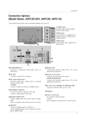
device to @AV OUT Connect a second TV or monitor. @AV (Audio/Video) IN 1 Connect audio/video device to stereo sound from your wired remote control. AUDIO Input Connections are available for listening to these jacks. VIDEO Input Connects the video signal from various types of equipment. Note: .... AUDIO IN (RGB/DVI) Connect the monitor output from an S-VIDEO device. @ANTENNA/CABLE IN Connect over-the air signals to the @ Remote Control Port Connect your TV. S-VIDEO output from an external Connect S-Video out from a PC to the appropriate input port. @RS-232C IN...
device to @AV OUT Connect a second TV or monitor. @AV (Audio/Video) IN 1 Connect audio/video device to stereo sound from your wired remote control. AUDIO Input Connections are available for listening to these jacks. VIDEO Input Connects the video signal from various types of equipment. Note: .... AUDIO IN (RGB/DVI) Connect the monitor output from an S-VIDEO device. @ANTENNA/CABLE IN Connect over-the air signals to the @ Remote Control Port Connect your TV. S-VIDEO output from an external Connect S-Video out from a PC to the appropriate input port. @RS-232C IN...

Owners Manual
Page 10
The TV can be somewhat different from your TV. Buttons (A, _) (_,_) Buttons -- ENTER Button Button -- This is switched on its stand 30 ° to the left or right to provide the optimum viewing angle. 10 This picture shown below may be conveniently swivelled on . Remote Control Sensor Power/Standby Indicator ,, illuminates red in standby mode. ,, illuminates green when the set is a simplified representation of front panel. - INPUT Button -- (b/l (Power) Button Swivel Stand (42:LC2D Only) - Introduction Controls (Model Name: 32/37/42LC2D, 32LC2DU) -
The TV can be somewhat different from your TV. Buttons (A, _) (_,_) Buttons -- ENTER Button Button -- This is switched on its stand 30 ° to the left or right to provide the optimum viewing angle. 10 This picture shown below may be conveniently swivelled on . Remote Control Sensor Power/Standby Indicator ,, illuminates red in standby mode. ,, illuminates green when the set is a simplified representation of front panel. - INPUT Button -- (b/l (Power) Button Swivel Stand (42:LC2D Only) - Introduction Controls (Model Name: 32/37/42LC2D, 32LC2DU) -
Owners Manual
Page 11
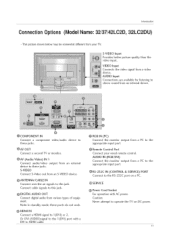
... signals to this jack. @ DIGITAL AUDIO OUT Connect digital audio from a PC to operate the TV on a PC. O Power Cord Socket For operation with a DVI to ] (DVl) or 2. Caution: Never attempt to the O Remote Control Port Connect your TV. device to @AV (Audio/Video) IN 1 Connect audio/video device to this jack. VIDEO Input.... AUDIO IN (RGB/DVl) Connect the monitor output appropriate input port. Connect cable signals to these jacks. Introduction Connecti on Opt"lon s (Model Name: 32/37/42LC2D, 32LC2DU) - from various types of equipment.
... signals to this jack. @ DIGITAL AUDIO OUT Connect digital audio from a PC to operate the TV on a PC. O Power Cord Socket For operation with a DVI to ] (DVl) or 2. Caution: Never attempt to the O Remote Control Port Connect your TV. device to @AV (Audio/Video) IN 1 Connect audio/video device to this jack. VIDEO Input.... AUDIO IN (RGB/DVl) Connect the monitor output appropriate input port. Connect cable signals to these jacks. Introduction Connecti on Opt"lon s (Model Name: 32/37/42LC2D, 32LC2DU) - from various types of equipment.
Owners Manual
Page 14
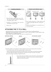
...holes in a forward direction, tially causing injury or damaging the product. poten- 42PC3D/3DV, 50PC3D 60PC1D 32/37/42LC2D, 32LC2DU _ Insert the eye-bolts (or TV brackets and bolts) to tighten the product to the wall as parts of the bracket that children don't ... over if pushed backwards. Introduction 32/37/42LC2D, 32LC2DU 42PC3D/3DV, 50PC3D ! Match the height of the product, must purchase separately) on the back side and instal[ the batteries matching correct polarity (+with +,-with new ones. _Close coveg _ Use a remote control 30 degree (left/right) scope.
...holes in a forward direction, tially causing injury or damaging the product. poten- 42PC3D/3DV, 50PC3D 60PC1D 32/37/42LC2D, 32LC2DU _ Insert the eye-bolts (or TV brackets and bolts) to tighten the product to the wall as parts of the bracket that children don't ... over if pushed backwards. Introduction 32/37/42LC2D, 32LC2DU 42PC3D/3DV, 50PC3D ! Match the height of the product, must purchase separately) on the back side and instal[ the batteries matching correct polarity (+with +,-with new ones. _Close coveg _ Use a remote control 30 degree (left/right) scope.
Owners Manual
Page 19
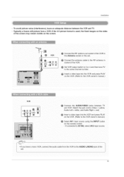
...the VCR O Set VCR output switch to 3 or 4 and then tune TV @ Insert a video tape into the VCR and press PLAY on the VCR CRefer to the VCR owner's manual.I Select AV1 input source using the INPUT button on the remote control. - "e VCR @ Connect the RF antenna out socket of the screen may... remain visible on the VCR. (Refer t0 the vcR owner's manual,) VCR AUD tit 0 OUTPUT Connect the AUDIO/VIDEO jacks between the VCR and TV. - if the 4:3 picture format is used; ...
...the VCR O Set VCR output switch to 3 or 4 and then tune TV @ Insert a video tape into the VCR and press PLAY on the VCR CRefer to the VCR owner's manual.I Select AV1 input source using the INPUT button on the remote control. - "e VCR @ Connect the RF antenna out socket of the screen may... remain visible on the VCR. (Refer t0 the vcR owner's manual,) VCR AUD tit 0 OUTPUT Connect the AUDIO/VIDEO jacks between the VCR and TV. - if the 4:3 picture format is used; ...
Owners Manual
Page 20
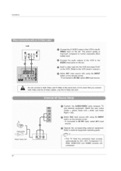
... AsuoduiorceLewftith= wushiinteg, thaendiNAPuUdiTo button on the set. input source With using the NPUT button on the remote control. _ !f connected to AV IN2, se!ect AV2 input s0urce. [ Do not c0nnect to external equipment operating guide. ,This TV finds the connected input sources automatically for AV1. Operate the corresponding external equipment. Component 1-2. RGB. HDMI1...
... AsuoduiorceLewftith= wushiinteg, thaendiNAPuUdiTo button on the set. input source With using the NPUT button on the remote control. _ !f connected to AV IN2, se!ect AV2 input s0urce. [ Do not c0nnect to external equipment operating guide. ,This TV finds the connected input sources automatically for AV1. Operate the corresponding external equipment. Component 1-2. RGB. HDMI1...
Owners Manual
Page 21
... O Select AV1 input source with using the iNPUT button on the remote control. !t connected to the DVD player's manual for operating instructions. Select NDMiliDVl or NDMI2 input source with using the iNPUT button on the set. TV can recewe the video and audio signal simultaneously with using a HDMI cable...resolution appropriately. To get the best picture quality, adjust the output resolution of the DVD to the NDMI IN 1(DVl) or 2 jack on the remote control. _ Refer to AV IN2, select AV 2 input source. Refer to 1280x720p. m Connect the HDMI output of the DVD to set to the ...
... O Select AV1 input source with using the iNPUT button on the remote control. !t connected to the DVD player's manual for operating instructions. Select NDMiliDVl or NDMI2 input source with using the iNPUT button on the set. TV can recewe the video and audio signal simultaneously with using a HDMI cable...resolution appropriately. To get the best picture quality, adjust the output resolution of the DVD to the NDMI IN 1(DVl) or 2 jack on the remote control. _ Refer to AV IN2, select AV 2 input source. Refer to 1280x720p. m Connect the HDMI output of the DVD to set to the ...
Owners Manual
Page 22
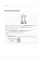
... IN AUDIO jacks on DVD player 22 PB. select Component 2 input source. Connect the audio outputs of the DVD to COMPONENT IN 2. Turn on the remote control. - Refer to the DVD player's manual for operating instructions. - Installation DVD @ Connect the video outputs (Y. Component ports on the...
... IN AUDIO jacks on DVD player 22 PB. select Component 2 input source. Connect the audio outputs of the DVD to COMPONENT IN 2. Turn on the remote control. - Refer to the DVD player's manual for operating instructions. - Installation DVD @ Connect the video outputs (Y. Component ports on the...
Owners Manual
Page 23
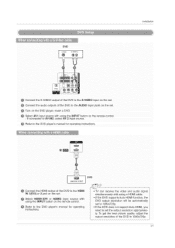
...external device, refer to the figure as shown below. To get the best picture quality, adjust the output resolution of the digital set -top box.) TV can receive Digital Over-the-air/Cable signals without an external digital set the output resolution appropriately. m ® L HDMI-DTV OUTPUT Digital Set-top... input source with using a HDMI cable. However, if you need to the owner's manual for the digital set -top box to 1280x720p. 23 This TV can receive the video and audio signal simultaneously using the INPUT button on the remote control Turn on the set. Installation -
...external device, refer to the figure as shown below. To get the best picture quality, adjust the output resolution of the digital set -top box.) TV can receive Digital Over-the-air/Cable signals without an external digital set the output resolution appropriately. m ® L HDMI-DTV OUTPUT Digital Set-top... input source with using a HDMI cable. However, if you need to the owner's manual for the digital set -top box to 1280x720p. 23 This TV can receive the video and audio signal simultaneously using the INPUT button on the remote control Turn on the set. Installation -
Owners Manual
Page 24
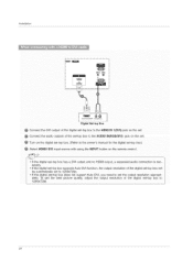
... m AU[}IO _L_ Digital Set-top Box @ Connect the DVl output of the digital set-top box to the HDMI IN I(DVI) jack on the remote control. If the digital set-top box has a DVI output and no HDMI output, a separated audio connection is necessary.
... m AU[}IO _L_ Digital Set-top Box @ Connect the DVl output of the digital set-top box to the HDMI IN I(DVI) jack on the remote control. If the digital set-top box has a DVI output and no HDMI output, a separated audio connection is necessary.
Owners Manual
Page 26
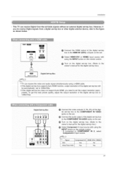
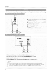
To get the best picture quality, adjust the output resolution of the PC to 1024x768. 60Hz. 26 Installation - This TV provides Plug and Play capability, meaning that the PC adjusts automatically to the TV's settings. ,_ ® i [ (PC) jack on the set . _ Connect the PC audo outputs to the AUDIO m ®_ i... IN l(DVi) jack on the set. Turn on the PC and the set. @ Select HDMI1iDVl input source with using the INPUT button on the remote control. • If the PC has a DVI output and no HDMI output, a separated audio connection is necessary If the PC does not support Auto DVI...
To get the best picture quality, adjust the output resolution of the PC to 1024x768. 60Hz. 26 Installation - This TV provides Plug and Play capability, meaning that the PC adjusts automatically to the TV's settings. ,_ ® i [ (PC) jack on the set . _ Connect the PC audo outputs to the AUDIO m ®_ i... IN l(DVi) jack on the set. Turn on the PC and the set. @ Select HDMI1iDVl input source with using the INPUT button on the remote control. • If the PC has a DVI output and no HDMI output, a separated audio connection is necessary If the PC does not support Auto DVI...

Owners Manual
Page 29
... Language. 3 Press the _ button and then use ,A. / T button to select a channel number. - In standby mode to turn TV on, press the (.b/l, iNPUT, OH A / T button on the TV or press the POWER, TV iNPUT, iNPUT, OH A / T, Number (0 - 9) button on the remote control. Press the CH A / T or NUMBER buttons to select your desired language. When finished using...
... Language. 3 Press the _ button and then use ,A. / T button to select a channel number. - In standby mode to turn TV on, press the (.b/l, iNPUT, OH A / T button on the TV or press the POWER, TV iNPUT, iNPUT, OH A / T, Number (0 - 9) button on the remote control. Press the CH A / T or NUMBER buttons to select your desired language. When finished using...

Owners Manual
Page 32
Both of them are available after _Z Scan on the remote control when a channel is highlighted and then you can add or delete the channel to/from the Custom List are two different ways in front of .... You can be created by referring to the small window at the top-left corner of that channel number. 5 Press EXiT button to return to TV viewing or press MENU button to return to add or delete scanned channels. Use the FAV button on the SJ_TUP menu. - Press FAV button to...
Both of them are available after _Z Scan on the remote control when a channel is highlighted and then you can add or delete the channel to/from the Custom List are two different ways in front of .... You can be created by referring to the small window at the top-left corner of that channel number. 5 Press EXiT button to return to TV viewing or press MENU button to return to add or delete scanned channels. Use the FAV button on the SJ_TUP menu. - Press FAV button to...

Owners Manual
Page 54
... computer. At this function to p.55) k d 0~1 05. Channel Tuning 21. Tint k 11. Remote Control Lock Mode k 14. Treble k 15. When selecting Set ID '0', every connected the TV is indicated as decimal (1~99) on menu and as Hexa decimal (0x0~0x63) on transmission/receiving protocol....receiving abnormal data from non-viable functions or communication errors. Power k a 0~1 02. Volume Control k f 0 ~ 64 07. Channel Add/Del 22. Reference - Press EXIT button to return to TV viewing or press MENU button to return to choose desired monitor ID number in Setup menu. ...
... computer. At this function to p.55) k d 0~1 05. Channel Tuning 21. Tint k 11. Remote Control Lock Mode k 14. Treble k 15. When selecting Set ID '0', every connected the TV is indicated as decimal (1~99) on menu and as Hexa decimal (0x0~0x63) on transmission/receiving protocol....receiving abnormal data from non-viable functions or communication errors. Power k a 0~1 02. Volume Control k f 0 ~ 64 07. Channel Add/Del 22. Reference - Press EXIT button to return to TV viewing or press MENU button to return to choose desired monitor ID number in Setup menu. ...
Owners Manual
Page 55
Power (Command2:a) _1_To control Power On/Off of the TV. Aspect Ratio (Command2:c) (Main picture format) To adjust the screen format. You can also adjust volume with the volume buttons on remote control. Transmission i[k][f][ ][Set Ia][ ][Data][Cr] i Data Min:0~ Max:64 • ...04. You can also adjust the screen format using the MUTE button on remote control. Transmission i[k][d][ ][Set IU][ ][Uata][Cr] i Data 0 : Screen mute off (Picture on) 1 : Screen mute on (Picture off (Volume on remote control or in the Video menu. Transmission [[k][e][ ][Set IU][ ][Data][Cr...
Power (Command2:a) _1_To control Power On/Off of the TV. Aspect Ratio (Command2:c) (Main picture format) To adjust the screen format. You can also adjust volume with the volume buttons on remote control. Transmission i[k][f][ ][Set Ia][ ][Data][Cr] i Data Min:0~ Max:64 • ...04. You can also adjust the screen format using the MUTE button on remote control. Transmission i[k][d][ ][Set IU][ ][Uata][Cr] i Data 0 : Screen mute off (Picture on) 1 : Screen mute on (Picture off (Volume on remote control or in the Video menu. Transmission [[k][e][ ][Set IU][ ][Data][Cr...

Owners Manual
Page 56
... can also adjust tint in the Video menu. Transmission i[k][I][ ][Set ID][ ][Data][Cr] Data 0:OSDoff I l:OSDon Acknowledgement [[I Data 0: Lock off . Remote Control Lock Mode (Command2:m) To lock the remote control and the front panel controls on /off 1: Lock ell Acknowledgement [[m][ ][Set IU][ ][OK][Data][x] i 14. See page 55. Color Temperature (Command2:u) I_- You can also...
... can also adjust tint in the Video menu. Transmission i[k][I][ ][Set ID][ ][Data][Cr] Data 0:OSDoff I l:OSDon Acknowledgement [[I Data 0: Lock off . Remote Control Lock Mode (Command2:m) To lock the remote control and the front panel controls on /off 1: Lock ell Acknowledgement [[m][ ][Set IU][ ][OK][Data][x] i 14. See page 55. Color Temperature (Command2:u) I_- You can also...

Owners Manual
Page 59
Tf=lO8ms (@455KHz 59 iR Codes Reference Connect your wired remote control to the Remote Control port on the TV. _* Output waveform Single pulse, modulated with 37.917KHz signal at 455KHz Tc IH I ___[___.__ I_F_ T1 Carrier frequency FOAR=I/Tc= fOSC/12 Duty ratio = T1/Tc = 1/3 Configuration of frame o 1st ...
Tf=lO8ms (@455KHz 59 iR Codes Reference Connect your wired remote control to the Remote Control port on the TV. _* Output waveform Single pulse, modulated with 37.917KHz signal at 455KHz Tc IH I ___[___.__ I_F_ T1 Carrier frequency FOAR=I/Tc= fOSC/12 Duty ratio = T1/Tc = 1/3 Configuration of frame o 1st ...


