
Owners Manual
Page 6
...77 77 Audio Menu 78 Options 78 79 79 80 80 Turning on the TV Volume Adjustment Channel Selection On Screen Menus Language Selection On Screen Menus Selection and Adjustment EZ Scan (Channel Search) Manual Scan Channel Edit DTV Signal Strength Channel Label Setup Main Picture Source Selection Input Label EZ Picture APM (Adaptive Picture Mode) Manual Picture Control (EZ Picture-Custom option) Color Temperature Control Video Reset Audio Language EZ SoundRite EZ Sound Manual Sound Control (EZ Sound-Custom option) Stereo/SAP Broadcasts Setup Front Surround TV Speakers On/Off Setup BBE 6
...77 77 Audio Menu 78 Options 78 79 79 80 80 Turning on the TV Volume Adjustment Channel Selection On Screen Menus Language Selection On Screen Menus Selection and Adjustment EZ Scan (Channel Search) Manual Scan Channel Edit DTV Signal Strength Channel Label Setup Main Picture Source Selection Input Label EZ Picture APM (Adaptive Picture Mode) Manual Picture Control (EZ Picture-Custom option) Color Temperature Control Video Reset Audio Language EZ SoundRite EZ Sound Manual Sound Control (EZ Sound-Custom option) Stereo/SAP Broadcasts Setup Front Surround TV Speakers On/Off Setup BBE 6

Owners Manual
Page 7
... Auto Clock Setup 81 Manual Clock Setup 82 On/Off Timer Setup 82 Sleep Timer 83 Auto Off 84 Aspect Ratio Control 85 Cinema 3:2 Mode Setup 85 Caption 86 Caption/Text 87 Caption Option 87 Auto Demo (Review) 88 Logo Light 88 Freeze & Magnify (DTV/CADTV 720p or 1080i mode only) 89~90 Parental Lock Setup 91 Cable Menu Options 91 Scrambled Channel 92 Cable Channel List 92 Emergency Alert Message 93 Brief Info. 94 Watching PIP/POP/Twin Picture 94 Selecting an Input Signal...
... Auto Clock Setup 81 Manual Clock Setup 82 On/Off Timer Setup 82 Sleep Timer 83 Auto Off 84 Aspect Ratio Control 85 Cinema 3:2 Mode Setup 85 Caption 86 Caption/Text 87 Caption Option 87 Auto Demo (Review) 88 Logo Light 88 Freeze & Magnify (DTV/CADTV 720p or 1080i mode only) 89~90 Parental Lock Setup 91 Cable Menu Options 91 Scrambled Channel 92 Cable Channel List 92 Emergency Alert Message 93 Brief Info. 94 Watching PIP/POP/Twin Picture 94 Selecting an Input Signal...
Owners Manual
Page 22
...press PLAY on the VCR. (Refer to the VCR owner's manual.) 3 Select Video1 input source using the TV/VIDEO button on the screen. If connected to IN2 (or VIDEO2), select Video2 input source. • If you have a mono VCR, connect the audio cable from a VCR. Installation VCR Setup - When connecting with a RCA cable 32, 37, 42 inch TV Back R AUDIO L (MONO) VIDEO S-VIDEO MONITOR OUT VIDEO1 COMPONENT1 R L AUDIO INPUT VIDEO INPUT 1 ANT IN ANT OUT S-VIDEO OUT OUTPUT SWITCH 34 (R) AUDIO (L) IN VIDEO VCR 26 inch TV Back DIGITAL AUDIO OUTPUT (OPTICAL) DVI INPUT HDMI IEEE...
...press PLAY on the VCR. (Refer to the VCR owner's manual.) 3 Select Video1 input source using the TV/VIDEO button on the screen. If connected to IN2 (or VIDEO2), select Video2 input source. • If you have a mono VCR, connect the audio cable from a VCR. Installation VCR Setup - When connecting with a RCA cable 32, 37, 42 inch TV Back R AUDIO L (MONO) VIDEO S-VIDEO MONITOR OUT VIDEO1 COMPONENT1 R L AUDIO INPUT VIDEO INPUT 1 ANT IN ANT OUT S-VIDEO OUT OUTPUT SWITCH 34 (R) AUDIO (L) IN VIDEO VCR 26 inch TV Back DIGITAL AUDIO OUTPUT (OPTICAL) DVI INPUT HDMI IEEE...

Owners Manual
Page 23
...IN VCR DIGITAL AUDIO OUTPUT (OPTICAL) DVI INPUT HDMI IEEE 1394 COMPONENT1 R AUDIO L (MONO) VIDEO S-VIDEO VIDEO1 VIDEO INPUT AUDIO INPUT L R COMPONENT1 INPUT 2 1 ANT IN OUT S-VIDEO (R) AUDIO (L) VIDEO OUTPUT SWITCH IN 34 ANT OUT VCR 1 Connect the S-VIDEO output of the VCR to the AUDIO input jacks on the remote control. - If connected to both Video and S-Video at the same time. 23 Do not connect to IN2 (or VIDEO2), select Video2 input source. compared to normal composite (RCA cable) input. 2 Connect the audio outputs of the VCR to the S-VIDEO input on the set...
...IN VCR DIGITAL AUDIO OUTPUT (OPTICAL) DVI INPUT HDMI IEEE 1394 COMPONENT1 R AUDIO L (MONO) VIDEO S-VIDEO VIDEO1 VIDEO INPUT AUDIO INPUT L R COMPONENT1 INPUT 2 1 ANT IN OUT S-VIDEO (R) AUDIO (L) VIDEO OUTPUT SWITCH IN 34 ANT OUT VCR 1 Connect the S-VIDEO output of the VCR to the AUDIO input jacks on the remote control. - If connected to both Video and S-Video at the same time. 23 Do not connect to IN2 (or VIDEO2), select Video2 input source. compared to normal composite (RCA cable) input. 2 Connect the audio outputs of the VCR to the S-VIDEO input on the set...

Owners Manual
Page 24
... 26 inch TV Back DIGITAL AUDIO OUTPUT (OPTICAL) DVI INPUT HDMI IEEE 1394 COMPONENT1 COMPONENT1 INPUT AUDIO INPUT L R 2 1 DVD S-VIDEO (R) AUDIO (L) 1 Connect the S-VIDEO output of the DVD to the S-VIDEO input on the set. (R) AUDIO (L) S-VIDEO DVD 2 Connect the audio outputs of the DVD to 1280x720p. To get the best picture quality, adjust the output resolution of the DVD to the AUDIO input jacks on the set. 3 Turn on the DVD player, insert a DVD. 4 Select Video1 input source with using the TV/VIDEO button on the remote control. 3 Refer to the DVD player's manual for...
... 26 inch TV Back DIGITAL AUDIO OUTPUT (OPTICAL) DVI INPUT HDMI IEEE 1394 COMPONENT1 COMPONENT1 INPUT AUDIO INPUT L R 2 1 DVD S-VIDEO (R) AUDIO (L) 1 Connect the S-VIDEO output of the DVD to the S-VIDEO input on the set. (R) AUDIO (L) S-VIDEO DVD 2 Connect the audio outputs of the DVD to 1280x720p. To get the best picture quality, adjust the output resolution of the DVD to the AUDIO input jacks on the set. 3 Turn on the DVD player, insert a DVD. 4 Select Video1 input source with using the TV/VIDEO button on the remote control. 3 Refer to the DVD player's manual for...

Owners Manual
Page 25
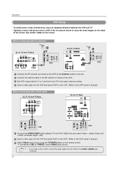
...Component 2 input source. • Digital Audio operation has priority if Digital Audio and AUDIO L/R are connected at the same time. 25 Installation When connecting with using the TV/VIDEO button on the remote control. - If connected to COMPONENT2 input, select Component 2 input source. 5 Refer to the DIGITAL AUDIO COMPONENT1 INPUT jack on the set. 3 Turn on the DVD player, insert a DVD. 4 Select Component 1 input source with a component cable 32, 37, 42 inch TV Back DIGITAL AUDIO (OPTICAL) OUTPUT RS-232C INPUT (CONTROL/SERVICE) DVI INPUT R AUDIO L (MONO) VIDEO S-VIDEO MONITOR...
...Component 2 input source. • Digital Audio operation has priority if Digital Audio and AUDIO L/R are connected at the same time. 25 Installation When connecting with using the TV/VIDEO button on the remote control. - If connected to COMPONENT2 input, select Component 2 input source. 5 Refer to the DIGITAL AUDIO COMPONENT1 INPUT jack on the set. 3 Turn on the DVD player, insert a DVD. 4 Select Component 1 input source with a component cable 32, 37, 42 inch TV Back DIGITAL AUDIO (OPTICAL) OUTPUT RS-232C INPUT (CONTROL/SERVICE) DVI INPUT R AUDIO L (MONO) VIDEO S-VIDEO MONITOR...

Owners Manual
Page 26
... INPUT) jack on the set. 2 Connect the audio outputs of the set-top box to the PC AUDIO INPUT jack on the set. 3 Turn on the remote control. 26 Installation HDSTB Setup - However, if you do receive Digital signals from a digital set-top box or other digital external device, refer to the owner's manual for the digital set-top box.) 4 Select RGB-DTV input source with using the TV/VIDEO button on the digital set -top box. This TV can receive Digital Over-the-air/Cable signals without an external digital set -top box...
... INPUT) jack on the set. 2 Connect the audio outputs of the set-top box to the PC AUDIO INPUT jack on the set. 3 Turn on the remote control. 26 Installation HDSTB Setup - However, if you do receive Digital signals from a digital set-top box or other digital external device, refer to the owner's manual for the digital set-top box.) 4 Select RGB-DTV input source with using the TV/VIDEO button on the digital set -top box. This TV can receive Digital Over-the-air/Cable signals without an external digital set -top box...
Owners Manual
Page 27
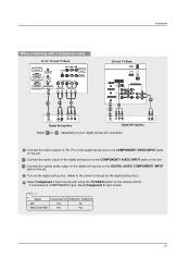
... VIDEO INPUT jacks on the set. 2-1 Connect the audio output of the digital set-top box to the COMPONENT1 AUDIO INPUT jacks on the set. 2-2 Connect the optical audio output of the digital set-top box to the DIGITAL AUDIO COMPONENT1 INPUT jack on the set. 3 Turn on the digital set -top box.) 4 Select Component 1 input source with using the TV/VIDEO button on the remote control. - Signal Component1/2 RGB-DTV, HDMI/DVI 480i Yes No 480p/720p/1080i Yes Yes 27 If connected to the owner's manual for the digital set -top box. (Refer to COMPONENT2 input, select Component 2 input...
... VIDEO INPUT jacks on the set. 2-1 Connect the audio output of the digital set-top box to the COMPONENT1 AUDIO INPUT jacks on the set. 2-2 Connect the optical audio output of the digital set-top box to the DIGITAL AUDIO COMPONENT1 INPUT jack on the set. 3 Turn on the digital set -top box.) 4 Select Component 1 input source with using the TV/VIDEO button on the remote control. - Signal Component1/2 RGB-DTV, HDMI/DVI 480i Yes No 480p/720p/1080i Yes Yes 27 If connected to the owner's manual for the digital set -top box. (Refer to COMPONENT2 input, select Component 2 input...
Owners Manual
Page 28
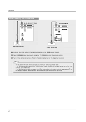
...digital set-top box does not support Auto HDMI, you need to the owner's manual for the digital set-top box.) • TV can receive the video and audio signal simultaneously with using a HDMI cable. • If the digital set-top box supports Auto HDMI function, output resolution of the digital set-top box to 1280x720p. 28 Installation When connecting with a HDMI cable 32, 37, 42 inch TV Back HDMI IEEE 1394 CableCARD 1 CABLE 26 inch TV Back HDMI IEEE 1394 CableCARD 1 COMPONENT1 AUDIO INPUT L VIDEO INPUT ANTENNA R HDMI-DTV OUPUT Digital Set-top Box HDMI-DTV OUPUT Digital...
...digital set-top box does not support Auto HDMI, you need to the owner's manual for the digital set-top box.) • TV can receive the video and audio signal simultaneously with using a HDMI cable. • If the digital set-top box supports Auto HDMI function, output resolution of the digital set-top box to 1280x720p. 28 Installation When connecting with a HDMI cable 32, 37, 42 inch TV Back HDMI IEEE 1394 CableCARD 1 CABLE 26 inch TV Back HDMI IEEE 1394 CableCARD 1 COMPONENT1 AUDIO INPUT L VIDEO INPUT ANTENNA R HDMI-DTV OUPUT Digital Set-top Box HDMI-DTV OUPUT Digital...
Owners Manual
Page 29
... picture quality, adjust the output resolution of the digital set-top box will be auto- matically set to 1280x720p. • If the digital set-top box does not support Auto DVI, you need to 1280x720p. 29 Installation When connecting with a HDMI to DVI cable 32, 37, 42 inch TV Back HDMI G-LINK DIGITAL AUDIO (OPTICAL) OUTPUT REMOTE RS-232C INPUT CONTROL (CONTROL/SERVICE) DVI INPUT R AUDIO L (MONO) VIDEO S-VIDEO MONITOR OUT VIDEO1 CABLE IEEE 1394 COMPONENT1 PC AUDIO INPUT RGB INPUT COMPONENT1 (PC/DTV INPUT) INPUT R L AUDIO INPUT VIDEO INPUT ANTENNA 1 2-1 2-2 26 inch...
... picture quality, adjust the output resolution of the digital set-top box will be auto- matically set to 1280x720p. • If the digital set-top box does not support Auto DVI, you need to 1280x720p. 29 Installation When connecting with a HDMI to DVI cable 32, 37, 42 inch TV Back HDMI G-LINK DIGITAL AUDIO (OPTICAL) OUTPUT REMOTE RS-232C INPUT CONTROL (CONTROL/SERVICE) DVI INPUT R AUDIO L (MONO) VIDEO S-VIDEO MONITOR OUT VIDEO1 CABLE IEEE 1394 COMPONENT1 PC AUDIO INPUT RGB INPUT COMPONENT1 (PC/DTV INPUT) INPUT R L AUDIO INPUT VIDEO INPUT ANTENNA 1 2-1 2-2 26 inch...

Owners Manual
Page 30
... operating guide. Installation Camcorder Video Game Set External AV Source Setup S-VIDEO VIDEO 2 R (MONO) L VIDEO AUDIO COMPONENT 2 1 VIDEO TV Side R AUDIO L VIDEO 1 Connect the AUDIO/VIDEO jacks between TV and external equipment. Digital Audio Output - If connected to p.80) CAUTION Do not look into the optical output port. Send the TV's audio to external audio equipment (stereo system) via the Digital Audio Output Optical port. 32, 37, 42 inch TV Back 26 inch TV Back AC IN G-LINK DIGITAL AUDIO (OPTICAL) OUTPUT REMOTE RS-232C INPUT CONTROL (CONTROL/SERVICE) DVI INPUT...
... operating guide. Installation Camcorder Video Game Set External AV Source Setup S-VIDEO VIDEO 2 R (MONO) L VIDEO AUDIO COMPONENT 2 1 VIDEO TV Side R AUDIO L VIDEO 1 Connect the AUDIO/VIDEO jacks between TV and external equipment. Digital Audio Output - If connected to p.80) CAUTION Do not look into the optical output port. Send the TV's audio to external audio equipment (stereo system) via the Digital Audio Output Optical port. 32, 37, 42 inch TV Back 26 inch TV Back AC IN G-LINK DIGITAL AUDIO (OPTICAL) OUTPUT REMOTE RS-232C INPUT CONTROL (CONTROL/SERVICE) DVI INPUT...

Owners Manual
Page 31
...'s input settings. • Component 1-2, RGB-PC/RGB-DTV, HDMI/DVI input sources can be used for Monitor out. • When connecting with external audio equipments, such as this may cause damage to p.80) CableCARDTM Setup 32, 37, 42 inch TV Back 26 inch TV Back HDMI IEEE 1394 CableCARD CABLE HDMI IEEE 1394 CableCARD COMPONENT1 AUDIO INPUT L VIDEO INPUT R ANTENNA - To view the premium stations Insert the CableCARDTM received from Cable Service provider to hook up...
...'s input settings. • Component 1-2, RGB-PC/RGB-DTV, HDMI/DVI input sources can be used for Monitor out. • When connecting with external audio equipments, such as this may cause damage to p.80) CableCARDTM Setup 32, 37, 42 inch TV Back 26 inch TV Back HDMI IEEE 1394 CableCARD CABLE HDMI IEEE 1394 CableCARD COMPONENT1 AUDIO INPUT L VIDEO INPUT R ANTENNA - To view the premium stations Insert the CableCARDTM received from Cable Service provider to hook up...
Owners Manual
Page 43
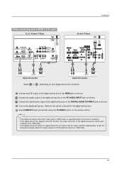
... a Cable Box 32, 37, 42 inch TV Back 26 inch TV Back Installation AC IN HDMI G-LINK DIGITAL AUDIO (OPTICAL) OUTPUT REMOTE RS-232C INPUT CONTROL (CONTROL/SERVICE) DVI INPUT R AUDIO L (MONO) VIDEO S-VIDEO MONITOR OUT VIDEO1 CABLE IEEE 1394 COMPONENT1 PC AUDIO INPUT RGB INPUT COMPONENT1 (PC/DTV INPUT) INPUT R L AUDIO INPUT VIDEO INPUT ANTENNA CableCARD VCR Front VCR Back AC IN G-LINK DIGITAL AUDIO OUTPUT (OPTICAL) REMOTE RS-232C INPUT DVI INPUT CONTROL (CONTROL/SERVICE PORT) PC AUDIO RGB INPUT COMPONENT1 INPUT INPUT (PC/DTV INPUT) R AUDIO L (MONO) VIDEO...
... a Cable Box 32, 37, 42 inch TV Back 26 inch TV Back Installation AC IN HDMI G-LINK DIGITAL AUDIO (OPTICAL) OUTPUT REMOTE RS-232C INPUT CONTROL (CONTROL/SERVICE) DVI INPUT R AUDIO L (MONO) VIDEO S-VIDEO MONITOR OUT VIDEO1 CABLE IEEE 1394 COMPONENT1 PC AUDIO INPUT RGB INPUT COMPONENT1 (PC/DTV INPUT) INPUT R L AUDIO INPUT VIDEO INPUT ANTENNA CableCARD VCR Front VCR Back AC IN G-LINK DIGITAL AUDIO OUTPUT (OPTICAL) REMOTE RS-232C INPUT DVI INPUT CONTROL (CONTROL/SERVICE PORT) PC AUDIO RGB INPUT COMPONENT1 INPUT INPUT (PC/DTV INPUT) R AUDIO L (MONO) VIDEO...

Owners Manual
Page 70
... TV Speaker LOCK BBE CABLE SETUP VIDEO AUDIO TIME OPTION Lock System Set Password Block Channel Movie Rating TV Rating-Children TV Rating-General Input Block LOCk G CABLE SETUP VIDEO AUDIO TIME OPTION G LOCK Aspect Ratio Cinema 3:2 Mode Caption Caption/Text Caption Option Language Auto Demo Logo Light CABLE SETUP VIDEO AUDIO TIME G OPTION LOCK CABLE Auto Clock Manual Clock Off Timer On Timer Sleep Timer Auto Off • Your TV's OSD (On Screen Display) may differ slightly from what is shown in this manual. 70 Press the G button and then use D / E / F / G button to adjust the...
... TV Speaker LOCK BBE CABLE SETUP VIDEO AUDIO TIME OPTION Lock System Set Password Block Channel Movie Rating TV Rating-Children TV Rating-General Input Block LOCk G CABLE SETUP VIDEO AUDIO TIME OPTION G LOCK Aspect Ratio Cinema 3:2 Mode Caption Caption/Text Caption Option Language Auto Demo Logo Light CABLE SETUP VIDEO AUDIO TIME G OPTION LOCK CABLE Auto Clock Manual Clock Off Timer On Timer Sleep Timer Auto Off • Your TV's OSD (On Screen Display) may differ slightly from what is shown in this manual. 70 Press the G button and then use D / E / F / G button to adjust the...

Owners Manual
Page 71
...-air) TV signal CATV Analog cable TV signal CADTV Digital cable TV signal 71 Manual Scan SETUP G VIDEO AUDIO TIME OPTION LOCK EZ Scan Manual Scan Channel Edit DTV Signal Channel Label Main Input Sub Input Input Label Set ID CABLE SETUP VIDEO AUDIO TIME OPTION LOCK CABLE EZ Scan Manual Scan Channel Edit DTV Signal Channel Label Main Input Sub Input Input Label Set ID MENU Previous G Select channel type and RF-channel number. A password is turned on . - Operation Setup Menu Options EZ Scan (Channel Search) SETUP G VIDEO AUDIO TIME OPTION LOCK EZ Scan Manual Scan Channel Edit DTV...
...-air) TV signal CATV Analog cable TV signal CADTV Digital cable TV signal 71 Manual Scan SETUP G VIDEO AUDIO TIME OPTION LOCK EZ Scan Manual Scan Channel Edit DTV Signal Channel Label Main Input Sub Input Input Label Set ID CABLE SETUP VIDEO AUDIO TIME OPTION LOCK CABLE EZ Scan Manual Scan Channel Edit DTV Signal Channel Label Main Input Sub Input Input Label Set ID MENU Previous G Select channel type and RF-channel number. A password is turned on . - Operation Setup Menu Options EZ Scan (Channel Search) SETUP G VIDEO AUDIO TIME OPTION LOCK EZ Scan Manual Scan Channel Edit DTV...

Owners Manual
Page 72
... Guide On Screen system Setup, cable channels (CATV or CADTV) will appear in front of channel lists in memory: "Custom list" and "Favorite channel list" from the default channel list created from the Custom List are displayed in black color, and the channels deleted from the EZ Scan channel search. - Operation Setup Menu Options continued SETUP G VIDEO AUDIO TIME OPTION LOCK EZ Scan Manual Scan Channel Edit DTV Signal Channel Label Main Input Sub Input Input Label Set ID CABLE Channel Edit SETUP VIDEO AUDIO TIME OPTION LOCK CABLE EZ Scan Manual Scan Channel Edit DTV Signal Channel...
... Guide On Screen system Setup, cable channels (CATV or CADTV) will appear in front of channel lists in memory: "Custom list" and "Favorite channel list" from the default channel list created from the Custom List are displayed in black color, and the channels deleted from the EZ Scan channel search. - Operation Setup Menu Options continued SETUP G VIDEO AUDIO TIME OPTION LOCK EZ Scan Manual Scan Channel Edit DTV Signal Channel Label Main Input Sub Input Input Label Set ID CABLE Channel Edit SETUP VIDEO AUDIO TIME OPTION LOCK CABLE EZ Scan Manual Scan Channel Edit DTV Signal Channel...
Owners Manual
Page 89
...- For USA Ratings for all programming) Input Block • Video 1, 2 • Component 1, 2 • RGB and HDMI/DVI (On, Off) (On, Off) (On, Off) 89 sexual situations (applies to TV-PG, TV-14, TV-MA) • Violence (applies to -video movies use this function, the following must be blocked. Operation Lock Menu Options Parental Control can be avail- The Parental Control Function (V-Chip) is to allow...
...- For USA Ratings for all programming) Input Block • Video 1, 2 • Component 1, 2 • RGB and HDMI/DVI (On, Off) (On, Off) (On, Off) 89 sexual situations (applies to TV-PG, TV-14, TV-MA) • Violence (applies to -video movies use this function, the following must be blocked. Operation Lock Menu Options Parental Control can be avail- The Parental Control Function (V-Chip) is to allow...
Owners Manual
Page 91
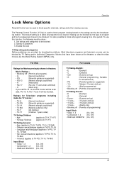
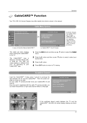
... the CableCARDTM. Operation Cable Menu Options SETUP SA CableCARD™ Diag Screen G VIDEO SA CableCARD™/Host ID Screen AUDIO TIME OPTION LOCK CABLE MENU Previous In case of Scientific Atlanta CableCARD™ CableCARD(tm) Message In order to the right. - Scrambled Channel - Once the card is Motorola, Scientific Atlanta (SA), or SCM etc. The CableCARDTM type is registered with the cable TV service provider, you...
... the CableCARDTM. Operation Cable Menu Options SETUP SA CableCARD™ Diag Screen G VIDEO SA CableCARD™/Host ID Screen AUDIO TIME OPTION LOCK CABLE MENU Previous In case of Scientific Atlanta CableCARD™ CableCARD(tm) Message In order to the right. - Scrambled Channel - Once the card is Motorola, Scientific Atlanta (SA), or SCM etc. The CableCARDTM type is registered with the cable TV service provider, you...
Owners Manual
Page 110
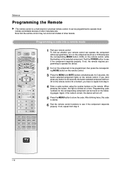
... if the component responds properly. Programming code numbers for 20 seconds, the button selected component will turn off on the remote. Programming a code into a remote mode TV INPUT POWER TV AUDIO DVD MODE CABLE TV/VIDEO VCR STB DAY MENU DAY+ TV GUIDE ENTER EXIT 1394 MARK INFO i PAGE VOL MUTE FAV CH PAGE 1 2 3 4 5 6 7 8 9 0 FLASHBK PIP PIP CH- If not, repeat from step 2. 4 Enter a code number using the number buttons on the remote control. Reference Programming the Remote G The remote control is blinked at a time. At...
... if the component responds properly. Programming code numbers for 20 seconds, the button selected component will turn off on the remote. Programming a code into a remote mode TV INPUT POWER TV AUDIO DVD MODE CABLE TV/VIDEO VCR STB DAY MENU DAY+ TV GUIDE ENTER EXIT 1394 MARK INFO i PAGE VOL MUTE FAV CH PAGE 1 2 3 4 5 6 7 8 9 0 FLASHBK PIP PIP CH- If not, repeat from step 2. 4 Enter a code number using the number buttons on the remote control. Reference Programming the Remote G The remote control is blinked at a time. At...
Owners Manual
Page 113
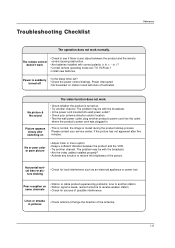
...'s power cord into wall power outlet? • Check your service center, if the picture has not appeared after switching on some channels • Station or cable product experiencing problems, tune to another channel. No or poor color or poor picture • Adjust Color in menu option. • Keep a sufficient distance between the product and the remote control causing obstruction. • Are batteries installed with Auto off • Is the sleep timer set : TV, VCR...
...'s power cord into wall power outlet? • Check your service center, if the picture has not appeared after switching on some channels • Station or cable product experiencing problems, tune to another channel. No or poor color or poor picture • Adjust Color in menu option. • Keep a sufficient distance between the product and the remote control causing obstruction. • Are batteries installed with Auto off • Is the sleep timer set : TV, VCR...


