Owner's Manual
Page 9
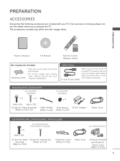
... 19/22/26LE5300, 22/26LE5500 (For 26LE5300, 26LE5500) (For 26LE5300, 26LE5500) x 4 x 4 1.5V 1.5V x 4 1,5Vcc 1,5Vcc (M4 x 14) (M4 x 20) Screws for stand assembly (Refer to P.20, 22) Cable Holder (Refer to p.31) Ring spacers AC/DC Adapter (Refer to p.29) Power Cord 32/37/42/47LD450, 37/42...47LD450C, 42/47/55LD630 (For 32/37/42LD450, 37/42/LD450C, 42LD630) x 8 1.5V 1.5V 1,5Vcc 1,5Vcc (M4 x 20) Screws for stand Screws for stand fixing assembly (Refer to P.33) (Refer to P.24) Protection Cover (Refer to P.25) Power Cord (For 37/42/47LD450C) Protective Bracket and Screw for Power ...
... 19/22/26LE5300, 22/26LE5500 (For 26LE5300, 26LE5500) (For 26LE5300, 26LE5500) x 4 x 4 1.5V 1.5V x 4 1,5Vcc 1,5Vcc (M4 x 14) (M4 x 20) Screws for stand assembly (Refer to P.20, 22) Cable Holder (Refer to p.31) Ring spacers AC/DC Adapter (Refer to p.29) Power Cord 32/37/42/47LD450, 37/42...47LD450C, 42/47/55LD630 (For 32/37/42LD450, 37/42/LD450C, 42LD630) x 8 1.5V 1.5V 1,5Vcc 1,5Vcc (M4 x 20) Screws for stand Screws for stand fixing assembly (Refer to P.33) (Refer to P.24) Protection Cover (Refer to P.25) Power Cord (For 37/42/47LD450C) Protective Bracket and Screw for Power ...
Owner's Manual
Page 10
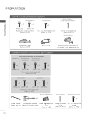
... (For 55LD520C) x 4 x 4 (M4 x 24) (M4 x 14) Screws for stand assembly (Refer to P.26) x 2 Torx plus Star head screw (Refer to P.26) (Except 47LD420, 47/55LD520, 55LD520C) Screw for stand fixing (Refer to P.33) (For 55LD520C) 1.5V 1.5V 1,5Vcc 1,5Vcc Protection Cover (...x 4 x 4 x 4 (M4 x 22) (M4 x 24) (M4 x 26) (M4 x 16) Screws for stand assembly (Refer to P.22) (42/47LE7300) (55LE7300) x 3 x 4 x 3 x 4 (M4 x 20) (M4 x 12) (M4 x 26) (M4 x 16) Screws for stand assembly (Refer to P.21) (For 42/47/55LE7300) x 2 (For 32LE5300) (For 42/47/55LE530C) x 2 Cable Holder Component...
... (For 55LD520C) x 4 x 4 (M4 x 24) (M4 x 14) Screws for stand assembly (Refer to P.26) x 2 Torx plus Star head screw (Refer to P.26) (Except 47LD420, 47/55LD520, 55LD520C) Screw for stand fixing (Refer to P.33) (For 55LD520C) 1.5V 1.5V 1,5Vcc 1,5Vcc Protection Cover (...x 4 x 4 x 4 (M4 x 22) (M4 x 24) (M4 x 26) (M4 x 16) Screws for stand assembly (Refer to P.22) (42/47LE7300) (55LE7300) x 3 x 4 x 3 x 4 (M4 x 20) (M4 x 12) (M4 x 26) (M4 x 16) Screws for stand assembly (Refer to P.21) (For 42/47/55LE7300) x 2 (For 32LE5300) (For 42/47/55LE530C) x 2 Cable Holder Component...

Owner's Manual
Page 20
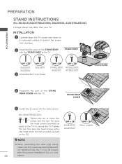
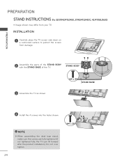
...shown may differ from TV. 4 Install the 4 screws into the holes shown. PREPARATION 2 Assemble the parts of the STAND BODY with the STAND BASE of the TV. STAND BASE 3 Assemble the TV as shown. 3 Detach the stand from your TV. INSTALLATION DETACHMENT 1 Carefully place the TV screen side down on a cushioned ... tightened fully, the TV can tilt forward after the product installation). Do not over tighten. 20 M4 x 14 ! ! STAND BODY 2 Remove the screws from damage. NOTE ►When assembling the desk type stand, make sure the screws are fully tightened (If ? ?
...shown may differ from TV. 4 Install the 4 screws into the holes shown. PREPARATION 2 Assemble the parts of the STAND BODY with the STAND BASE of the TV. STAND BASE 3 Assemble the TV as shown. 3 Detach the stand from your TV. INSTALLATION DETACHMENT 1 Carefully place the TV screen side down on a cushioned ... tightened fully, the TV can tilt forward after the product installation). Do not over tighten. 20 M4 x 14 ! ! STAND BODY 2 Remove the screws from damage. NOTE ►When assembling the desk type stand, make sure the screws are fully tightened (If ? ?

Owner's Manual
Page 21
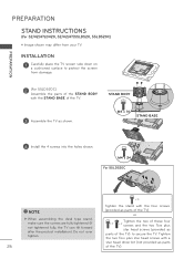
...the TV can tilt forward after the product installation). STAND INSTRUCTIONS (For 42/47/55LE7300) ꔛ Image shown may differ from TV. 4 Install the 4 screws into the holes shown. M4 x 20 42/47LE7300 M4 x 26 55LE7300 STAND BODY STAND BASE 3 Assemble the TV as shown. 2 Remove the screws ...from the TV. 3 Detach the stand from your TV. Do not over tighten. 21 PREPARATION 2 Assemble the parts of the STAND BODY with the STAND BASE of the TV. NOTE ►When assembling the desk type stand, make ...
...the TV can tilt forward after the product installation). STAND INSTRUCTIONS (For 42/47/55LE7300) ꔛ Image shown may differ from TV. 4 Install the 4 screws into the holes shown. M4 x 20 42/47LE7300 M4 x 26 55LE7300 STAND BODY STAND BASE 3 Assemble the TV as shown. 2 Remove the screws ...from the TV. 3 Detach the stand from your TV. Do not over tighten. 21 PREPARATION 2 Assemble the parts of the STAND BODY with the STAND BASE of the TV. NOTE ►When assembling the desk type stand, make ...
Owner's Manual
Page 22
...For 26/32/37/42/47/55LE5300, 26LE5500, 42/47/55LE530C) ꔛ Image shown may differ from damage. 2 Assemble the parts of the STAND BODY with the STAND BASE of the STAND REAR COVER with a star head driver bit (not provided as shown. Tighten the two Torx plus star head screws (...not tightened fully, the TV can tilt forward after the product installation). M4 x 24 M4 x 26 37/42LE5300, 47/55LE5300, 42LE530C 47/55LE530C STAND BASE 4 Assemble the part of the TV. INSTALLATION 1 Carefully place the TV screen side down on a cushioned surface to secure the TV. NOTE ►When...
...For 26/32/37/42/47/55LE5300, 26LE5500, 42/47/55LE530C) ꔛ Image shown may differ from damage. 2 Assemble the parts of the STAND BODY with the STAND BASE of the STAND REAR COVER with a star head driver bit (not provided as shown. Tighten the two Torx plus star head screws (...not tightened fully, the TV can tilt forward after the product installation). M4 x 24 M4 x 26 37/42LE5300, 47/55LE5300, 42LE530C 47/55LE530C STAND BASE 4 Assemble the part of the TV. INSTALLATION 1 Carefully place the TV screen side down on a cushioned surface to secure the TV. NOTE ►When...
Owner's Manual
Page 24
..., 37/42/47LD450C, 42/47/55LD630) ꔛ Image shown may differ from damage. AC IN CABLE MANAGEMENT AC IN 2 Assemble the parts of the STAND BODY with the STAND BASE of the TV. M4 x 20 STAND BASE AC IN CABLE MANAGEMENT AC IN 4 Install CABLEMANAGEMENT the 4 screws into the holes shown. ! ! Do not over...
..., 37/42/47LD450C, 42/47/55LD630) ꔛ Image shown may differ from damage. AC IN CABLE MANAGEMENT AC IN 2 Assemble the parts of the STAND BODY with the STAND BASE of the TV. M4 x 20 STAND BASE AC IN CABLE MANAGEMENT AC IN 4 Install CABLEMANAGEMENT the 4 screws into the holes shown. ! ! Do not over...
Owner's Manual
Page 26
... 32/42/47LD420, 32/42/47/55LD520, 55LD520C) ꔛ Image shown may differ from damage. 2 (For 55LD520C) Assemble the parts of the STAND BODY STAND BODY M4X20 with the STAND BASE of the TV. 3 Assemble the TV as parts of the TV). Tighten the two Torx plus star head screws (provided as parts of... the TV) to protect the screen from your TV. Do not over tighten. 26 x 4 Tighten the stand with a star...
... 32/42/47LD420, 32/42/47/55LD520, 55LD520C) ꔛ Image shown may differ from damage. 2 (For 55LD520C) Assemble the parts of the STAND BODY STAND BODY M4X20 with the STAND BASE of the TV. 3 Assemble the TV as parts of the TV). Tighten the two Torx plus star head screws (provided as parts of... the TV) to protect the screen from your TV. Do not over tighten. 26 x 4 Tighten the stand with a star...


