
Owner's Manual
Page 1
OWNER'S MANUAL LCD TV Please read this manual carefully before operating your set and retain it for future reference. 19LD350 22LD350 26LD350 32LD350 19LD350C 22LD350C 32LD320 P/NO : SAC34134202 (1008-REV04) www.lg.com
OWNER'S MANUAL LCD TV Please read this manual carefully before operating your set and retain it for future reference. 19LD350 22LD350 26LD350 32LD350 19LD350C 22LD350C 32LD320 P/NO : SAC34134202 (1008-REV04) www.lg.com

Owner's Manual
Page 9
...Remote Control, Batteries (AAA) Power Cord Not included with all models Polishing Cloth * Wipe spots on the exterior only with your TV. The accessories included may cause scratches or discoloration. PREPARATION PREPARATION ACCESSORIES Ensure that the following accessories are included with the polishing cloth... use shielded signal interface cables with ferrite cores to P.15) 9 For 19/22LD350, 19/22LD350C Cable Holder (Refer to P.19) For 26/32LD350 Protection Cover (Refer to P.14) x 8 (M4x20) Screws for stand assembly(Refer to P.16) For 32LD320 Screw for stand fixing (Refer ...
...Remote Control, Batteries (AAA) Power Cord Not included with all models Polishing Cloth * Wipe spots on the exterior only with your TV. The accessories included may cause scratches or discoloration. PREPARATION PREPARATION ACCESSORIES Ensure that the following accessories are included with the polishing cloth... use shielded signal interface cables with ferrite cores to P.15) 9 For 19/22LD350, 19/22LD350C Cable Holder (Refer to P.19) For 26/32LD350 Protection Cover (Refer to P.14) x 8 (M4x20) Screws for stand assembly(Refer to P.16) For 32LD320 Screw for stand fixing (Refer ...

Owner's Manual
Page 10
PREPARATION PREPARATION FRONT PANEL INFORMATION I Image shown may differ from your TV. 19/22LD350, 19/22LD350C MENU Button INPUT Button POWER Button ENTER Button VOLUME (-, +) Buttons CHANNEL ( , ) Buttons INPUT MENU ENTER VOL CH SPEAKER Remote Control Sensor Power/Standby Indicator Illuminates red in standby mode. Illuminates blue when the TV is switched on. 26/32LD350 CH VOL ENTER MENU INPUT CHANNEL ( , ) Buttons VOLUME (+, -) Buttons ENTER Button MENU Button INPUT Button POWER Button 10
PREPARATION PREPARATION FRONT PANEL INFORMATION I Image shown may differ from your TV. 19/22LD350, 19/22LD350C MENU Button INPUT Button POWER Button ENTER Button VOLUME (-, +) Buttons CHANNEL ( , ) Buttons INPUT MENU ENTER VOL CH SPEAKER Remote Control Sensor Power/Standby Indicator Illuminates red in standby mode. Illuminates blue when the TV is switched on. 26/32LD350 CH VOL ENTER MENU INPUT CHANNEL ( , ) Buttons VOLUME (+, -) Buttons ENTER Button MENU Button INPUT Button POWER Button 10

Owner's Manual
Page 13
... DC power. 13 Caution: Never attempt to this jack. 7 COMPONENT IN Analog Connection. I Image shown may differ from your TV. AC IN 11 PREPARATION AV IN 1 /DVI IN 32LD350, 32LD320 1 23 4 5 10 IN 2 USB IN 1 RS-232C IN (CONTROL&SERVICE) 1 OPTICAL H/P AUDIO IN DIGITAL (RGB/DVI) AUDIO OUT VIDEO L/MONO AUDIO R 9 VIDEO...
... DC power. 13 Caution: Never attempt to this jack. 7 COMPONENT IN Analog Connection. I Image shown may differ from your TV. AC IN 11 PREPARATION AV IN 1 /DVI IN 32LD350, 32LD320 1 23 4 5 10 IN 2 USB IN 1 RS-232C IN (CONTROL&SERVICE) 1 OPTICAL H/P AUDIO IN DIGITAL (RGB/DVI) AUDIO OUT VIDEO L/MONO AUDIO R 9 VIDEO...

Owner's Manual
Page 16
...INSTRUCTIONS (For 26/32LD350) I Image shown may differ from damage. 2 Assemble the parts of the STAND BODY with COVER BASE of the TV by using the holes in the back of the TV. ! INSTALLATION 1 Carefully place the TV screen side down on a cushioned surface to protect the screen from your TV. STAND BODY 3... Assemble the TV as shown. (M4x20) COVER BASE 4 Fix the 4 ...
...INSTRUCTIONS (For 26/32LD350) I Image shown may differ from damage. 2 Assemble the parts of the STAND BODY with COVER BASE of the TV by using the holes in the back of the TV. ! INSTALLATION 1 Carefully place the TV screen side down on a cushioned surface to protect the screen from your TV. STAND BODY 3... Assemble the TV as shown. (M4x20) COVER BASE 4 Fix the 4 ...
Owner's Manual
Page 18
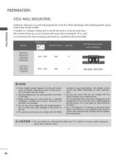
..., 22LD350, 100 * 100 M4 4 22LD350C 26LD350, 32LD350, 200 * 100 M4 4 32LD320 LSW100B, LSW100BG ! G Do not use fasten the screws too strongly, this may damage the TV or cause the TV to a fall and result in severe personal injury. G LG is not liable for wall mount kits are provided. ... used or the consumer fails to other building materials, please contact your nearest installer. G Do not use an LG brand wall mount when mounting the TV to the TV. G When purchasing our wall mount kit, a detailed installation manual and all parts necessary for these kinds of...
..., 22LD350, 100 * 100 M4 4 22LD350C 26LD350, 32LD350, 200 * 100 M4 4 32LD320 LSW100B, LSW100BG ! G Do not use fasten the screws too strongly, this may damage the TV or cause the TV to a fall and result in severe personal injury. G LG is not liable for wall mount kits are provided. ... used or the consumer fails to other building materials, please contact your nearest installer. G Do not use an LG brand wall mount when mounting the TV to the TV. G When purchasing our wall mount kit, a detailed installation manual and all parts necessary for these kinds of...

Owner's Manual
Page 19
For 19/22LD350, 19/22LD350C 1 After connecting the cables as necessary, install CABLE HOLDER as shown. To connect additional equipment, see the EXTERNAL EQUIPMENT SETUP section. 2 Open the CABLE MANAGEMENT CLIP as shown and bundle the cables. AC IN AC IN 19 AC IN AC IN AC-IN K AC IN AC IN AC IN CABLE MANAGEMENT CLIP AC IN 3 Put the cables inside the CABLE MANAGEMENT CLIP and snap it closed. PREPARATION CABLE MANAGEMENT I Image shown may differ from your TV. For 26/32LD350, 32LD320 1 Connect the cables as necessary.
For 19/22LD350, 19/22LD350C 1 After connecting the cables as necessary, install CABLE HOLDER as shown. To connect additional equipment, see the EXTERNAL EQUIPMENT SETUP section. 2 Open the CABLE MANAGEMENT CLIP as shown and bundle the cables. AC IN AC IN 19 AC IN AC IN AC-IN K AC IN AC IN AC IN CABLE MANAGEMENT CLIP AC IN 3 Put the cables inside the CABLE MANAGEMENT CLIP and snap it closed. PREPARATION CABLE MANAGEMENT I Image shown may differ from your TV. For 26/32LD350, 32LD320 1 Connect the cables as necessary.
Owner's Manual
Page 24
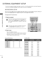
...00 59.94 60.00 How to connect 1 Connect the video outputs (Y, PB, PR) of the digital settop box to the owner's manual for 32LD350. Component Connection 1. I This part of the digital set -top box operation.) I To prevent the equipment damage, never plug in any power cords until.... However, if you have finished connecting all equipment. Match the jack colors (Y = green, PB = blue, and PR = red). HD RECEIVER SETUP This TV can receive digital over-the-air/digital cable signals without an external digital set -top box or other digital external device. Y PB PR L R 2 Connect ...
...00 59.94 60.00 How to connect 1 Connect the video outputs (Y, PB, PR) of the digital settop box to the owner's manual for 32LD350. Component Connection 1. I This part of the digital set -top box operation.) I To prevent the equipment damage, never plug in any power cords until.... However, if you have finished connecting all equipment. Match the jack colors (Y = green, PB = blue, and PR = red). HD RECEIVER SETUP This TV can receive digital over-the-air/digital cable signals without an external digital set -top box or other digital external device. Y PB PR L R 2 Connect ...
Owner's Manual
Page 25
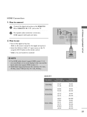
...to connect 1 Connect the digital set -top box.) I N or HDMI/DVI IN 1/2* jack on the TV. 2 No separate audio connection is necessary. In this case use I Turn on the remote control. * HDMI 2: For 26/32LD350, 32LD320 ! NOTE G If an HDMI cables doesn't support HDMI version 1.3, it can cause flickers or no... screen display. How to the HDMI/DVI I Select the HDMI or HDMI1/2* input source on the TV using the INPUT button on the digital set-top...
...to connect 1 Connect the digital set -top box.) I N or HDMI/DVI IN 1/2* jack on the TV. 2 No separate audio connection is necessary. In this case use I Turn on the remote control. * HDMI 2: For 26/32LD350, 32LD320 ! NOTE G If an HDMI cables doesn't support HDMI version 1.3, it can cause flickers or no... screen display. How to the HDMI/DVI I Select the HDMI or HDMI1/2* input source on the TV using the INPUT button on the digital set-top...
Owner's Manual
Page 28
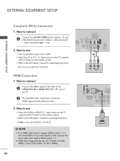
How to the DVD player's manual for operating instructions. * AV2: For 26/32LD350, 32LD320 HDMI Connection 1. Match the jack colors (Video = yellow, Audio Left = white, and Audio Right = red). 2. NOTE G If an HDMI cables doesn't support HDMI version 1.3, ... Composite (RCA) Connection 1. How to connect 1 Connect the HDMI output of the DVD to use I Select the HDMI or HDMI1 / 2* input source on the TV using the INPUT button on the TV. 2 No separated audio connection is necessary. HDMI supports both audio and video. 2. I Select the A V or AV1/2* input source on the...
How to the DVD player's manual for operating instructions. * AV2: For 26/32LD350, 32LD320 HDMI Connection 1. Match the jack colors (Video = yellow, Audio Left = white, and Audio Right = red). 2. NOTE G If an HDMI cables doesn't support HDMI version 1.3, ... Composite (RCA) Connection 1. How to connect 1 Connect the HDMI output of the DVD to use I Select the HDMI or HDMI1 / 2* input source on the TV using the INPUT button on the TV. 2 No separated audio connection is necessary. HDMI supports both audio and video. 2. I Select the A V or AV1/2* input source on the...
Owner's Manual
Page 29
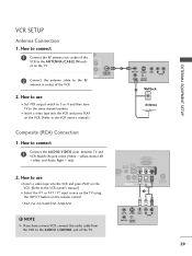
..., connect the audio cable from the VCR to the AUDIO L/MONO jack of the VCR. 2. I Set VCR output switch to 3 or 4 and then tune TV to the VCR owner's manual.) 1 ANT OUT S-VIDEO VIDEO L R AUDIO ANT IN OUTPUT SWITCH 2 Wall Jack Antenna Composite (RCA) Connection 1. How to ...the VCR owner's manual.) I Insert a video tape into the VCR and press PLAY on the remote control. * AV2: For 26/32LD350, 32LD320 ! RS-232C IN (CONTROL&SERVICE) OPTICAL AUDIO IN DIGITAL (RGB/DVI) AUDIO OUT VIDEO L/MONO AUDIO R IN (PC) Y PB PR L R VIDEO ...
..., connect the audio cable from the VCR to the AUDIO L/MONO jack of the VCR. 2. I Set VCR output switch to 3 or 4 and then tune TV to the VCR owner's manual.) 1 ANT OUT S-VIDEO VIDEO L R AUDIO ANT IN OUTPUT SWITCH 2 Wall Jack Antenna Composite (RCA) Connection 1. How to ...the VCR owner's manual.) I Insert a video tape into the VCR and press PLAY on the remote control. * AV2: For 26/32LD350, 32LD320 ! RS-232C IN (CONTROL&SERVICE) OPTICAL AUDIO IN DIGITAL (RGB/DVI) AUDIO OUT VIDEO L/MONO AUDIO R IN (PC) Y PB PR L R VIDEO ...

Owner's Manual
Page 30
... or AV IN 1 input, select the A V or A V 1 input source on the side of TV. 2. How to connect 1 Connect the AUDIO/VIDEO jacks between TV and external equipment. EXTERNAL EQUIPMENT SETUP EXTERNAL EQUIPMENT SETUP OTHER A/V SOURCE SETUP 1. Match the jack colors. (Video... = yellow, Audio Left = white, and Audio Right = red) 2. How to use I After connecting the USB I N jack, you use I Operate the corresponding external equipment. * AV2: For 26/32LD350...
... or AV IN 1 input, select the A V or A V 1 input source on the side of TV. 2. How to connect 1 Connect the AUDIO/VIDEO jacks between TV and external equipment. EXTERNAL EQUIPMENT SETUP EXTERNAL EQUIPMENT SETUP OTHER A/V SOURCE SETUP 1. Match the jack colors. (Video... = yellow, Audio Left = white, and Audio Right = red) 2. How to use I After connecting the USB I N jack, you use I Operate the corresponding external equipment. * AV2: For 26/32LD350...

Owner's Manual
Page 43
NOTE G Power Indicator: For 32LD320 43 INPUT TV AV1 AV2 Component RGB-PC HDMI1 HDMI2 Move Enter USB Photo List Music List Move Enter ! 32LD350, 32LD320 CHANNEL Auto Tuning Manual Tuning Channel Edit Move Enter PICTURE Move Enter Aspect Ratio : 16:9 Picture Wizard Energy ... Mode : On : On • Level 3- 0L : Standard • Infinite Sound :Off • Treble 50 • Bass 50 E Enter + R WATCHING TV / CHANNEL CONTROL OPTION Menu Language Audio Language Input Label SIMPLINK Key Lock Simple Manual Caption Set ID E Move Enter : English : English : On : Off : Off...
NOTE G Power Indicator: For 32LD320 43 INPUT TV AV1 AV2 Component RGB-PC HDMI1 HDMI2 Move Enter USB Photo List Music List Move Enter ! 32LD350, 32LD320 CHANNEL Auto Tuning Manual Tuning Channel Edit Move Enter PICTURE Move Enter Aspect Ratio : 16:9 Picture Wizard Energy ... Mode : On : On • Level 3- 0L : Standard • Infinite Sound :Off • Treble 50 • Bass 50 E Enter + R WATCHING TV / CHANNEL CONTROL OPTION Menu Language Audio Language Input Label SIMPLINK Key Lock Simple Manual Caption Set ID E Move Enter : English : English : On : Off : Off...

Owner's Manual
Page 44
...program. Multi Audio: Changes the audio language (Digital signal). Make appropriate adjustments. 3 EXIT Return to eject a USB device. 19/22/26LD350, 19/22LD350C 32LD350, 32LD320 F Aspect Ratio G F Aspect Ratio G A 16:9 A 16:9 1 Q.MENU 2 Display each menu. A Caption: Select on the viewing environment... or off automatically. Sleep Timer: Select the amount of time before your desired picture format. WATCHING TV / CHANNEL CONTROL WATCHING TV / CHANNEL CONTROL QUICK MENU Your TV's OSD (On Screen Display) may differ slightly from what is a menu of features which users ...
...program. Multi Audio: Changes the audio language (Digital signal). Make appropriate adjustments. 3 EXIT Return to eject a USB device. 19/22/26LD350, 19/22LD350C 32LD350, 32LD320 F Aspect Ratio G F Aspect Ratio G A 16:9 A 16:9 1 Q.MENU 2 Display each menu. A Caption: Select on the viewing environment... or off automatically. Sleep Timer: Select the amount of time before your desired picture format. WATCHING TV / CHANNEL CONTROL WATCHING TV / CHANNEL CONTROL QUICK MENU Your TV's OSD (On Screen Display) may differ slightly from what is a menu of features which users ...

Owner's Manual
Page 52
.... 52 I A V: Select them to use this popup menu is displayed automatically. ENTER I When new external device is connected. G p . 5 3 TV AV Component RGB-PC HDMI1 I 32LD350, 32LD320: You can also select the desired input source in the INPUT menu. 19/22LD350, 19/22LD350C...: TV HDMI AV Component RGB-PC 26/32LD350, 32LD320: TV HDMI2 AV1 AV2 HDMI1 Component RGB-PC WATCHING TV / CHANNEL CONTROL ie) Disconnected inputs are connected to appreciate. O n", popup menu for HDMI ...
.... 52 I A V: Select them to use this popup menu is displayed automatically. ENTER I When new external device is connected. G p . 5 3 TV AV Component RGB-PC HDMI1 I 32LD350, 32LD320: You can also select the desired input source in the INPUT menu. 19/22LD350, 19/22LD350C...: TV HDMI AV Component RGB-PC 26/32LD350, 32LD320: TV HDMI2 AV1 AV2 HDMI1 Component RGB-PC WATCHING TV / CHANNEL CONTROL ie) Disconnected inputs are connected to appreciate. O n", popup menu for HDMI ...

Owner's Manual
Page 53
WATCHING TV / CHANNEL CONTROL INPUT LABEL This indicates which device is connected to the previous menu. With using OPTION menu 1 MENU 2 ENTER Select OPTION. OPTION Move Enter ... : Off Component Simple Manual RGB-PC Caption : Off HDMI Set ID : 1 E Close 19/22LD350, 19/22LD350C AV1 F G AV2 Component RGB-PC HDMI1 HDMI2 Close 26/32LD350, 32LD320 With using INPUT button 1 INPUT Select the source. 2 BLUE Select the label. 3 BACK Return to the previous menu. Select Input Label. 3 ENTER Select the...
WATCHING TV / CHANNEL CONTROL INPUT LABEL This indicates which device is connected to the previous menu. With using OPTION menu 1 MENU 2 ENTER Select OPTION. OPTION Move Enter ... : Off Component Simple Manual RGB-PC Caption : Off HDMI Set ID : 1 E Close 19/22LD350, 19/22LD350C AV1 F G AV2 Component RGB-PC HDMI1 HDMI2 Close 26/32LD350, 32LD320 With using INPUT button 1 INPUT Select the source. 2 BLUE Select the label. 3 BACK Return to the previous menu. Select Input Label. 3 ENTER Select the...

Owner's Manual
Page 58
...off and on USB device may not be recognized. G The recommended capacity is not recognizable. I This TV supports JPG and MP3 files. If not, the device may not be recognized. G Some USB storage devices...may be damaged. G Please connect power to 4 partitions or USB memory devices. G In case of TV. Refer to the user manual of USB storage device is suddenly separated or unplugged, the stored files or ...XP and file name can select Photo List or Music List in the USB menu. USB (For 32LD350, 32LD320) ENTRY MODES When you connect a USB device, this pop up menu is recognizable. When...
...off and on USB device may not be recognized. G The recommended capacity is not recognizable. I This TV supports JPG and MP3 files. If not, the device may not be recognized. G Some USB storage devices...may be damaged. G Please connect power to 4 partitions or USB memory devices. G In case of TV. Refer to the user manual of USB storage device is suddenly separated or unplugged, the stored files or ...XP and file name can select Photo List or Music List in the USB menu. USB (For 32LD350, 32LD320) ENTRY MODES When you connect a USB device, this pop up menu is recognizable. When...

Owner's Manual
Page 107
.... EXIT Return to block an input. AV1 F G AV2 Component RGB-PC HDMI1 HDMI2 Close 26/32LD350, 32LD320 PARENTAL CONTROL / RATING 107 LOCK Move Enter Lock System : Off Set Password Block Channel Movie Rating TV Rating-Children TV Rating-General AV F G Downloadable Rating Input Block Component RGB-PC HDMI Close 19/22LD350, 19/22LD350C...
.... EXIT Return to block an input. AV1 F G AV2 Component RGB-PC HDMI1 HDMI2 Close 26/32LD350, 32LD320 PARENTAL CONTROL / RATING 107 LOCK Move Enter Lock System : Off Set Password Block Channel Movie Rating TV Rating-Children TV Rating-General AV F G Downloadable Rating Input Block Component RGB-PC HDMI Close 19/22LD350, 19/22LD350C...


