
Owners Manual
Page 1
www.lg.com OWNER'S MANUAL LCD TV Please read this manual carefully before operating your set and retain it for future reference.
www.lg.com OWNER'S MANUAL LCD TV Please read this manual carefully before operating your set and retain it for future reference.
Owners Manual
Page 3
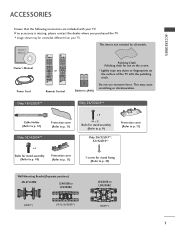
Batteries (AAA) Do not use on the screen. * Lightly wipe any stains or fingerprints on the surface of the TV with your TV. Only 19/22LD3** Only 26/32LD3** Cable Holder (Refer to p. 12) Protection cover (Refer to p. 11) Only 32/42LD4** x 4 Bolts for stand assembly (Refer to p. .../22/26/32LD3**) (42LD4**) 1 If an accessory is not included for all models. This item is missing, please contact the dealer where you purchased the TV. ACCESSORIES ACCESSORIES Ensure that the following accessories are included with the polishing cloth. This may be somewhat different from your...
Batteries (AAA) Do not use on the screen. * Lightly wipe any stains or fingerprints on the surface of the TV with your TV. Only 19/22LD3** Only 26/32LD3** Cable Holder (Refer to p. 12) Protection cover (Refer to p. 11) Only 32/42LD4** x 4 Bolts for stand assembly (Refer to p. .../22/26/32LD3**) (42LD4**) 1 If an accessory is not included for all models. This item is missing, please contact the dealer where you purchased the TV. ACCESSORIES ACCESSORIES Ensure that the following accessories are included with the polishing cloth. This may be somewhat different from your...

Owners Manual
Page 4
... to a desk 10 Not Using the desk-type stand 11 Back Cover for PC Mode 28 WATCHING TV / PROGRAMME CONTROL Remote Control Key Functions 32 Turning on the TV 36 Programme Selection 36 Volume Adjustment 36 Quick Menu 37 On-Screen Menus Selection and Adjustment..... 38 Auto...Indicator 78 Demo Mode 79 Mode Setting 80 CONTENTS CONTENTS ACCESSORIES 1 PREPARATION Front Panel Controls 4 Back Panel Information 6 Stand Installation 9 Attaching the TV to original factory settings)...... 51 AV Mode 52 TO USE A USB DEVICE When connecting the USB device 53 Photo List 55 Music List 59...
... to a desk 10 Not Using the desk-type stand 11 Back Cover for PC Mode 28 WATCHING TV / PROGRAMME CONTROL Remote Control Key Functions 32 Turning on the TV 36 Programme Selection 36 Volume Adjustment 36 Quick Menu 37 On-Screen Menus Selection and Adjustment..... 38 Auto...Indicator 78 Demo Mode 79 Mode Setting 80 CONTENTS CONTENTS ACCESSORIES 1 PREPARATION Front Panel Controls 4 Back Panel Information 6 Stand Installation 9 Attaching the TV to original factory settings)...... 51 AV Mode 52 TO USE A USB DEVICE When connecting the USB device 53 Photo List 55 Music List 59...

Owners Manual
Page 5
... 99 IR Codes 101 External Control Device Setup 102 3 User Mode 83 Infinite Sound 83 SRS TruSurround XT 84 Clear Voice ll 85 Balance 85 TV Speakers On/ Off Setup 86 Selecting Audio Out 87 Audio Reset 88 I/II - NICAM Reception 90 -
... 99 IR Codes 101 External Control Device Setup 102 3 User Mode 83 Infinite Sound 83 SRS TruSurround XT 84 Clear Voice ll 85 Balance 85 TV Speakers On/ Off Setup 86 Selecting Audio Out 87 Audio Reset 88 I/II - NICAM Reception 90 -
Owners Manual
Page 6
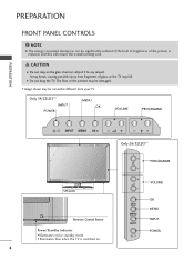
...Control Sensor Power/Standby Indicator • Illuminates red in standby mode. • Illuminates blue when the TV is reduced, and this will reduce the overall running cost. G Do not drag the TV. OK MENU INPUT OK MENU INPUT POWER 4 NOTE G The energy consumed during use can be ...significantly reduced if the level of brightness of glass, or the TV may be damaged. CAUTION G Do not step on . PREPARATION P FRONT PANEL CONTROLS ! I Image shown may fall. It may be somewhat different...
...Control Sensor Power/Standby Indicator • Illuminates red in standby mode. • Illuminates blue when the TV is reduced, and this will reduce the overall running cost. G Do not drag the TV. OK MENU INPUT OK MENU INPUT POWER 4 NOTE G The energy consumed during use can be ...significantly reduced if the level of brightness of glass, or the TV may be damaged. CAUTION G Do not step on . PREPARATION P FRONT PANEL CONTROLS ! I Image shown may fall. It may be somewhat different...
Owners Manual
Page 7
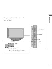
Only 32/42LD4** SPEAKER Remote Control Sensor Power/Standby Indicator • Illuminates red in standby mode. • Illuminates blue when the TV is switched on. P OK MENU INPUT PROGRAMME VOLUME OK MENU INPUT POWER 5 PREPARATION I Image shown may be somewhat different from your TV.
Only 32/42LD4** SPEAKER Remote Control Sensor Power/Standby Indicator • Illuminates red in standby mode. • Illuminates blue when the TV is switched on. P OK MENU INPUT PROGRAMME VOLUME OK MENU INPUT POWER 5 PREPARATION I Image shown may be somewhat different from your TV.

Owners Manual
Page 8
...device to these jacks. 8 Component Input Connect a component video/audio device to these jacks. 4 RS-232C IN PORT Connect to operate the TV on an AC power. ANTENNA ANTENNA IN IN 6 The voltage is used for Service or Hotel mode. 9 Antenna Input Connect RF antenna to...AUDIO COMPONENT IN VIDEOANLT/MEONNONAAUDIO R IN VIDEO AUDIO COMPONENT IN 8 9 1 Power Cord Socket This TV operates on DC power. 8 ANTENNA IN 5 SERVICE ONLY PORT 6 RGB/DVI Audio Input Connect the audio from your TV. ANTENNA IN 9 2 HDMI Input Connect a HDMI signal to this jack. PREPARATION BACK PANEL ...
...device to these jacks. 8 Component Input Connect a component video/audio device to these jacks. 4 RS-232C IN PORT Connect to operate the TV on an AC power. ANTENNA ANTENNA IN IN 6 The voltage is used for Service or Hotel mode. 9 Antenna Input Connect RF antenna to...AUDIO COMPONENT IN VIDEOANLT/MEONNONAAUDIO R IN VIDEO AUDIO COMPONENT IN 8 9 1 Power Cord Socket This TV operates on DC power. 8 ANTENNA IN 5 SERVICE ONLY PORT 6 RGB/DVI Audio Input Connect the audio from your TV. ANTENNA IN 9 2 HDMI Input Connect a HDMI signal to this jack. PREPARATION BACK PANEL ...

Owners Manual
Page 9
Never attempt to operate the TV on a PC. Or DVI(VIDEO)signal to HDMI/DVI port with DVI to HDMI cable. 3 RGB IN Input Connect the output from a PC. 4 RS-232C ... IN 8 ANTENNA IN 9 AUDIO IN 2 (RGB/DVI) RGB IN (PC) VIDEO L/MONO AUDIO R 1 /DVI IN VIDEO AUDIO COMPONENT IN 8 ANTENNA IN 9 1 Power Cord Socket This TV operates on the Specifications page. This port is indicated on an AC power. The voltage is used for Service or Hotel mode. 5 SERVICE ONLY PORT...
Never attempt to operate the TV on a PC. Or DVI(VIDEO)signal to HDMI/DVI port with DVI to HDMI cable. 3 RGB IN Input Connect the output from a PC. 4 RS-232C ... IN 8 ANTENNA IN 9 AUDIO IN 2 (RGB/DVI) RGB IN (PC) VIDEO L/MONO AUDIO R 1 /DVI IN VIDEO AUDIO COMPONENT IN 8 ANTENNA IN 9 1 Power Cord Socket This TV operates on the Specifications page. This port is indicated on an AC power. The voltage is used for Service or Hotel mode. 5 SERVICE ONLY PORT...

Owners Manual
Page 10
... I Image shown may be somewhat different from a PC. 4 RS-232C IN PORT Connect to the RS-232C port on a PC. Never attempt to operate the TV on an AC power. Or DVI(VIDEO)signal to HDMI/DVI port with DVI to the AV OUT socket on the Specifications page. The voltage... these jacks. 8 Antenna Input Connect RF antenna to this jack. 9 USB IN Input Connect USB storage device to this jack. 10 AV Output Connect second TV or monitor to HDMI cable. 3 RGB IN Input Connect the output from your surround sound system. 8 This port is indicated on the...
... I Image shown may be somewhat different from a PC. 4 RS-232C IN PORT Connect to the RS-232C port on a PC. Never attempt to operate the TV on an AC power. Or DVI(VIDEO)signal to HDMI/DVI port with DVI to the AV OUT socket on the Specifications page. The voltage... these jacks. 8 Antenna Input Connect RF antenna to this jack. 9 USB IN Input Connect USB storage device to this jack. 10 AV Output Connect second TV or monitor to HDMI cable. 3 RGB IN Input Connect the output from your surround sound system. 8 This port is indicated on the...
Owners Manual
Page 11
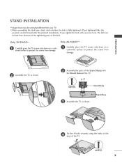
.... I Image shown may be somewhat different from your TV. M4X20 9 Only 19/22LD3** 1 Carefully place the TV screen side down on a cushioned surface to protect the screen from damage. 2 Assemble the TV as shown. M4X20 Stand Body 3 Assemble the TV as shown. 2 Assemble the parts of the Stand ...Body with excessive force, the bolt can tilt forward after the product installation.) If you tighten the bolt with the Stand Base of the TV. PREPARATION STAND INSTALLATION I When assembling the desk type stand, check whether the bolt is fully tightened. (If not tightened fully, the ...
.... I Image shown may be somewhat different from your TV. M4X20 9 Only 19/22LD3** 1 Carefully place the TV screen side down on a cushioned surface to protect the screen from damage. 2 Assemble the TV as shown. M4X20 Stand Body 3 Assemble the TV as shown. 2 Assemble the parts of the Stand ...Body with excessive force, the bolt can tilt forward after the product installation.) If you tighten the bolt with the Stand Base of the TV. PREPARATION STAND INSTALLATION I When assembling the desk type stand, check whether the bolt is fully tightened. (If not tightened fully, the ...

Owners Manual
Page 12
... cushioned surface to protect the screen from falling over, the TV should be securely attached to desk so it cannot be somewhat different from your TV. Tipping, shaking, or rocking the machine may be pulled in the back of the TV. ATTACHING THE TV TO A DESK I Image shown may cause injury. 10 Desk... ! Only 26/32LD3**, 32/42LD4** AC IN 2 Assemble the TV as parts of the product) Stand 3 Fix the 4 bolts securely using the holes in a ...
... cushioned surface to protect the screen from falling over, the TV should be securely attached to desk so it cannot be somewhat different from your TV. Tipping, shaking, or rocking the machine may be pulled in the back of the TV. ATTACHING THE TV TO A DESK I Image shown may cause injury. 10 Desk... ! Only 26/32LD3**, 32/42LD4** AC IN 2 Assemble the TV as parts of the product) Stand 3 Fix the 4 bolts securely using the holes in a ...

Owners Manual
Page 13
... Cover Only 32/42LD4** Insert the Protection Cover into the TV until clicking sound. Only 26/32LD3** Insert the Protection Cover into the TV until clicking sound. 2 Loose the bolts from TV. 3 Detach the Stand from your TV. When installing the wall-mounted unit, use the protection cover.... Only 19/22LD3** 1 Carefully place the TV screen side down on a cushioned surface to the TV as shown. Protection ...
... Cover Only 32/42LD4** Insert the Protection Cover into the TV until clicking sound. Only 26/32LD3** Insert the Protection Cover into the TV until clicking sound. 2 Loose the bolts from TV. 3 Detach the Stand from your TV. When installing the wall-mounted unit, use the protection cover.... Only 19/22LD3** 1 Carefully place the TV screen side down on a cushioned surface to the TV as shown. Protection ...

Owners Manual
Page 14
... 26/32LD3**, 32/42LD4** 1 Connect the cables asACnINecessary. NOTE G Do not use the Cable Management Clip to lift the TV. If the TV is dropped, you may be injured or the TV may be damaged. AC IN AC IN 12 Only 19/22LD3** After Connecting the cables as necessary, install CABLE HOLDER... as shown and bundle the cables. PREPARATION AC IN PREPARATION BACK COVER FOR WIRE ARRANGEMENT I Image shown may be somewhat different from your TV.
... 26/32LD3**, 32/42LD4** 1 Connect the cables asACnINecessary. NOTE G Do not use the Cable Management Clip to lift the TV. If the TV is dropped, you may be injured or the TV may be damaged. AC IN AC IN 12 Only 19/22LD3** After Connecting the cables as necessary, install CABLE HOLDER... as shown and bundle the cables. PREPARATION AC IN PREPARATION BACK COVER FOR WIRE ARRANGEMENT I Image shown may be somewhat different from your TV.

Owners Manual
Page 15
...Security System connector on the monitor's performance. I Adjust the position of time. However, they have no adverse effect on the back panel. The TV is not available for all models. For further information, contact http://www.kensington.com, the internet homepage of the Kensington Security System, refer to...or right direction by 20 degrees to the touch, there may be a small "flicker" when when it for all models. G If the TV feels cold to suit your viewing position. AC IN CABLE MANAGEMENT 13 PREPARATION SWIVEL STAND (Except 19/22LD3**) I Image shown may be somewhat ...
...Security System connector on the monitor's performance. I Adjust the position of time. However, they have no adverse effect on the back panel. The TV is not available for all models. For further information, contact http://www.kensington.com, the internet homepage of the Kensington Security System, refer to...or right direction by 20 degrees to the touch, there may be a small "flicker" when when it for all models. G If the TV feels cold to suit your viewing position. AC IN CABLE MANAGEMENT 13 PREPARATION SWIVEL STAND (Except 19/22LD3**) I Image shown may be somewhat ...
Owners Manual
Page 16
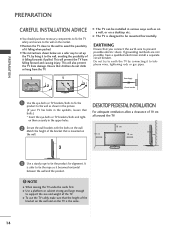
... tie the rope so it falling when pushed. It is designed to be installed in various ways such as shown in the picture. (If your TV has bolts in the upper holes. 2 Secure the wall brackets with the bolts on the wall. PREPARATION PREPARATION CAREFUL INSTALLATION ADVICE A You should purchase...on the wall and on a desktop etc. G Use a platform or cabinet strong and large enough to prevent possible electric shock. NOTE G When moving the TV undo the cords first. A The TV can be mounted horizontally. en them securely in the eyebolts, loosen then bolts.) * Insert the eye-bolts or...
... tie the rope so it falling when pushed. It is designed to be installed in various ways such as shown in the picture. (If your TV has bolts in the upper holes. 2 Secure the wall brackets with the bolts on the wall. PREPARATION PREPARATION CAREFUL INSTALLATION ADVICE A You should purchase...on the wall and on a desktop etc. G Use a platform or cabinet strong and large enough to prevent possible electric shock. NOTE G When moving the TV undo the cords first. A The TV can be mounted horizontally. en them securely in the eyebolts, loosen then bolts.) * Insert the eye-bolts or...

Owners Manual
Page 17
...special wall mount, if you purchase a wall mounting bracket which may cause TV to the floor. G Installing screw type and length depends on the wall mount used . - Further information, refer to incorrect installation: - A LG recommends that wall mounting be of sufficient strength to support the weight of ...screws to surface which supports VESA standard. G LG is to be mounted on a solid wall perpendicular to fall and cause personal injury. - A We recommend that wall mount is not liable for any accidents or damage to property or TV due to the instructions included with the mount....
...special wall mount, if you purchase a wall mounting bracket which may cause TV to the floor. G Installing screw type and length depends on the wall mount used . - Further information, refer to incorrect installation: - A LG recommends that wall mounting be of sufficient strength to support the weight of ...screws to surface which supports VESA standard. G LG is to be mounted on a solid wall perpendicular to fall and cause personal injury. - A We recommend that wall mount is not liable for any accidents or damage to property or TV due to the instructions included with the mount....
Owners Manual
Page 18
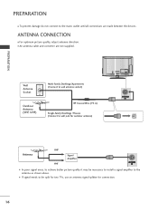
I In poor signal areas, to achieve better picture quality it may be split for two TVs, use an antenna signal splitter for outdoor antenna) Antenna UHF Signal Amplifier VHF VIDEO L(MONO) AUDIO R VARIABLE AUDIO OUT ANTENNA IN I An antenna cable and ...
I In poor signal areas, to achieve better picture quality it may be split for two TVs, use an antenna signal splitter for outdoor antenna) Antenna UHF Signal Amplifier VHF VIDEO L(MONO) AUDIO R VARIABLE AUDIO OUT ANTENNA IN I An antenna cable and ...

Owners Manual
Page 19
I To avoid damaging any equipment, never plug in any power cords until you have finished connecting all equipment. I This section on the TV. HD RECEIVER SETUP Connecting with a component cable 1 Connect the video outputs (Y, PB, PR) of the digital set -top box.) 4 Select Component input source using the ... on the digital set-top box. (Refer to the owner's manual for the digital set -top box to the COMPONENT IN VIDEO jacks on the TV. /DVI IN 2 Connect the audio output of the digital set top box to the COMPONENT IN AUDIO jacks on External Equipment Setup mainly uses diagrams...
I To avoid damaging any equipment, never plug in any power cords until you have finished connecting all equipment. I This section on the TV. HD RECEIVER SETUP Connecting with a component cable 1 Connect the video outputs (Y, PB, PR) of the digital set -top box.) 4 Select Component input source using the ... on the digital set-top box. (Refer to the owner's manual for the digital set -top box to the COMPONENT IN VIDEO jacks on the TV. /DVI IN 2 Connect the audio output of the digital set top box to the COMPONENT IN AUDIO jacks on External Equipment Setup mainly uses diagrams...

Owners Manual
Page 20
... 1 Connect the digital set-top box to HDMI/DVI IN 1, HDMI/DVI IN 2(Except 19/22LD3**) or HDMI IN 3(Only 32/42LD4**) jack on the TV. 2 Turn on the digital set-top box. (Refer to the owner's manual for HDMI cable, and recommend to use the High Speed HDMI Cable. Please...
... 1 Connect the digital set-top box to HDMI/DVI IN 1, HDMI/DVI IN 2(Except 19/22LD3**) or HDMI IN 3(Only 32/42LD4**) jack on the TV. 2 Turn on the digital set-top box. (Refer to the owner's manual for HDMI cable, and recommend to use the High Speed HDMI Cable. Please...

Owners Manual
Page 21
EXTERNAL EQUIPMENT SETUP Connecting with an HDMI to DVI cable 1 Connect the digital set-top box to HDMI/DVI IN 1 jack on the TV. 2 Connect the audio output of the digital set-top box to the AUDIO IN (RGB/DVI) jack on the TV. 3 Turn on the digital set-top box. (Refer to the owner's manual for the digital set-top box.) 4 Select HDMI1input source using the INPUT button on the remote control. AUDIO IN (RGB/DVI) 2 RGB IN (PC) VIDEO /MONO AUD 1 /DVI IN Y PB PR L VIDEO AUDIO COMPONENT IN 1 2 19
EXTERNAL EQUIPMENT SETUP Connecting with an HDMI to DVI cable 1 Connect the digital set-top box to HDMI/DVI IN 1 jack on the TV. 2 Connect the audio output of the digital set-top box to the AUDIO IN (RGB/DVI) jack on the TV. 3 Turn on the digital set-top box. (Refer to the owner's manual for the digital set-top box.) 4 Select HDMI1input source using the INPUT button on the remote control. AUDIO IN (RGB/DVI) 2 RGB IN (PC) VIDEO /MONO AUD 1 /DVI IN Y PB PR L VIDEO AUDIO COMPONENT IN 1 2 19


