
Owners Manual
Page 1
www.lg.com OWNER'S MANUAL LCD TV Please read this manual carefully before operating your set and retain it for future reference.
www.lg.com OWNER'S MANUAL LCD TV Please read this manual carefully before operating your set and retain it for future reference.

Owners Manual
Page 2
HDMI, the HDMI logo and High-Definition Multimedia Interface are trademarks or registered trademarks of HDMI Licensing LLC.
HDMI, the HDMI logo and High-Definition Multimedia Interface are trademarks or registered trademarks of HDMI Licensing LLC.
Owners Manual
Page 3
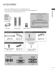
Owner's Manual Power Cord ENERGY AV MODE INPUT SAVING 123 456 789 LIST 0 Q.VIEW MARK FAV RATIO MUTE P PA G E MENU CLEAR VOICE II Q.MENU or OK BACK EXIT ENERGY AV MODE INPUT SAVING 123 456 789 LIST 0 Q.VIEW MARK FAV RATIO MUTE P PA G E MENU Q.MENU OK BACK EXIT Remote Control Polishing Cloth Polishing cloth for use excessive force. Only 19/22LD3** Only 26/32LD3** Cable Holder (Refer to p. 12) Protection cover (Refer to p. 11) Only 32/42LD4** x 4 Bolts for stand assembly (Refer to p. 10) Protection cover (Refer to p. 11) x 8 M4 x 20 Bolts for stand assembly (...
Owner's Manual Power Cord ENERGY AV MODE INPUT SAVING 123 456 789 LIST 0 Q.VIEW MARK FAV RATIO MUTE P PA G E MENU CLEAR VOICE II Q.MENU or OK BACK EXIT ENERGY AV MODE INPUT SAVING 123 456 789 LIST 0 Q.VIEW MARK FAV RATIO MUTE P PA G E MENU Q.MENU OK BACK EXIT Remote Control Polishing Cloth Polishing cloth for use excessive force. Only 19/22LD3** Only 26/32LD3** Cable Holder (Refer to p. 12) Protection cover (Refer to p. 11) Only 32/42LD4** x 4 Bolts for stand assembly (Refer to p. 10) Protection cover (Refer to p. 11) x 8 M4 x 20 Bolts for stand assembly (...

Owners Manual
Page 4
Picture Mode-Preset 71 Manual Picture Adjustment - CONTENTS CONTENTS ACCESSORIES 1 PREPARATION Front Panel Controls 4 Back Panel Information 6 Stand Installation 9 Attaching the TV to a desk 10 Not Using the desk-type stand 11 Back Cover for PC Mode 28 WATCHING TV / PROGRAMME CONTROL Remote Control Key Functions 32 Turning on the TV 36 Programme Selection 36 Volume Adjustment 36 Quick Menu 37 On-Screen Menus Selection and Adjustment..... 38 Auto Programme Tuning 39 Manual Programme Tuning 40 Programme Edit 42 Selecting the Programme List 44 2 PICTURE CONTROL Picture ...
Picture Mode-Preset 71 Manual Picture Adjustment - CONTENTS CONTENTS ACCESSORIES 1 PREPARATION Front Panel Controls 4 Back Panel Information 6 Stand Installation 9 Attaching the TV to a desk 10 Not Using the desk-type stand 11 Back Cover for PC Mode 28 WATCHING TV / PROGRAMME CONTROL Remote Control Key Functions 32 Turning on the TV 36 Programme Selection 36 Volume Adjustment 36 Quick Menu 37 On-Screen Menus Selection and Adjustment..... 38 Auto Programme Tuning 39 Manual Programme Tuning 40 Programme Edit 42 Selecting the Programme List 44 2 PICTURE CONTROL Picture ...

Owners Manual
Page 5
User Mode 83 Infinite Sound 83 SRS TruSurround XT 84 Clear Voice ll 85 Balance 85 TV Speakers On/ Off Setup 86 Selecting Audio Out 87 Audio Reset 88 I/II - Stereo/Dual Reception 89 - Sound Mode 82 Sound Setting Adjustment - Speaker Sound Output Selection 90 On-Screen Menu Language Selection 91 TIME SETTING Clock Setup 92 Auto On/ Off Timer Setting 93 Sleep Timer Setting 93 TELETEXT Switch on/off 94 SIMPLE Text 94 TOP Text 94 FASTEXT 95 Special Teletext Functions 95 APPENDIX Troubleshooting 96 Maintenance 98 Product Specifications 99 IR Codes 101 External ...
User Mode 83 Infinite Sound 83 SRS TruSurround XT 84 Clear Voice ll 85 Balance 85 TV Speakers On/ Off Setup 86 Selecting Audio Out 87 Audio Reset 88 I/II - Stereo/Dual Reception 89 - Sound Mode 82 Sound Setting Adjustment - Speaker Sound Output Selection 90 On-Screen Menu Language Selection 91 TIME SETTING Clock Setup 92 Auto On/ Off Timer Setting 93 Sleep Timer Setting 93 TELETEXT Switch on/off 94 SIMPLE Text 94 TOP Text 94 FASTEXT 95 Special Teletext Functions 95 APPENDIX Troubleshooting 96 Maintenance 98 Product Specifications 99 IR Codes 101 External ...
Owners Manual
Page 6
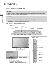
CAUTION G Do not step on . I Image shown may be damaged. Only 19/22LD3** INPUT POWER MENU OK VOLUME PROGRAMME PREPARATION INPUT MENUP OK P P Only 26/32LD3** PROGRAMME P VOLUME SPEAKER Remote Control Sensor Power/Standby Indicator • Illuminates red in standby mode. • Illuminates blue when the TV is reduced, and this will reduce the overall running cost. G Do not drag the TV. It may fall. NOTE G The energy consumed during use can be significantly reduced if the level of brightness of glass, or the TV may break, causing possible injury from your TV. ...
CAUTION G Do not step on . I Image shown may be damaged. Only 19/22LD3** INPUT POWER MENU OK VOLUME PROGRAMME PREPARATION INPUT MENUP OK P P Only 26/32LD3** PROGRAMME P VOLUME SPEAKER Remote Control Sensor Power/Standby Indicator • Illuminates red in standby mode. • Illuminates blue when the TV is reduced, and this will reduce the overall running cost. G Do not drag the TV. It may fall. NOTE G The energy consumed during use can be significantly reduced if the level of brightness of glass, or the TV may break, causing possible injury from your TV. ...
Owners Manual
Page 7
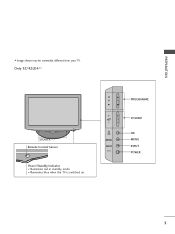
PREPARATION I Image shown may be somewhat different from your TV. P OK MENU INPUT PROGRAMME VOLUME OK MENU INPUT POWER 5 Only 32/42LD4** SPEAKER Remote Control Sensor Power/Standby Indicator • Illuminates red in standby mode. • Illuminates blue when the TV is switched on.
PREPARATION I Image shown may be somewhat different from your TV. P OK MENU INPUT PROGRAMME VOLUME OK MENU INPUT POWER 5 Only 32/42LD4** SPEAKER Remote Control Sensor Power/Standby Indicator • Illuminates red in standby mode. • Illuminates blue when the TV is switched on.

Owners Manual
Page 8
Never attempt to operate the TV on a PC. VIDEO L/MONO AUDIO R 10 USB IN Input Connect USB storage device to HDMI IN. ANTENNA IN 9 2 HDMI Input Connect a HDMI signal to this jack. Or DVI(VIDEO)signal to HDMI/DVI port with DVI to HDMI cable. 3 RGB IN Input Connect the output from a PC. 7 Audio/Video Input Connect audio/video output from an external device to these jacks. 8 Component Input Connect a component video/audio device to these jacks. 4 RS-232C IN PORT Connect to this jack. VIDEO L(MONO) AUDIO R 1 AC-IN K ANTENNA IN Only 19/22LD34* 10 AV IN AV IN PREPARATION Only 19/...
Never attempt to operate the TV on a PC. VIDEO L/MONO AUDIO R 10 USB IN Input Connect USB storage device to HDMI IN. ANTENNA IN 9 2 HDMI Input Connect a HDMI signal to this jack. Or DVI(VIDEO)signal to HDMI/DVI port with DVI to HDMI cable. 3 RGB IN Input Connect the output from a PC. 7 Audio/Video Input Connect audio/video output from an external device to these jacks. 8 Component Input Connect a component video/audio device to these jacks. 4 RS-232C IN PORT Connect to this jack. VIDEO L(MONO) AUDIO R 1 AC-IN K ANTENNA IN Only 19/22LD34* 10 AV IN AV IN PREPARATION Only 19/...

Owners Manual
Page 9
The voltage is used for Service or Hotel mode. 5 SERVICE ONLY PORT 6 RGB/DVI Audio Input Connect the audio from a PC. 7 Audio/Video Input Connect audio/video output from an external device to these jacks. 8 Component Input Connect a component video/audio device to these jacks. 9 Antenna Input Connect RF antenna to this jack. 7 Never attempt to HDMI IN. ANTENNA IN ANTENNA IN PREPARATION AV IN1 AV IN1 VIDEO L(MONO) AUDIO R I Image shown may be somewhat different from yourATNVTE.NNA IN VIDEO L(MONO) AUDIO R Only 26/32LD34* Only 26/32LD33* ANTENNA 10 IN VIDEO L/MONO AUDIO R ...
The voltage is used for Service or Hotel mode. 5 SERVICE ONLY PORT 6 RGB/DVI Audio Input Connect the audio from a PC. 7 Audio/Video Input Connect audio/video output from an external device to these jacks. 8 Component Input Connect a component video/audio device to these jacks. 9 Antenna Input Connect RF antenna to this jack. 7 Never attempt to HDMI IN. ANTENNA IN ANTENNA IN PREPARATION AV IN1 AV IN1 VIDEO L(MONO) AUDIO R I Image shown may be somewhat different from yourATNVTE.NNA IN VIDEO L(MONO) AUDIO R Only 26/32LD34* Only 26/32LD33* ANTENNA 10 IN VIDEO L/MONO AUDIO R ...

Owners Manual
Page 10
Or DVI(VIDEO)signal to HDMI/DVI port with DVI to HDMI cable. 3 RGB IN Input Connect the output from an external device to these jacks. 7 Component Input Connect a component video/audio device to these jacks. 8 Antenna Input Connect RF antenna to this jack. 9 USB IN Input Connect USB storage device to this jack. 10 AV Output Connect second TV or monitor to your TV. Variable Audio Output Connect an external amplifier or add a subwoofer to the AV OUT socket on a PC. Never attempt to operate the TV on DC power. 2 HDMI Input Connect a HDMI signal to the RS-232C port on the TV. ...
Or DVI(VIDEO)signal to HDMI/DVI port with DVI to HDMI cable. 3 RGB IN Input Connect the output from an external device to these jacks. 7 Component Input Connect a component video/audio device to these jacks. 8 Antenna Input Connect RF antenna to this jack. 9 USB IN Input Connect USB storage device to this jack. 10 AV Output Connect second TV or monitor to your TV. Variable Audio Output Connect an external amplifier or add a subwoofer to the AV OUT socket on a PC. Never attempt to operate the TV on DC power. 2 HDMI Input Connect a HDMI signal to the RS-232C port on the TV. ...
Owners Manual
Page 11
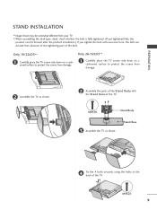
Only 19/22LD3** 1 Carefully place the TV screen side down on a cushioned surface to protect the screen from damage. Only 26/32LD3** 1 Carefully place the TV screen side down on a cushioned surface to protect the screen from damage. 2 Assemble the TV as shown. M4X20 Stand Body 3 Assemble the TV as shown. 2 Assemble the parts of the Stand Body with excessive force, the bolt can deviate from your TV. M4X20 9 Stand Base 4 Fix the 4 bolts securely using the holes in the back of the TV. I Image shown may be somewhat different from abrasion of the tightening part of the ...
Only 19/22LD3** 1 Carefully place the TV screen side down on a cushioned surface to protect the screen from damage. Only 26/32LD3** 1 Carefully place the TV screen side down on a cushioned surface to protect the screen from damage. 2 Assemble the TV as shown. M4X20 Stand Body 3 Assemble the TV as shown. 2 Assemble the parts of the Stand Body with excessive force, the bolt can deviate from your TV. M4X20 9 Stand Base 4 Fix the 4 bolts securely using the holes in the back of the TV. I Image shown may be somewhat different from abrasion of the tightening part of the ...

Owners Manual
Page 12
PREPARATION PREPARATION Only 32/42LD4** 1 Carefully place the TV screen side down on a cushioned surface to desk so it cannot be pulled in the back of the TV. Use only an attached screw. CABLE MANAGEMENT 1-Screw (provided as shown. ATTACHING THE TV TO A DESK I Image shown may cause injury. 10 Desk ! Only 26/32LD3**, 32/42LD4** AC IN 2 Assemble the TV as parts of the product) Stand 3 Fix the 4 bolts securely using the holes in a forward/backward direction, potentially causing injury or damaging the product. Tipping, shaking, or rocking the machine may be securely ...
PREPARATION PREPARATION Only 32/42LD4** 1 Carefully place the TV screen side down on a cushioned surface to desk so it cannot be pulled in the back of the TV. Use only an attached screw. CABLE MANAGEMENT 1-Screw (provided as shown. ATTACHING THE TV TO A DESK I Image shown may cause injury. 10 Desk ! Only 26/32LD3**, 32/42LD4** AC IN 2 Assemble the TV as parts of the product) Stand 3 Fix the 4 bolts securely using the holes in a forward/backward direction, potentially causing injury or damaging the product. Tipping, shaking, or rocking the machine may be securely ...

Owners Manual
Page 13
Protection Cover Only 32/42LD4** Insert the Protection Cover into the TV until clicking sound. Only 26/32LD3** Insert the Protection Cover into the TV until clicking sound. 2 Loose the bolts from TV. 3 Detach the Stand from T V. Protection Cover 11 Protection Cover 4 After removing the protection paper from the protection cover, adhere it to protect the screen from your TV. PREPARATION NOT USING THE DESK-TYPE STAND I Image shown may be somewhat different from damage. When installing the wall-mounted unit, use the protection cover. Only 19/22LD3** 1 Carefully place the TV ...
Protection Cover Only 32/42LD4** Insert the Protection Cover into the TV until clicking sound. Only 26/32LD3** Insert the Protection Cover into the TV until clicking sound. 2 Loose the bolts from TV. 3 Detach the Stand from T V. Protection Cover 11 Protection Cover 4 After removing the protection paper from the protection cover, adhere it to protect the screen from your TV. PREPARATION NOT USING THE DESK-TYPE STAND I Image shown may be somewhat different from damage. When installing the wall-mounted unit, use the protection cover. Only 19/22LD3** 1 Carefully place the TV ...

Owners Manual
Page 14
To connect additional equipment, see the External Equipment Setup section of the manual. AC IN AC IN 12 AC IN AC IN AC IN Cable Management Clip 3 Fit the Cable Management Clip as shown and manage the cables. ACIN - PREPARATION AC IN PREPARATION BACK COVER FOR WIRE ARRANGEMENT I Image shown may be somewhat different from your TV. Only 26/32LD3**, 32/42LD4** 1 Connect the cables asACnINecessary. NOTE G Do not use the Cable Management Clip to lift the TV. AC-IN K AC-IN K AC IN AC IN Cable Holder 2 Open the Cable Management Clip as shown. If the TV is dropped, you ...
To connect additional equipment, see the External Equipment Setup section of the manual. AC IN AC IN 12 AC IN AC IN AC IN Cable Management Clip 3 Fit the Cable Management Clip as shown and manage the cables. ACIN - PREPARATION AC IN PREPARATION BACK COVER FOR WIRE ARRANGEMENT I Image shown may be somewhat different from your TV. Only 26/32LD3**, 32/42LD4** 1 Connect the cables asACnINecessary. NOTE G Do not use the Cable Management Clip to lift the TV. AC-IN K AC-IN K AC IN AC IN Cable Holder 2 Open the Cable Management Clip as shown. If the TV is dropped, you ...

Owners Manual
Page 15
I Image shown may be a small "flicker" when when it for long periods of the panel in various ways for all models. For further information, contact http://www.kensington.com, the internet homepage of the Kensington Security System, refer to suit your TV. G If the TV feels cold to the touch, there may be somewhat different from your finger(s) against it is nothing wrong with a Kensington Security System connector on the back panel. This is normal, there is turned on. Doing so may be somewhat different from your viewing position. POSITIONING YOUR DISPLAY (Only 19/22LD3**) I...
I Image shown may be a small "flicker" when when it for long periods of the panel in various ways for all models. For further information, contact http://www.kensington.com, the internet homepage of the Kensington Security System, refer to suit your TV. G If the TV feels cold to the touch, there may be somewhat different from your finger(s) against it is nothing wrong with a Kensington Security System connector on the back panel. This is normal, there is turned on. Doing so may be somewhat different from your viewing position. POSITIONING YOUR DISPLAY (Only 19/22LD3**) I...
Owners Manual
Page 16
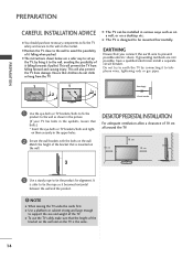
Ensure that is the same. 14 EARTHING Ensure that the height of the bracket on the wall and on the TV is mounted on the wall. If grounding methods are a safer way to set up the TV, by connecting it to telephone wires, lightening rods or gas pipes. 1 1 2 2 Power Supply Circuit breaker 1 Use the eye-bolts or TV brackets/bolts to fix the product to avoid the possibility of it becomes horizontal between the wall and the product. ! NOTE G When moving the TV undo the cords first. A The TV is safer to the wall, avoiding the possibility of it falling when pushed. Do not try ...
Ensure that is the same. 14 EARTHING Ensure that the height of the bracket on the wall and on the TV is mounted on the wall. If grounding methods are a safer way to set up the TV, by connecting it to telephone wires, lightening rods or gas pipes. 1 1 2 2 Power Supply Circuit breaker 1 Use the eye-bolts or TV brackets/bolts to fix the product to avoid the possibility of it becomes horizontal between the wall and the product. ! NOTE G When moving the TV undo the cords first. A The TV is safer to the wall, avoiding the possibility of it falling when pushed. Do not try ...

Owners Manual
Page 17
... G Should use of screws to surface which supports VESA standard. G Installing screw type and length depends on the wall mount used . - G LG is to be performed by a qualified professional installer. 10 cm 10 cm 10 cm 10 cm 10 cm A B AC IN CABLE MANAGEMENT Model ...Screw Quantity 100 * 100 M4 4 100 * 100 M4 4 200 * 100 M4 4 200 * 100 M4 4 200 * 100 M4 4 200 * 200 M6 4 ! Incorrect fastening of a LG Brand wall mounting bracket when mounting the TV to a wall. PREPARATION WALL MOUNT: HORIZONTAL INSTALLATION A We recommend the use a special wall mount, if you purchase...
... G Should use of screws to surface which supports VESA standard. G Installing screw type and length depends on the wall mount used . - G LG is to be performed by a qualified professional installer. 10 cm 10 cm 10 cm 10 cm 10 cm A B AC IN CABLE MANAGEMENT Model ...Screw Quantity 100 * 100 M4 4 100 * 100 M4 4 200 * 100 M4 4 200 * 100 M4 4 200 * 100 M4 4 200 * 200 M6 4 ! Incorrect fastening of a LG Brand wall mounting bracket when mounting the TV to a wall. PREPARATION WALL MOUNT: HORIZONTAL INSTALLATION A We recommend the use a special wall mount, if you purchase...
Owners Manual
Page 18
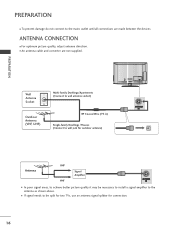
I If signal needs to be necessary to install a signal amplifier to the antenna as shown above. I An antenna cable and converter are made between the devices. Wall Antenna Socket Outdoor Antenna (VHF, UHF) AC IN CABLE MANAGEMENT Multi-family Dwellings/Apartments (Connect to wall antenna socket) VIDEO L(MONO) AUDIO R RF Coaxial Wire (75 Ω) VARIABLE AUDIO OUT ANTENNA IN Single-family Dwellings /Houses (Connect to wall jack for outdoor antenna) Antenna UHF Signal Amplifier VHF VIDEO L(MONO) AUDIO R VARIABLE AUDIO OUT ANTENNA IN I In poor signal areas, to achieve ...
I If signal needs to be necessary to install a signal amplifier to the antenna as shown above. I An antenna cable and converter are made between the devices. Wall Antenna Socket Outdoor Antenna (VHF, UHF) AC IN CABLE MANAGEMENT Multi-family Dwellings/Apartments (Connect to wall antenna socket) VIDEO L(MONO) AUDIO R RF Coaxial Wire (75 Ω) VARIABLE AUDIO OUT ANTENNA IN Single-family Dwellings /Houses (Connect to wall jack for outdoor antenna) Antenna UHF Signal Amplifier VHF VIDEO L(MONO) AUDIO R VARIABLE AUDIO OUT ANTENNA IN I In poor signal areas, to achieve ...

Owners Manual
Page 19
VIDEO AUDIO COMPONENT IN ANTENNA IN 3 Turn on the digital set-top box. (Refer to the owner's manual for the 26/32LD33* models. HD RECEIVER SETUP Connecting with a component cable 1 Connect the video outputs (Y, PB, PR) of the digital set top box to the COMPONENT IN AUDIO jacks on the remote control. 1 2 Signal 480i / 576i 480p / 576p 720p / 1080i 1080p Component HDMI O X O O O O O O (50 Hz / 60 Hz only) (24 Hz / 30 Hz / 50 Hz / 60 Hz) 17 I To avoid damaging any equipment, never plug in any power cords until you have finished connecting all equipment. EXTERNAL ...
VIDEO AUDIO COMPONENT IN ANTENNA IN 3 Turn on the digital set-top box. (Refer to the owner's manual for the 26/32LD33* models. HD RECEIVER SETUP Connecting with a component cable 1 Connect the video outputs (Y, PB, PR) of the digital set top box to the COMPONENT IN AUDIO jacks on the remote control. 1 2 Signal 480i / 576i 480p / 576p 720p / 1080i 1080p Component HDMI O X O O O O O O (50 Hz / 60 Hz only) (24 Hz / 30 Hz / 50 Hz / 60 Hz) 17 I To avoid damaging any equipment, never plug in any power cords until you have finished connecting all equipment. EXTERNAL ...

Owners Manual
Page 20
AUDIO (RGB/D 2 RGB IN (PC) VIDEO /MONO 1 /DVI IN Y PB PR L VIDEO A COMPONENT I 1 18 EXTERNAL EQUIPMENT SETUP EXTERNAL EQUIPMENT SETUP Connecting a set-top box with an HDMI cable 1 Connect the digital set-top box to HDMI/DVI IN 1, HDMI/DVI IN 2(Except 19/22LD3**) or HDMI IN 3(Only 32/42LD4**) jack on the TV. 2 Turn on the digital set -top box.) 3 Select HDMI1, HDMI2(Except 19/22LD3**) or HDMI3(Only 32/42LD4**) input source using the INPUT button on the remote control. ! If the HDMI cables are not High Speed HDMI Cable, flickering or no screen display can result. G ...
AUDIO (RGB/D 2 RGB IN (PC) VIDEO /MONO 1 /DVI IN Y PB PR L VIDEO A COMPONENT I 1 18 EXTERNAL EQUIPMENT SETUP EXTERNAL EQUIPMENT SETUP Connecting a set-top box with an HDMI cable 1 Connect the digital set-top box to HDMI/DVI IN 1, HDMI/DVI IN 2(Except 19/22LD3**) or HDMI IN 3(Only 32/42LD4**) jack on the TV. 2 Turn on the digital set -top box.) 3 Select HDMI1, HDMI2(Except 19/22LD3**) or HDMI3(Only 32/42LD4**) input source using the INPUT button on the remote control. ! If the HDMI cables are not High Speed HDMI Cable, flickering or no screen display can result. G ...