
Owners Manual
Page 7
... Mounting 19 Desktop Pedestal Installation 19 Antenna or Cable Connection 20 EXTERNAL EQUIPMENT SETUP HD Receiver Setup 21 DVD Setup 24 VCR Setup 26 Other A/V Source Setup 28 Digital Audio Output 28 PC Setup 29 WATCHING TV / CHANNEL CONTROL Remote Control Functions 32 Turning On TV 34 Channel Selection 34 Volume Adjustment 34 On-Screen Menus Selection 35 Channel...
... Mounting 19 Desktop Pedestal Installation 19 Antenna or Cable Connection 20 EXTERNAL EQUIPMENT SETUP HD Receiver Setup 21 DVD Setup 24 VCR Setup 26 Other A/V Source Setup 28 Digital Audio Output 28 PC Setup 29 WATCHING TV / CHANNEL CONTROL Remote Control Functions 32 Turning On TV 34 Channel Selection 34 Volume Adjustment 34 On-Screen Menus Selection 35 Channel...

Owners Manual
Page 8
Some minute dot defects may be visible on surface of mercury. User must be carried out in this product with TV. LCD TV PLASMA TV Owner's Manual http://www.lgusa.com www.lg.ca Copyright© 2007 LGE, All Rights Reserved. PIP CH SWAP + DVD VCR PIP INPUT INFO EXIT CC MENU... RATIO SAP ENTER VOL TIMER MUTE 2 5 3 6 CH PAGE 9 BAFCLKASH 1.5V 1.5V Owner's Manual, Setup & Operation Guide for Commercial Mode CD Manual...
Some minute dot defects may be visible on surface of mercury. User must be carried out in this product with TV. LCD TV PLASMA TV Owner's Manual http://www.lgusa.com www.lg.ca Copyright© 2007 LGE, All Rights Reserved. PIP CH SWAP + DVD VCR PIP INPUT INFO EXIT CC MENU... RATIO SAP ENTER VOL TIMER MUTE 2 5 3 6 CH PAGE 9 BAFCLKASH 1.5V 1.5V Owner's Manual, Setup & Operation Guide for Commercial Mode CD Manual...

Owners Manual
Page 15
BOLT CABLE HOLDER NOTE G Do not hold the CABLE MANAGEMENT when moving the product. - To connect an additional equipment, see the EXTERNAL EQUIPMENT SETUP section. Secure the power cable with both hands and pull it backward. PREPARATION BACK COVER FOR WIRE ARRANGEMENT ■ Here shown may be somewhat ... the CABLE MANAGEMENT G Hold the CABLE MANAGEMENT with the PROTECTIVE BRACKET and the screw as shown. It will help prevent the power cable from your TV. (This feature is dropped, you may be injured or the product may be broken. If the product is not available for all models.) 1 ...
BOLT CABLE HOLDER NOTE G Do not hold the CABLE MANAGEMENT when moving the product. - To connect an additional equipment, see the EXTERNAL EQUIPMENT SETUP section. Secure the power cable with both hands and pull it backward. PREPARATION BACK COVER FOR WIRE ARRANGEMENT ■ Here shown may be somewhat ... the CABLE MANAGEMENT G Hold the CABLE MANAGEMENT with the PROTECTIVE BRACKET and the screw as shown. It will help prevent the power cable from your TV. (This feature is dropped, you may be injured or the product may be broken. If the product is not available for all models.) 1 ...

Owners Manual
Page 16
PROTECTIVE BRACKET BOLT CABLE HOLDER 14 It will help prevent the power cable from your TV. (This feature is not available for all models.) 1 To separate the CABLE HOLDER, loosen the bolt installed the set. 2 Connect the cables as shown. PREPARATION PREPARATION BACK COVER FOR WIRE ARRANGEMENT ■ Here shown may be somewhat different from being removed by accident. 3 Install the CABLE HOLDER as necessary. To connect an additional equipment, see the EXTERNAL EQUIPMENT SETUP section. Secure the power cable with the PROTECTIVE BRACKET and the screw as shown.
PROTECTIVE BRACKET BOLT CABLE HOLDER 14 It will help prevent the power cable from your TV. (This feature is not available for all models.) 1 To separate the CABLE HOLDER, loosen the bolt installed the set. 2 Connect the cables as shown. PREPARATION PREPARATION BACK COVER FOR WIRE ARRANGEMENT ■ Here shown may be somewhat different from being removed by accident. 3 Install the CABLE HOLDER as necessary. To connect an additional equipment, see the EXTERNAL EQUIPMENT SETUP section. Secure the power cable with the PROTECTIVE BRACKET and the screw as shown.

Owners Manual
Page 17
... additional equipment, see the EXTERNAL EQUIPMENT SETUP section. 45° 2 Connect the cables as shown. Hold the CABLE MANAGEMENT CLIP with both hands and pull it as shown and bundle the cables. 3 Install the CABLE MANAGEMENT as necessary. If your TV has CABLE HOLDER, fix it upward.... the CABLE MANAGEMENT CLIP G First, press the cable management. If the TV is dropped, you may be injured or the product may be broken. 15 To connect additional equipment, see the EXTERNAL EQUIPMENT SETUP section. 2 Install the CABLE MANAGEMENT CLIP as necessary. PREPARATION 42PX8DC 1 ...
... additional equipment, see the EXTERNAL EQUIPMENT SETUP section. 45° 2 Connect the cables as shown. Hold the CABLE MANAGEMENT CLIP with both hands and pull it as shown and bundle the cables. 3 Install the CABLE MANAGEMENT as necessary. If your TV has CABLE HOLDER, fix it upward.... the CABLE MANAGEMENT CLIP G First, press the cable management. If the TV is dropped, you may be injured or the product may be broken. 15 To connect additional equipment, see the EXTERNAL EQUIPMENT SETUP section. 2 Install the CABLE MANAGEMENT CLIP as necessary. PREPARATION 42PX8DC 1 ...

Owners Manual
Page 23
...to use picture for the digital set-top box.) ■ Select Component input source with using the INPUT button on the set. HD RECEIVER SETUP This TV can receive Digital Over-the-air/Cable signals without an external digital set-top box. Match the jack colors (Y = green, PB = blue...jacks on the digital set-top box. (Refer to the owner's manual for LCD TV models. HDMI/DVI IN 1(DVI) 1 2 DIGITAL AUDIO OUT (OPTICAL) 2 M.P.I. However, if you have finished connecting all equipment. ■ This part of external equipment setup mainly use ■ Turn on the set. 2. RJP RFACE VIDEO AUDIO ...
...to use picture for the digital set-top box.) ■ Select Component input source with using the INPUT button on the set. HD RECEIVER SETUP This TV can receive Digital Over-the-air/Cable signals without an external digital set-top box. Match the jack colors (Y = green, PB = blue...jacks on the digital set-top box. (Refer to the owner's manual for LCD TV models. HDMI/DVI IN 1(DVI) 1 2 DIGITAL AUDIO OUT (OPTICAL) 2 M.P.I. However, if you have finished connecting all equipment. ■ This part of external equipment setup mainly use ■ Turn on the set. 2. RJP RFACE VIDEO AUDIO ...

Owners Manual
Page 24
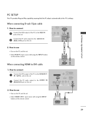
... the set the output resolution appropriately. How to connect 1 Connect the digital set-top box to set . 2 No separated audio connection is necessary. EXTERNAL EQUIPMENT SETUP EXTERNAL EQUIPMENT SETUP When connecting HDMI cable 1.
... the set the output resolution appropriately. How to connect 1 Connect the digital set-top box to set . 2 No separated audio connection is necessary. EXTERNAL EQUIPMENT SETUP EXTERNAL EQUIPMENT SETUP When connecting HDMI cable 1.

Owners Manual
Page 25
... RGB IN RJP INTERFACE 1 VIDEO AUDIO COMPONENT IN S-VIDEO (MONO) AUDIO AV IN 1 VIDEO SPEAKER AUDIO OUT IN 8 (RGB, DVI) 2 DVI-DTV OUTPUT L R 1. EXTERNAL EQUIPMENT SETUP When connecting HDMI to the AUDIO IN (RGB,DVI) jack on the remote control. 23 How to connect 1 Connect the DVI output of the digital...
... RGB IN RJP INTERFACE 1 VIDEO AUDIO COMPONENT IN S-VIDEO (MONO) AUDIO AV IN 1 VIDEO SPEAKER AUDIO OUT IN 8 (RGB, DVI) 2 DVI-DTV OUTPUT L R 1. EXTERNAL EQUIPMENT SETUP When connecting HDMI to the AUDIO IN (RGB,DVI) jack on the remote control. 23 How to connect 1 Connect the DVI output of the digital...

Owners Manual
Page 26
... ( ) COMPONENT IN Component Input ports To get better picture quality, connect a DVD player to the DVD player's manual for operating instructions. Component ports on the TV Y Y Video output ports Y on the DVD player, insert a DVD. How to the 2 COMPONENT IN AUDIO jacks on the set . 2. Y PB PR L R Connect the ... (Y, PB, PR) of the DVD to use ■ Turn on DVD player Y Y PB PR PB PR B-Y R-Y Cb Cr Pb Pr 24 EXTERNAL EQUIPMENT SETUP EXTERNAL EQUIPMENT SETUP DVD SETUP When connecting Component cable 1. Match the jack colors (Y = green, PB = blue, and PR = red).
... ( ) COMPONENT IN Component Input ports To get better picture quality, connect a DVD player to the DVD player's manual for operating instructions. Component ports on the TV Y Y Video output ports Y on the DVD player, insert a DVD. How to the 2 COMPONENT IN AUDIO jacks on the set . 2. Y PB PR L R Connect the ... (Y, PB, PR) of the DVD to use ■ Turn on DVD player Y Y PB PR PB PR B-Y R-Y Cb Cr Pb Pr 24 EXTERNAL EQUIPMENT SETUP EXTERNAL EQUIPMENT SETUP DVD SETUP When connecting Component cable 1. Match the jack colors (Y = green, PB = blue, and PR = red).

Owners Manual
Page 27
...'s manual for operating instructions. 1 2 GITAL UDIO OUT RESET TICAL) M.P.I. HDMI supports both audio and video. 2. When connecting with an S-Video cable 1. S-VIDEO AUDIO L R EXTERNAL EQUIPMENT SETUP 2 Connect the audio outputs of the DVD to the AUDIO input jacks on the set . 2. How to connect 1 Connect the S-VIDEO output of the DVD...
...'s manual for operating instructions. 1 2 GITAL UDIO OUT RESET TICAL) M.P.I. HDMI supports both audio and video. 2. When connecting with an S-Video cable 1. S-VIDEO AUDIO L R EXTERNAL EQUIPMENT SETUP 2 Connect the audio outputs of the DVD to the AUDIO input jacks on the set . 2. How to connect 1 Connect the S-VIDEO output of the DVD...

Owners Manual
Page 28
EXTERNAL EQUIPMENT SETUP EXTERNAL EQUIPMENT SETUP VCR SETUP ■ To avoid picture noise (interference), leave an adequate distance between the VCR and TV. ■ Use the ISM feature in the Option menu to avoid having a fixed image remain on the screen for a long period of the screen may...an antenna 1 S-VIDEO VIDEO L R ANT OUT OUTPUT SWITCH ANT IN Wall Jack 2 Antenna ANTENNA IN M.P.I. 1. the fixed images on the sides of time. (Only Plasma TV model). How to connect 1 Connect the RF antenna out socket of the VCR to the Antenna socket on the VCR. (Refer to all manufactures and...
EXTERNAL EQUIPMENT SETUP EXTERNAL EQUIPMENT SETUP VCR SETUP ■ To avoid picture noise (interference), leave an adequate distance between the VCR and TV. ■ Use the ISM feature in the Option menu to avoid having a fixed image remain on the screen for a long period of the screen may...an antenna 1 S-VIDEO VIDEO L R ANT OUT OUTPUT SWITCH ANT IN Wall Jack 2 Antenna ANTENNA IN M.P.I. 1. the fixed images on the sides of time. (Only Plasma TV model). How to connect 1 Connect the RF antenna out socket of the VCR to the Antenna socket on the VCR. (Refer to all manufactures and...
Owners Manual
Page 29
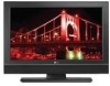
... at the same time. CAUTION G Do not connect to normal composite (RCA cable) input. When connecting with a RCA cable ANT IN S-VIDEO L R VIDEO EXTERNAL EQUIPMENT SETUP 1. NOTE G The picture quality is improved: compared to both Video and the S-Video cables, only the S-Video will work. 27 Match the jack colors (Video... PLAY on the VCR. (Refer to the AUDIO input jacks on the remote control. ■ If connected to connect 1 Connect the AUDIO/VIDEO jacks between TV and VCR. How to AV IN2, select A V 2 input source.
... at the same time. CAUTION G Do not connect to normal composite (RCA cable) input. When connecting with a RCA cable ANT IN S-VIDEO L R VIDEO EXTERNAL EQUIPMENT SETUP 1. NOTE G The picture quality is improved: compared to both Video and the S-Video cables, only the S-Video will work. 27 Match the jack colors (Video... PLAY on the VCR. (Refer to the AUDIO input jacks on the remote control. ■ If connected to connect 1 Connect the AUDIO/VIDEO jacks between TV and VCR. How to AV IN2, select A V 2 input source.
Owners Manual
Page 30
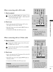
... Output (Optical) port. 1. Looking at the laser beam may damage your vision. 28 EXTERNAL EQUIPMENT SETUP EXTERNAL EQUIPMENT SETUP OTHER A/V SOURCE SETUP 1. Match the jack colors. (Video = yellow, Audio Left = white, and Audio Right = ...red) Camcorder Video Game Set VIDEO L R 2. S-VIDEO 1 VIDEO L/MONO AUDIO R AV IN 2 DIGITAL AUDIO OUTPUT i.e) 32/37/42LC5DC*, 32/37/42LC50C*, 42LB5DC, 42LB50C Send the TV's audio to connect 1 Connect the AUDIO/VIDEO jacks between TV...
... Output (Optical) port. 1. Looking at the laser beam may damage your vision. 28 EXTERNAL EQUIPMENT SETUP EXTERNAL EQUIPMENT SETUP OTHER A/V SOURCE SETUP 1. Match the jack colors. (Video = yellow, Audio Left = white, and Audio Right = ...red) Camcorder Video Game Set VIDEO L R 2. S-VIDEO 1 VIDEO L/MONO AUDIO R AV IN 2 DIGITAL AUDIO OUTPUT i.e) 32/37/42LC5DC*, 32/37/42LC50C*, 42LB5DC, 42LB50C Send the TV's audio to connect 1 Connect the AUDIO/VIDEO jacks between TV...
Owners Manual
Page 31
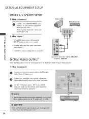
...; Turn on the PC and the set. ■ Select RGB-PC input source with using the INPUT button on the remote control. EXTERNAL EQUIPMENT SETUP PC SETUP This TV provides Plug and Play capability, meaning that the PC adjusts automatically to use ( ) 1 ■ Turn on the PC and the set . HDMI/DVI IN... to the AUDIO IN 2 (RGB/DVI) jack on the set . How to DVI cable RGB OUTPUT AUDIO 1. When connecting D-sub 15pin cable 1. How to the TV's settings.
...; Turn on the PC and the set. ■ Select RGB-PC input source with using the INPUT button on the remote control. EXTERNAL EQUIPMENT SETUP PC SETUP This TV provides Plug and Play capability, meaning that the PC adjusts automatically to use ( ) 1 ■ Turn on the PC and the set . HDMI/DVI IN... to the AUDIO IN 2 (RGB/DVI) jack on the set . How to DVI cable RGB OUTPUT AUDIO 1. When connecting D-sub 15pin cable 1. How to the TV's settings.

Owners Manual
Page 32
G Avoid keeping a fixed image on the screen for Horizontal and Vertical frequencies is clear. EXTERNAL EQUIPMENT SETUP Supported Display Specifications (RGB/HDMI1-PC) Resolution Horizontal Vertical Frequency(KHz) Frequency(Hz) 640x350 31.469 70.08 640x480 31.469 37...., vertical pattern, contrast or brightness in use. G Check the image on the screen. The fixed image may become permanently imprinted on your TV. EXTERNAL EQUIPMENT SETUP NOTES G Depending on the graphics card, DOS mode may not work if a HDMI to another rate or adjust the brightness and contrast on...
G Avoid keeping a fixed image on the screen for Horizontal and Vertical frequencies is clear. EXTERNAL EQUIPMENT SETUP Supported Display Specifications (RGB/HDMI1-PC) Resolution Horizontal Vertical Frequency(KHz) Frequency(Hz) 640x350 31.469 70.08 640x480 31.469 37...., vertical pattern, contrast or brightness in use. G Check the image on the screen. The fixed image may become permanently imprinted on your TV. EXTERNAL EQUIPMENT SETUP NOTES G Depending on the graphics card, DOS mode may not work if a HDMI to another rate or adjust the brightness and contrast on...

Owners Manual
Page 33
EXTERNAL EQUIPMENT SETUP * 42LB5DC, 42LB50C Supported Display Specifications (RGB/HDMI1-PC) Resolution 640x350 (RGB only) Horizontal Vertical Frequency(KHz) Frequency(Hz) 31.469 70.08 640x480 31.469 ...
EXTERNAL EQUIPMENT SETUP * 42LB5DC, 42LB50C Supported Display Specifications (RGB/HDMI1-PC) Resolution 640x350 (RGB only) Horizontal Vertical Frequency(KHz) Frequency(Hz) 31.469 70.08 640x480 31.469 ...

Owners Manual
Page 37
... then use D E F G button to display the available menus. Block Downloadable Rating For Canada Lock System Set Password Block Channel TV Rating-English TV Rating-French Aux. SETUP SETUP VIDEO AUDIO TIME OPTION SCREEN LOCK EZ Scan Manual Scan Channel Edit DTV Signal Channel Label VIDEO... SETUP VIDEO AUDIO TIME OPTION SCREEN LOCK EZ Picture Color Temperature XD Advanced Reset AUDIO SETUP Audio Language VIDEO EZ SoundRite AUDIO EZ Sound TIME Balance 0 OPTION TV Speakers SCREEN LOCK WATCHING TV / CHANNEL CONTROL LOCK For USA SETUP VIDEO AUDIO TIME ...
... then use D E F G button to display the available menus. Block Downloadable Rating For Canada Lock System Set Password Block Channel TV Rating-English TV Rating-French Aux. SETUP SETUP VIDEO AUDIO TIME OPTION SCREEN LOCK EZ Scan Manual Scan Channel Edit DTV Signal Channel Label VIDEO... SETUP VIDEO AUDIO TIME OPTION SCREEN LOCK EZ Picture Color Temperature XD Advanced Reset AUDIO SETUP Audio Language VIDEO EZ SoundRite AUDIO EZ Sound TIME Balance 0 OPTION TV Speakers SCREEN LOCK WATCHING TV / CHANNEL CONTROL LOCK For USA SETUP VIDEO AUDIO TIME ...

Owners Manual
Page 38
WATCHING TV / CHANNEL CONTROL WATCHING TV /CHANNEL CONTROL CHANNEL SETUP Auto Scan (EZ Scan) Automatically finds all channels available through antenna or cable inputs, and stores them in memory on . 1 Press the MENU button and then use D or E button to select the SETUP menu. 2 Press the G button and then ...LOCK EZ Scan Manual Scan Channel Edit DTV Signal Channel Label G Processing EZ scan... SETUP VIDEO AUDIO TIME OPTION SCREEN LOCK EZ Scan Manual Scan Channel Edit DTV Signal Channel Label SETUP VIDEO AUDIO TIME OPTION SCREEN LOCK EZ Scan Manual Scan Channel Edit DTV Signal Channel...
WATCHING TV / CHANNEL CONTROL WATCHING TV /CHANNEL CONTROL CHANNEL SETUP Auto Scan (EZ Scan) Automatically finds all channels available through antenna or cable inputs, and stores them in memory on . 1 Press the MENU button and then use D or E button to select the SETUP menu. 2 Press the G button and then ...LOCK EZ Scan Manual Scan Channel Edit DTV Signal Channel Label G Processing EZ scan... SETUP VIDEO AUDIO TIME OPTION SCREEN LOCK EZ Scan Manual Scan Channel Edit DTV Signal Channel Label SETUP VIDEO AUDIO TIME OPTION SCREEN LOCK EZ Scan Manual Scan Channel Edit DTV Signal Channel...

Owners Manual
Page 39
... AUDIO TIME OPTION SCREEN LOCK EZ Scan Manual Scan Channel Edit DTV Signal Channel Label G Channel Type Number ANALOG 2 SETUP VIDEO AUDIO TIME OPTION SCREEN LOCK EZ Scan Manual Scan Channel Edit DTV Signal Channel Label 2 Channel Type Number D E ANALOG G 2 ANALOG 2 Press to.... Add/Delete Channel (Manual Scan) A password is required to gain access to delete the channel. 345 37 WATCHING TV / CHANNEL CONTROL 1 Press the MENU button and then use D or E button to select the SETUP menu. 2 Press the G button and then use D or E button to select Manual Scan. 3 Press the G button...
... AUDIO TIME OPTION SCREEN LOCK EZ Scan Manual Scan Channel Edit DTV Signal Channel Label G Channel Type Number ANALOG 2 SETUP VIDEO AUDIO TIME OPTION SCREEN LOCK EZ Scan Manual Scan Channel Edit DTV Signal Channel Label 2 Channel Type Number D E ANALOG G 2 ANALOG 2 Press to.... Add/Delete Channel (Manual Scan) A password is required to gain access to delete the channel. 345 37 WATCHING TV / CHANNEL CONTROL 1 Press the MENU button and then use D or E button to select the SETUP menu. 2 Press the G button and then use D or E button to select Manual Scan. 3 Press the G button...

Owners Manual
Page 40
...to gain access to Manual Scan menu if the Lock System is highlighted you can be created by referring to the previous menu. WATCHING TV /CHANNEL CONTROL WATCHING TV / CHANNEL CONTROL Channel Editing A Custom List can add or delete the channel by toggling each channel on . 1 Press the MENU... button and then use D or E button to select the SETUP menu. 2 Press the G button and then use D or E button to select Channel Edit. 3 Press the G ...
...to gain access to Manual Scan menu if the Lock System is highlighted you can be created by referring to the previous menu. WATCHING TV /CHANNEL CONTROL WATCHING TV / CHANNEL CONTROL Channel Editing A Custom List can add or delete the channel by toggling each channel on . 1 Press the MENU... button and then use D or E button to select the SETUP menu. 2 Press the G button and then use D or E button to select Channel Edit. 3 Press the G ...

