
Owners Manual
Page 1
See the label attached on the back cover and quote t tion to your set . Record model number and serial number of the set . www.lgcommercial.com LCD TV PLASMA TV OWNER'S MANUAL LCD TV MODELS PLASMA TV MODEL 32LC5DC 32LC50C 42PX8DC 32LC5DCS 32LC50CS 32LC5DCB 32LC50CB 37LC5DC 32LX50C 37LC5DCB 32LX50CS 37LC5DC1 37LC50C 42LC5DC 37LC50CB 32LX5DC 42LB50C 32LX5DCS 42LC50C 42LB5DC Please read this manual carefully before operating your dealer when you require service. Retain it for future reference.
See the label attached on the back cover and quote t tion to your set . Record model number and serial number of the set . www.lgcommercial.com LCD TV PLASMA TV OWNER'S MANUAL LCD TV MODELS PLASMA TV MODEL 32LC5DC 32LC50C 42PX8DC 32LC5DCS 32LC50CS 32LC5DCB 32LC50CB 37LC5DC 32LX50C 37LC5DCB 32LX50CS 37LC5DC1 37LC50C 42LC5DC 37LC50CB 32LX5DC 42LB50C 32LX5DCS 42LC50C 42LB5DC Please read this manual carefully before operating your dealer when you require service. Retain it for future reference.

Owners Manual
Page 3
...with arrowhead symbol, within the product's enclosure that to correct the interference by turning the equipment off and on a circuit different from LG Electronics. This equipment generates, uses and can be of sufficient magnitude to persons. Connect the equipment to an outlet on , the ...Article 820-40 of electric shock to constitute a risk of the National Electric Code (U.S.A.). Consult the dealer or an experienced radio/TV technician for proper grounding and, in any way without written authorization from that may cause harmful interference to modify this product 1 ...
...with arrowhead symbol, within the product's enclosure that to correct the interference by turning the equipment off and on a circuit different from LG Electronics. This equipment generates, uses and can be of sufficient magnitude to persons. Connect the equipment to an outlet on , the ...Article 820-40 of electric shock to constitute a risk of the National Electric Code (U.S.A.). Consult the dealer or an experienced radio/TV technician for proper grounding and, in any way without written authorization from that may cause harmful interference to modify this product 1 ...
Owners Manual
Page 6
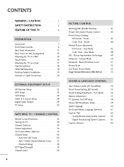
... HD Receiver Setup 21 DVD Setup 24 VCR Setup 26 Other A/V Source Setup 28 Digital Audio Output 28 PC Setup 29 WATCHING TV / CHANNEL CONTROL Remote Control Functions 32 Turning On TV 34 Channel Selection 34 Volume Adjustment 34 On-Screen Menus Selection 35 Channel Setup 36 - Auto Scan (EZ Scan 36 - Black...
... HD Receiver Setup 21 DVD Setup 24 VCR Setup 26 Other A/V Source Setup 28 Digital Audio Output 28 PC Setup 29 WATCHING TV / CHANNEL CONTROL Remote Control Functions 32 Turning On TV 34 Channel Selection 34 Volume Adjustment 34 On-Screen Menus Selection 35 Channel Setup 36 - Auto Scan (EZ Scan 36 - Black...

Owners Manual
Page 7
... & General 78 TV Rating English & French 79 APPENDIX Troubleshooting 80 Maintenance 82 Product Specifications 83 Programming the Remote Control 84 Set ID 86 IR Codes 87 5 TIME SETTING ... Rating (MPAA) 77 Downloadable Rating 77 - Setting up Your Password 74 Set Password 75 Lock System 75 Channel Blocking 76 External Input Blocking 76 Movie & TV Rating 77 -
... & General 78 TV Rating English & French 79 APPENDIX Troubleshooting 80 Maintenance 82 Product Specifications 83 Programming the Remote Control 84 Set ID 86 IR Codes 87 5 TIME SETTING ... Rating (MPAA) 77 Downloadable Rating 77 - Setting up Your Password 74 Set Password 75 Lock System 75 Channel Blocking 76 External Input Blocking 76 Movie & TV Rating 77 -

Owners Manual
Page 8
...variety of time. Thus a few cell defects are operating and cooling the Plasma TV. The noise from the cooling fans is acceptable and is nothing wrong with general household waste. Avoid touching the LCD screen or holding your plasma display in Cathode Ray Tube (CRT) devices such ...inches thick. 160° - The fan noise doesn't have no adverse effect on the Plasma TV's efficiency or reliability. FOR LCD TV If the TV feels cold to viewers anywhere in other Plasma TV manufacturers' products. However, they have any negative effect on the monitor's performance. The fluorescent ...
...variety of time. Thus a few cell defects are operating and cooling the Plasma TV. The noise from the cooling fans is acceptable and is nothing wrong with general household waste. Avoid touching the LCD screen or holding your plasma display in Cathode Ray Tube (CRT) devices such ...inches thick. 160° - The fan noise doesn't have no adverse effect on the Plasma TV's efficiency or reliability. FOR LCD TV If the TV feels cold to viewers anywhere in other Plasma TV manufacturers' products. However, they have any negative effect on the monitor's performance. The fluorescent ...

Owners Manual
Page 9
... (Refer to p.13) 1-Bolt for fixing the 4-Bolts for stand Cable Holder assembly (Refer to p.13) (Refer to p.18) 32/37LC5DC*, 32/37LC50C* models only M4xL22 Torx plus Star head screw (Refer to maintain standard compliance for the product exteri- This feature is stain or ...Cloth * Do not wipe roughly when removing stain. PREPARATION PREPARATION ACCESSORIES Ensure that excessive pressure for all models. LCD TV PLASMA TV Owner's Manual http://www.lgusa.com www.lg.ca Copyright© 2007 LGE, All Rights Reserved. User must use shielded signal interface cables (D-sub 15 pin...
... (Refer to p.13) 1-Bolt for fixing the 4-Bolts for stand Cable Holder assembly (Refer to p.13) (Refer to p.18) 32/37LC5DC*, 32/37LC50C* models only M4xL22 Torx plus Star head screw (Refer to maintain standard compliance for the product exteri- This feature is stain or ...Cloth * Do not wipe roughly when removing stain. PREPARATION PREPARATION ACCESSORIES Ensure that excessive pressure for all models. LCD TV PLASMA TV Owner's Manual http://www.lgusa.com www.lg.ca Copyright© 2007 LGE, All Rights Reserved. User must use shielded signal interface cables (D-sub 15 pin...
Owners Manual
Page 10
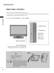
...product with a cloth (If a polishing cloth is included with your product has a protection tape attached, remove the tape. ed as parts of the TV). or Tighten the two of these four screws and x 2 x 2 the two Torx plus star head screws with the four screws (provided as ...bit (not provided as parts of the TV) to secure the TV. Illuminates green when the TV is in standby mode. PREPARATION FRONT PANEL CONTROLS ■ Here shown may be somewhat different from your TV. ■ If your product, use it). 32/37/42LC5DC*,32/37/42LC50C*, 42LB5DC, 42LB50C PREPARATION Remote Control...
...product with a cloth (If a polishing cloth is included with your product has a protection tape attached, remove the tape. ed as parts of the TV). or Tighten the two of these four screws and x 2 x 2 the two Torx plus star head screws with the four screws (provided as ...bit (not provided as parts of the TV) to secure the TV. Illuminates green when the TV is in standby mode. PREPARATION FRONT PANEL CONTROLS ■ Here shown may be somewhat different from your TV. ■ If your product, use it). 32/37/42LC5DC*,32/37/42LC50C*, 42LB5DC, 42LB50C PREPARATION Remote Control...

Owners Manual
Page 11
CH VOL ENTER MENU INPUT ON/OFF ON/OFF Button INPUT Button MENU Button ENTER Button VOLUME Buttons CHANNEL Buttons 9 Illuminates green when the TV is in standby mode. PREPARATION 32LX5DC*, 32LX50C* Remote Control Sensor Power/Standby Indicator Illuminates red when the TV is switched on.
CH VOL ENTER MENU INPUT ON/OFF ON/OFF Button INPUT Button MENU Button ENTER Button VOLUME Buttons CHANNEL Buttons 9 Illuminates green when the TV is in standby mode. PREPARATION 32LX5DC*, 32LX50C* Remote Control Sensor Power/Standby Indicator Illuminates red when the TV is switched on.
Owners Manual
Page 12
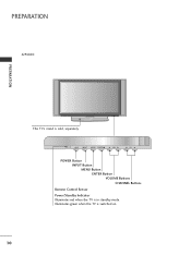
INPUT MENU ENTER VOL CH POWER Button INPUT Button MENU Button ENTER Button VOLUME Buttons CHANNEL Buttons Remote Control Sensor Power/Standby Indicator Illuminates red when the TV is sold, separately. PREPARATION 42PX8DC PREPARATION INPUT ENTER This TV's stand is in standby mode. Illuminates green when the TV is switched on. 10 INPUT ENTER
INPUT MENU ENTER VOL CH POWER Button INPUT Button MENU Button ENTER Button VOLUME Buttons CHANNEL Buttons Remote Control Sensor Power/Standby Indicator Illuminates red when the TV is sold, separately. PREPARATION 42PX8DC PREPARATION INPUT ENTER This TV's stand is in standby mode. Illuminates green when the TV is switched on. 10 INPUT ENTER

Owners Manual
Page 13
PREPARATION BACK PANEL INFORMATION ■ Here shown may be somewhat different from your TV. 32/37/42LC5DC*,32/37/42LC50C*, 42LB5DC, 42LB50C S-VIDEO S-VIDEO Input Provides better picture quality than the video input. AUDIO Input 11 11 VIDEO Input Connects the video signal ...
PREPARATION BACK PANEL INFORMATION ■ Here shown may be somewhat different from your TV. 32/37/42LC5DC*,32/37/42LC50C*, 42LB5DC, 42LB50C S-VIDEO S-VIDEO Input Provides better picture quality than the video input. AUDIO Input 11 11 VIDEO Input Connects the video signal ...

Owners Manual
Page 14
...REMOTE CONTROL OUT 5 SERVICE ONLY 6 RGB IN (PC) Connect the output from a PC. Caution: Never attempt to operate the TV on DC power. 12 ANTENNA IN Connect over-the air signals to either input. 2 DIGITAL AUDIO OUT Connect digital audio from an ...audio from a PC or DTV. 7 SPEAKER OUT 8Ω 8 AV (Audio/Video) IN 1 Connect audio/video output from your TV. PREPARATION PREPARATION ■ Here shown may be somewhat different from an external device to these ports do not work. 3 13 M.P.I... a HDMI (DVI) connection to this jack. 12 This part mainly use picture for the LCD TV models.
...REMOTE CONTROL OUT 5 SERVICE ONLY 6 RGB IN (PC) Connect the output from a PC. Caution: Never attempt to operate the TV on DC power. 12 ANTENNA IN Connect over-the air signals to either input. 2 DIGITAL AUDIO OUT Connect digital audio from an ...audio from a PC or DTV. 7 SPEAKER OUT 8Ω 8 AV (Audio/Video) IN 1 Connect audio/video output from your TV. PREPARATION PREPARATION ■ Here shown may be somewhat different from an external device to these ports do not work. 3 13 M.P.I... a HDMI (DVI) connection to this jack. 12 This part mainly use picture for the LCD TV models.

Owners Manual
Page 15
... HOLDER as shown. 2 Install the CABLE MANAGEMENT as necessary. PREPARATION BACK COVER FOR WIRE ARRANGEMENT ■ Here shown may be somewhat different from your TV. 32/37/42LC5DC*,32/37/42LC50C*, 42LB5DC, 42LB50C 1 Connect the cables as shown. BOLT CABLE HOLDER 3 Bundle the cables using the supplied twister holder. (This feature is dropped...
... HOLDER as shown. 2 Install the CABLE MANAGEMENT as necessary. PREPARATION BACK COVER FOR WIRE ARRANGEMENT ■ Here shown may be somewhat different from your TV. 32/37/42LC5DC*,32/37/42LC50C*, 42LB5DC, 42LB50C 1 Connect the cables as shown. BOLT CABLE HOLDER 3 Bundle the cables using the supplied twister holder. (This feature is dropped...

Owners Manual
Page 16
PREPARATION 2 Connect the cables as shown. 4 Bundle the cables using the supplied twister holder. (This feature is not available for all models.) 14 BOLT CABLE HOLDER TWISTER HOLDER To connect an additional equipment, see the EXTERNAL EQUIPMENT SETUP section. 3 Install the CABLE HOLDER as necessary. PREPARATION BACK COVER FOR WIRE ARRANGEMENT ■ Here shown may be somewhat different from your TV. 32LX5DC*, 32LX50C* 1 To separate the CABLE HOLDER, loosen the bolt installed the set.
PREPARATION 2 Connect the cables as shown. 4 Bundle the cables using the supplied twister holder. (This feature is not available for all models.) 14 BOLT CABLE HOLDER TWISTER HOLDER To connect an additional equipment, see the EXTERNAL EQUIPMENT SETUP section. 3 Install the CABLE HOLDER as necessary. PREPARATION BACK COVER FOR WIRE ARRANGEMENT ■ Here shown may be somewhat different from your TV. 32LX5DC*, 32LX50C* 1 To separate the CABLE HOLDER, loosen the bolt installed the set.
Owners Manual
Page 18
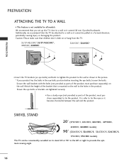
... sturdy rope (not provided as parts of the bracket that children don't climb on or hang from the TV. 32/37/42LC5DC*,32/37/42LC50C*, 42LB5DC, 42LB50C 32LX5DC*, 32LX50C* PREPARATION ■ Insert the TV brackets (or eye-bolts) and bolts to tighten the product to tie the rope so it cannot fall over... between the wall and the product. SWIVEL STAND 20° (37LC5DC1, 42LC5DC, 42LC50C, 42PX8DC, 42LB5DC, 42LB50C models) 90° (32LX5DC/S, 32LX50C/S, 32LC5DC/S, 32LC50C/S, 37LC5DC, 37LC50C models) The TV can be pulled in the product. Additionally, we recommend that you set up the...
... sturdy rope (not provided as parts of the bracket that children don't climb on or hang from the TV. 32/37/42LC5DC*,32/37/42LC50C*, 42LB5DC, 42LB50C 32LX5DC*, 32LX50C* PREPARATION ■ Insert the TV brackets (or eye-bolts) and bolts to tighten the product to tie the rope so it cannot fall over... between the wall and the product. SWIVEL STAND 20° (37LC5DC1, 42LC5DC, 42LC50C, 42PX8DC, 42LB5DC, 42LB50C models) 90° (32LX5DC/S, 32LX50C/S, 32LC5DC/S, 32LC50C/S, 37LC5DC, 37LC50C models) The TV can be pulled in the product. Additionally, we recommend that you set up the...

Owners Manual
Page 19
M5 x 25 32/37/42LC5DC*, 32/37/42LC50C*, 42LB5DC, 42LB50C 32LX5DC*, 32LX50C* 4-Screws Stand Desk 42PX8DC 4-Screws Stand Desk Stand 2-Screws Desk WARNING G This apparatus must be attached to desk so it cannot be securely attached to the floor/wall per installation instructions.Tipping, shaking, or rocking the machine may cause injury/death. 17 PREPARATION ATTACHING THE TV TO A DESK The TV must be pulled in a forward/backward direction, potentially causing injury or damaging the product. * Screws - M5 x L (table depth + 8~10 mm) ex) table depth-15mm: Bolts -
M5 x 25 32/37/42LC5DC*, 32/37/42LC50C*, 42LB5DC, 42LB50C 32LX5DC*, 32LX50C* 4-Screws Stand Desk 42PX8DC 4-Screws Stand Desk Stand 2-Screws Desk WARNING G This apparatus must be attached to desk so it cannot be securely attached to the floor/wall per installation instructions.Tipping, shaking, or rocking the machine may cause injury/death. 17 PREPARATION ATTACHING THE TV TO A DESK The TV must be pulled in a forward/backward direction, potentially causing injury or damaging the product. * Screws - M5 x L (table depth + 8~10 mm) ex) table depth-15mm: Bolts -

Owners Manual
Page 22
... in a poor signal area, please purchase a signal amplifier and install properly. ■ If the antenna needs to be split for two TV's, install a 2-Way Signal Splitter. ■ If the antenna is not installed properly, contact your dealer for outdoor antenna) Copper Wire Be... cable, and digital channel scans are complete. 20 Antenna (Analog or Digital) Wall Antenna Socket or Outdoor Antenna without a Cable Box Connections. Cable Cable TV Wall Jack RF Coaxial Wire (75 ohm) Single-family Dwellings /Houses (Connect to wall antenna socket) ANTENNA IN M.P.I . ANTENNA IN M.P.I . Outdoor ...
... in a poor signal area, please purchase a signal amplifier and install properly. ■ If the antenna needs to be split for two TV's, install a 2-Way Signal Splitter. ■ If the antenna is not installed properly, contact your dealer for outdoor antenna) Copper Wire Be... cable, and digital channel scans are complete. 20 Antenna (Analog or Digital) Wall Antenna Socket or Outdoor Antenna without a Cable Box Connections. Cable Cable TV Wall Jack RF Coaxial Wire (75 ohm) Single-family Dwellings /Houses (Connect to wall antenna socket) ANTENNA IN M.P.I . ANTENNA IN M.P.I . Outdoor ...

Owners Manual
Page 23
...shown below. When connecting Component cable 1. Match the jack colors (Y = green, PB = blue, and PR = red). HD RECEIVER SETUP This TV can receive Digital Over-the-air/Cable signals without an external digital set . EXTERNAL EQUIPMENT SETUP EXTERNAL EQUIPMENT SETUP ■ To prevent the equipment damage... set-top box.) ■ Select Component input source with using the INPUT button on the remote control. How to the owner's manual for LCD TV models. RJP RFACE VIDEO AUDIO S-VIDEO ( ) COMPONENT IN Signal 480i 480p 720p 1080i 1080p Component Yes Yes Yes Yes Yes * 42LB5DC, ...
...shown below. When connecting Component cable 1. Match the jack colors (Y = green, PB = blue, and PR = red). HD RECEIVER SETUP This TV can receive Digital Over-the-air/Cable signals without an external digital set . EXTERNAL EQUIPMENT SETUP EXTERNAL EQUIPMENT SETUP ■ To prevent the equipment damage... set-top box.) ■ Select Component input source with using the INPUT button on the remote control. How to the owner's manual for LCD TV models. RJP RFACE VIDEO AUDIO S-VIDEO ( ) COMPONENT IN Signal 480i 480p 720p 1080i 1080p Component Yes Yes Yes Yes Yes * 42LB5DC, ...

Owners Manual
Page 26
Y PB PR L R Connect the audio outputs of the DVD to the COMPONENT IN VIDEO jacks on the set . 2. Component ports on the TV Y Y Video output ports Y on the remote control. ■ Refer to the 2 COMPONENT IN AUDIO jacks on the DVD player, insert a DVD. RJP ERFACE VIDEO AUDIO S-...
Y PB PR L R Connect the audio outputs of the DVD to the COMPONENT IN VIDEO jacks on the set . 2. Component ports on the TV Y Y Video output ports Y on the remote control. ■ Refer to the 2 COMPONENT IN AUDIO jacks on the DVD player, insert a DVD. RJP ERFACE VIDEO AUDIO S-...

Owners Manual
Page 28
... is common to all manufactures and in socket of the VCR. 2. This phenomenon is used; the fixed images on the sides of time. (Only Plasma TV model). When connecting with an antenna 1 S-VIDEO VIDEO L R ANT OUT OUTPUT SWITCH ANT IN Wall Jack 2 Antenna ANTENNA IN M.P.I. 1. How to ...the screen. EXTERNAL EQUIPMENT SETUP EXTERNAL EQUIPMENT SETUP VCR SETUP ■ To avoid picture noise (interference), leave an adequate distance between the VCR and TV. ■ Use the ISM feature in the Option menu to avoid having a fixed image remain on the set. 2 Connect the antenna cable...
... is common to all manufactures and in socket of the VCR. 2. This phenomenon is used; the fixed images on the sides of time. (Only Plasma TV model). When connecting with an antenna 1 S-VIDEO VIDEO L R ANT OUT OUTPUT SWITCH ANT IN Wall Jack 2 Antenna ANTENNA IN M.P.I. 1. How to ...the screen. EXTERNAL EQUIPMENT SETUP EXTERNAL EQUIPMENT SETUP VCR SETUP ■ To avoid picture noise (interference), leave an adequate distance between the VCR and TV. ■ Use the ISM feature in the Option menu to avoid having a fixed image remain on the set. 2 Connect the antenna cable...

Owners Manual
Page 29
... the same time. NOTE G The picture quality is improved: compared to AV IN2, select A V 2 input source. How to connect 1 Connect the AUDIO/VIDEO jacks between TV and VCR. How to connect M.P.I .
... the same time. NOTE G The picture quality is improved: compared to AV IN2, select A V 2 input source. How to connect 1 Connect the AUDIO/VIDEO jacks between TV and VCR. How to connect M.P.I .


