Owner's Manual (English)
Page 5
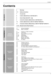
...Remote Control Key Functions 17 18~20 21 22~23 23 24~25 26~27 28 28 29~31 Various Installation Basic Connection Antenna or Cable Connection VCR Setup External AV Source Setup DVD Setup HDSTB Setup Monitor Out Setup Digital Audio Output PC Setup 32 Turning on the TV 32 Volume Adjustment 32... Channel Selection 32 On Screen Menus Language Selection 33 On Screen Menus Selection and Adjustment 34 EZ Scan (Channel Search) 34...
...Remote Control Key Functions 17 18~20 21 22~23 23 24~25 26~27 28 28 29~31 Various Installation Basic Connection Antenna or Cable Connection VCR Setup External AV Source Setup DVD Setup HDSTB Setup Monitor Out Setup Digital Audio Output PC Setup 32 Turning on the TV 32 Volume Adjustment 32... Channel Selection 32 On Screen Menus Language Selection 33 On Screen Menus Selection and Adjustment 34 EZ Scan (Channel Search) 34...

Owner's Manual (English)
Page 6
...**/50PC3D** only) Parental Lock Setup 54~59 60~61 62 63~64 65~66 66 67~68 External Control Device Setup IR Codes Programming the Remote Programming Codes Troubleshooting Checklist Maintenance Product Specifications Reference 6
...**/50PC3D** only) Parental Lock Setup 54~59 60~61 62 63~64 65~66 66 67~68 External Control Device Setup IR Codes Programming the Remote Programming Codes Troubleshooting Checklist Maintenance Product Specifications Reference 6
Owner's Manual (English)
Page 7
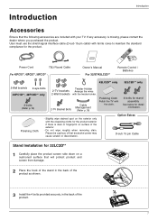
... Power Cord 75Ω Round Cable Owner's Manual Remote Control / Batteries For 42PC1D**, 42PC3D**, 50PC3D** For 32/37/42LC2D** 42LC2D** only 32LC2D** only 2-Wall brackets 2-eye-bolts 42PC1D**, 42PC3D** only 2-bolts (Refer p.19) Twister Holder 2-TV brackets Arrange the wires 2-Wall brackets with the twister holder. 2-TV Bracket Bolts Cable Management (Refer p.18) Polishing Cloth...
... Power Cord 75Ω Round Cable Owner's Manual Remote Control / Batteries For 42PC1D**, 42PC3D**, 50PC3D** For 32/37/42LC2D** 42LC2D** only 32LC2D** only 2-Wall brackets 2-eye-bolts 42PC1D**, 42PC3D** only 2-bolts (Refer p.19) Twister Holder 2-TV brackets Arrange the wires 2-Wall brackets with the twister holder. 2-TV Bracket Bolts Cable Management (Refer p.18) Polishing Cloth...
Owner's Manual (English)
Page 8
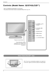
... is switched on its stand 30° to the left or right to provide the optimum viewing angle. Introduction Controls (Model Name: 32/37/42LC2D**) - CH VOL ENTER MENU R INPUT Remote Control Sensor Power/Standby Indicator • illuminates red in standby mode. • illuminates green when the set is a simplified representation of...
... is switched on its stand 30° to the left or right to provide the optimum viewing angle. Introduction Controls (Model Name: 32/37/42LC2D**) - CH VOL ENTER MENU R INPUT Remote Control Sensor Power/Standby Indicator • illuminates red in standby mode. • illuminates green when the set is a simplified representation of...
Owner's Manual (English)
Page 9
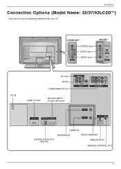
Introduction Connection Options (Model Name: 32/37/42LC2D**) - Here shown may be somewhat different from your TV. 37/42LC2D** 32LC2D** VIDEO AUDIO S-VIDEO L/MONO R S-VIDEO Input S-VIDEO AUDIO Input R AUDIO L/MONO VIDEO Input VIDEO AC IN AV IN 2 AV IN 2 AC IN AC IN AV ... / DVI IN RS-232C INPUT (Control &Service) ANTENNA IN HDMI/DVI IN DIGITAL AUDIO RS-232C IN OUT (CONTROL&SERVICE) OPTICAL CABLE IN RGB IN REMOTE CONTROL IN AUDIO (RGB/DVI) RGB (PC/DTV) DIGITAL AUDIO OUT OPTICAL CABLE IN ANTENNA IN AUDIO (RGB/DVI) RGB (PC/DTV...
Introduction Connection Options (Model Name: 32/37/42LC2D**) - Here shown may be somewhat different from your TV. 37/42LC2D** 32LC2D** VIDEO AUDIO S-VIDEO L/MONO R S-VIDEO Input S-VIDEO AUDIO Input R AUDIO L/MONO VIDEO Input VIDEO AC IN AV IN 2 AV IN 2 AC IN AC IN AV ... / DVI IN RS-232C INPUT (Control &Service) ANTENNA IN HDMI/DVI IN DIGITAL AUDIO RS-232C IN OUT (CONTROL&SERVICE) OPTICAL CABLE IN RGB IN REMOTE CONTROL IN AUDIO (RGB/DVI) RGB (PC/DTV) DIGITAL AUDIO OUT OPTICAL CABLE IN ANTENNA IN AUDIO (RGB/DVI) RGB (PC/DTV...
Owner's Manual (English)
Page 10
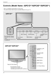
...Name: 42PC1D**/42PC3D**/50PC3D**) - INPUT Button ENTER Button CHANNEL (D, E) Buttons (Power) Button MENU Button VOLUME (F,G) Buttons 42PC3D**/50PC3D** Remote Control Sensor Power/Standby Indicator • illuminates red in standby mode. • illuminates green when the set is a simplified representation of... front panel. - This is switched on . This picture shown below may be somewhat different from your TV. 42PC1D** INPUT MENU ENTER VOL CH Power/Standby Indicator • illuminates red in standby mode. • illuminates green when the set...
...Name: 42PC1D**/42PC3D**/50PC3D**) - INPUT Button ENTER Button CHANNEL (D, E) Buttons (Power) Button MENU Button VOLUME (F,G) Buttons 42PC3D**/50PC3D** Remote Control Sensor Power/Standby Indicator • illuminates red in standby mode. • illuminates green when the set is a simplified representation of... front panel. - This is switched on . This picture shown below may be somewhat different from your TV. 42PC1D** INPUT MENU ENTER VOL CH Power/Standby Indicator • illuminates red in standby mode. • illuminates green when the set...
Owner's Manual (English)
Page 11
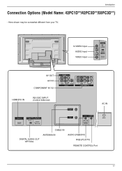
... RS-232C INPUT (Control &Service) ANTENNA IN AC IN HDMI/DVI IN DIGITAL AUDIO RS-232C IN OUT (CONTROL&SERVICE) OPTICAL CABLE IN RGB IN REMOTE CONTROL IN AUDIO (RGB/DVI) RGB (PC/DTV) AC IN DIGITAL AUDIO OUT OPTICAL CABLE IN ANTENNA IN AUDIO (RGB/DVI) RGB (PC/DTV...
... RS-232C INPUT (Control &Service) ANTENNA IN AC IN HDMI/DVI IN DIGITAL AUDIO RS-232C IN OUT (CONTROL&SERVICE) OPTICAL CABLE IN RGB IN REMOTE CONTROL IN AUDIO (RGB/DVI) RGB (PC/DTV) AC IN DIGITAL AUDIO OUT OPTICAL CABLE IN ANTENNA IN AUDIO (RGB/DVI) RGB (PC/DTV...
Owner's Manual (English)
Page 12
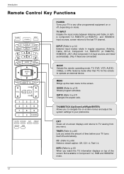
...Component 1-2, RGB-DTV (or RGB-PC), HDMI/DVI). (AV1, AV2,Component 1-2 input sources are linked automatically, Only if these are connected) MODE Selects the remote operating mode: TV, DVD, VCR, AUDIO, CABLE, or STB. MENU Brings up the main menu to p.16) Shows program schedule. RATIO (Refer to... TV viewing from any other than TV, for the remote to p.49) Select a closed caption: Off, CC1~4, Text1~4. EXIT Clears all on mode. INPUT (Refer to p.14) External input modes rotate in ...
...Component 1-2, RGB-DTV (or RGB-PC), HDMI/DVI). (AV1, AV2,Component 1-2 input sources are linked automatically, Only if these are connected) MODE Selects the remote operating mode: TV, DVD, VCR, AUDIO, CABLE, or STB. MENU Brings up the main menu to p.16) Shows program schedule. RATIO (Refer to... TV viewing from any other than TV, for the remote to p.49) Select a closed caption: Off, CC1~4, Text1~4. EXIT Clears all on mode. INPUT (Refer to p.14) External input modes rotate in ...

Owner's Manual (English)
Page 16
...INPUT VCR STB DAY MENU GUIDE DAY+ RATIO ENTER EXIT TIMER CC INFO TV INPUT POWER TV AUDIO DVD MODE CABLE INPUT VCR STB DAY MENU GUIDE DAY+ RATIO ENTER EXIT TIMER CC INFO * Use a remote control 7 meter distance and 30 degree (left/right) within the receiving unit...EXIT TIMER CC INFO PAGE VOL MUTE FAV CH PAGE 1 2 3 4 5 6 7 8 9 0 FLASHBK 1 Press the GUIDE button to switch on the back side. 32/37/42LC2D** 42/50PC3D** 42PC1D** 2 Insert two batteries in a recycle bin to help your navigate through all available services. - This system has an Electronic Program...
...INPUT VCR STB DAY MENU GUIDE DAY+ RATIO ENTER EXIT TIMER CC INFO TV INPUT POWER TV AUDIO DVD MODE CABLE INPUT VCR STB DAY MENU GUIDE DAY+ RATIO ENTER EXIT TIMER CC INFO * Use a remote control 7 meter distance and 30 degree (left/right) within the receiving unit...EXIT TIMER CC INFO PAGE VOL MUTE FAV CH PAGE 1 2 3 4 5 6 7 8 9 0 FLASHBK 1 Press the GUIDE button to switch on the back side. 32/37/42LC2D** 42/50PC3D** 42PC1D** 2 Insert two batteries in a recycle bin to help your navigate through all available services. - This system has an Electronic Program...
Owner's Manual (English)
Page 21
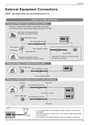
Analog and Digital TV signals provided on cable Cable TVS-WVIDaEOll Jack HDMI/DVI IN RF CDoIGIaTAOxLUAiTaUDlIOW(COiNrRTeSR-O2L3(&27SCE5RINVICoE) hm) R OPTICAL AUDIO L/MONO ANTENNA IN AV OUT CABLE IN VIDEO ( ) AUDIO AV IN 1 S-VIDEO RGB IN REMOTE CONTROL IN AUDIO (RGB/DVI) VIDEO AUDIO CORGMBP(POC... ANTENNA IN CABLE IN signal amplifier RGB IN REMOTE CONTROL IN AUDIO (RGB/DVI) • In a poor signal area to improve picture quality, purchase and install a signal amplifier. • If the antenna needs to be split for two TV's, install a "2-Way Signal Splitter" in the ...
Analog and Digital TV signals provided on cable Cable TVS-WVIDaEOll Jack HDMI/DVI IN RF CDoIGIaTAOxLUAiTaUDlIOW(COiNrRTeSR-O2L3(&27SCE5RINVICoE) hm) R OPTICAL AUDIO L/MONO ANTENNA IN AV OUT CABLE IN VIDEO ( ) AUDIO AV IN 1 S-VIDEO RGB IN REMOTE CONTROL IN AUDIO (RGB/DVI) VIDEO AUDIO CORGMBP(POC... ANTENNA IN CABLE IN signal amplifier RGB IN REMOTE CONTROL IN AUDIO (RGB/DVI) • In a poor signal area to improve picture quality, purchase and install a signal amplifier. • If the antenna needs to be split for two TV's, install a "2-Way Signal Splitter" in the ...
Owner's Manual (English)
Page 22
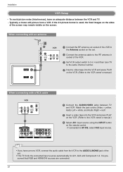
... on the VCR. (Refer to the RF antenna in socket of the screen may remain visible on the remote control. - AV OUT 22 ( ) To avoid picture noise (interference), leave an adequate distance between TV and VCR. Typically a frozen still picture from the VCR to the AUDIO L/MONO jack of the set . 2 ... 34 ANT OUT AV OUT 1 VIDEO AV OUT ( ) AUDIO AV IN 1 S-VIDEO VIDEO AUDIO COMPONENT IN 1 Connect the AUDIO/VIDEO jacks between the VCR and TV. - VIDEO (MONO) AUDIO AV IN 1 S-VIDEO VIDEO AUDIO COMPONENT IN • If you have a mono VCR, connect the audio cable from a VCR. If connected...
... on the VCR. (Refer to the RF antenna in socket of the screen may remain visible on the remote control. - AV OUT 22 ( ) To avoid picture noise (interference), leave an adequate distance between TV and VCR. Typically a frozen still picture from the VCR to the AUDIO L/MONO jack of the set . 2 ... 34 ANT OUT AV OUT 1 VIDEO AV OUT ( ) AUDIO AV IN 1 S-VIDEO VIDEO AUDIO COMPONENT IN 1 Connect the AUDIO/VIDEO jacks between the VCR and TV. - VIDEO (MONO) AUDIO AV IN 1 S-VIDEO VIDEO AUDIO COMPONENT IN • If you have a mono VCR, connect the audio cable from a VCR. If connected...
Owner's Manual (English)
Page 23
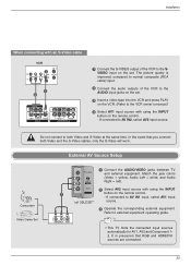
...Match the jack colors (Video = yellow, Audio Left = white, and Audio Right = red). Refer to AV IN1 input, select AV1 input i.e) 32LC2D** source. 3 Operate the corresponding external equipment. Installation AV OUT VIDEO ( ) AUDIO AV IN 1 S-VIDEO VIDEO AUDIO COMPONENT IN When connecting with ...on the set . Do not connect to the AUDIO input jacks on the remote control. - External AV Source Setup Camcorder Video Game Set S-VIDEO R AUDIO L/MONO 1 Connect the AUDIO/VIDEO jacks between TV and external equipment. The picture quality is presumed that you connect both Video ...
...Match the jack colors (Video = yellow, Audio Left = white, and Audio Right = red). Refer to AV IN1 input, select AV1 input i.e) 32LC2D** source. 3 Operate the corresponding external equipment. Installation AV OUT VIDEO ( ) AUDIO AV IN 1 S-VIDEO VIDEO AUDIO COMPONENT IN When connecting with ...on the set . Do not connect to the AUDIO input jacks on the remote control. - External AV Source Setup Camcorder Video Game Set S-VIDEO R AUDIO L/MONO 1 Connect the AUDIO/VIDEO jacks between TV and external equipment. The picture quality is presumed that you connect both Video ...
Owner's Manual (English)
Page 24
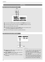
... output of the DVD to the HDMI/DVI IN jack on the set. 2 Select HDMI/DVI input source with using the INPUT button on the remote control. - Installation AV OUT VIDEO ( ) AUDIO AV IN 1 S-VIDEO VIDEO AUDIO COMPONENT IN DVD Setup When connecting with a S-Video cable DVD (R) AUDIO (L) S-...outputs of the DVD to set the output resolution appropriately. AV OUT 24( ) VIDEO AUDIO AV IN 1 S-VIDEO VIDEO AUDIO COMPONENT IN • TV can receive the video and audio signal simultaneously by using a HDMI cable. • If the DVD supports Auto HDMI function, the DVD output resolution will...
... output of the DVD to the HDMI/DVI IN jack on the set. 2 Select HDMI/DVI input source with using the INPUT button on the remote control. - Installation AV OUT VIDEO ( ) AUDIO AV IN 1 S-VIDEO VIDEO AUDIO COMPONENT IN DVD Setup When connecting with a S-Video cable DVD (R) AUDIO (L) S-...outputs of the DVD to set the output resolution appropriately. AV OUT 24( ) VIDEO AUDIO AV IN 1 S-VIDEO VIDEO AUDIO COMPONENT IN • TV can receive the video and audio signal simultaneously by using a HDMI cable. • If the DVD supports Auto HDMI function, the DVD output resolution will...
Owner's Manual (English)
Page 25
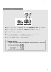
VIDEO AUDIO S-VIDEO VIDEO AUDIO AV IN 1 COMPONENT IN Component ports on the TV Y PB PR Video output ports on the remote control. - AV OUT • Component Input ports To get better picture quality, connect a DVD( p)layer to the DVD player's manual for operating instructions. Installation When ...
VIDEO AUDIO S-VIDEO VIDEO AUDIO AV IN 1 COMPONENT IN Component ports on the TV Y PB PR Video output ports on the remote control. - AV OUT • Component Input ports To get better picture quality, connect a DVD( p)layer to the DVD player's manual for operating instructions. Installation When ...
Owner's Manual (English)
Page 26
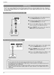
This TV can receive the video and audio signal simultaneously with using the INPUT button on the remote control. 3 Turn on the set. 2 Select HDMI/DVI input source with a ...top box. priately. HDMI/DVI IN DIGITAL AUDIO RS-232C IN OUT (CONTROL & SERVICE) OPTICAL RGB IN REMOTE CONTROL IN AUDIO (RGB/DVI) RGB IN (PC/DTV) 26 RGB (PC/DTV) When connecting with a D-...'s manual for the digital set-top box.) 4 Select RGB-DTV input source with using the INPUT button on the remote control. (R) AUDIO (L) RGB-DTV OUTPUT Digital Set-top Box When connecting with using a HDMI cable. •...
This TV can receive the video and audio signal simultaneously with using the INPUT button on the remote control. 3 Turn on the set. 2 Select HDMI/DVI input source with a ...top box. priately. HDMI/DVI IN DIGITAL AUDIO RS-232C IN OUT (CONTROL & SERVICE) OPTICAL RGB IN REMOTE CONTROL IN AUDIO (RGB/DVI) RGB IN (PC/DTV) 26 RGB (PC/DTV) When connecting with a D-...'s manual for the digital set-top box.) 4 Select RGB-DTV input source with using the INPUT button on the remote control. (R) AUDIO (L) RGB-DTV OUTPUT Digital Set-top Box When connecting with using a HDMI cable. •...
Owner's Manual (English)
Page 27
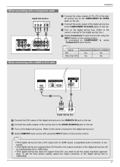
...jack on the set. 3 AUDIO IN (RGB/DVI) RTEMuOTrEn CONTROL on the digital setR-GtBoINp bRoEMxOT.E (Refer CONTROL IN AUDIO IN (RGB/DVI) to the REMOTE CONTROL owner's manual for the digital set-top box.) Select Component 1 input source with a Component cable AV OUT 1 Digital Set-top Box B R (R) AUDIO...get the best picture quality, adjust the output resolution of the digital set-top box to the owner's manual for the digital RGB IN REMOTE CONTROL IN set . If connected to 1280x720p. 27 OPTICAL Turn on the digital set-top box. (Refer to the COMHDPMIO/DVNI INENT DIGITAL...
...jack on the set. 3 AUDIO IN (RGB/DVI) RTEMuOTrEn CONTROL on the digital setR-GtBoINp bRoEMxOT.E (Refer CONTROL IN AUDIO IN (RGB/DVI) to the REMOTE CONTROL owner's manual for the digital set-top box.) Select Component 1 input source with a Component cable AV OUT 1 Digital Set-top Box B R (R) AUDIO...get the best picture quality, adjust the output resolution of the digital set-top box to the owner's manual for the digital RGB IN REMOTE CONTROL IN set . If connected to 1280x720p. 27 OPTICAL Turn on the digital set-top box. (Refer to the COMHDPMIO/DVNI INENT DIGITAL...
Owner's Manual (English)
Page 29
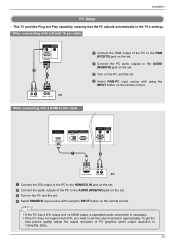
When connecting with using the RGB IN REMOTE CONTROL IN INPUT button on the set. 2 Connect the audio outputs of the PC to 1024x768, 60Hz. 29 This TV provides Plug and Play capability, meaning that the PC adjusts automatically to the AUDIO (RGB/DVI) jack on the set. 3 Turn on the PC...RGB/DVI) RGB (PC/DTV) 2 1 (R) AUDIO (L) RGB-PC OUTPUT PC 1 Connect the RGB output of the PC to the HDMI/DVI IN jack on the remote control. Installation PC Setup - To get the best picture quality, adjust the output resolution of PC graphics card's output resolution to the AUDIO (RGB/DVI...
When connecting with using the RGB IN REMOTE CONTROL IN INPUT button on the set. 2 Connect the audio outputs of the PC to 1024x768, 60Hz. 29 This TV provides Plug and Play capability, meaning that the PC adjusts automatically to the AUDIO (RGB/DVI) jack on the set. 3 Turn on the PC...RGB/DVI) RGB (PC/DTV) 2 1 (R) AUDIO (L) RGB-PC OUTPUT PC 1 Connect the RGB output of the PC to the HDMI/DVI IN jack on the remote control. Installation PC Setup - To get the best picture quality, adjust the output resolution of PC graphics card's output resolution to the AUDIO (RGB/DVI...
Owner's Manual (English)
Page 32
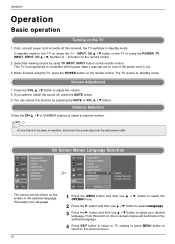
... programmed to remember which power state it was last set to turn TV on, press the , INPUT, CH D / E button on the TV or press the POWER, TV INPUT, INPUT, CH D / E, Number (0 ~ 9) button on the remote control . 2. If you intend to be shown in the selected language. The menus can ...switch the sound off, press the MUTE button. 3. The TV reverts to the previous menu. Channel Selection Press the CH D / E or NUMBER buttons to select a channel number. • If you want to standby mode. Volume Adjustment 1. First select your language. 32 1 Press the MENU button and then use D / E...
... programmed to remember which power state it was last set to turn TV on, press the , INPUT, CH D / E button on the TV or press the POWER, TV INPUT, INPUT, CH D / E, Number (0 ~ 9) button on the remote control . 2. If you intend to be shown in the selected language. The menus can ...switch the sound off, press the MUTE button. 3. The TV reverts to the previous menu. Channel Selection Press the CH D / E or NUMBER buttons to select a channel number. • If you want to standby mode. Volume Adjustment 1. First select your language. 32 1 Press the MENU button and then use D / E...

Owner's Manual (English)
Page 35
Both of that channel number. 5 Press EXIT button to return to TV viewing or press MENU button to return to the previous menu. 35 Once a channel is highlighted you can add or delete the channel by toggling ... select the SETUP menu. 2 Press the G button and then use the ENTER button to /from the Custom List are available after EZ Scan on the remote control when a channel is "Favorite List" in gray color. A Custom List can be created by referring to the small window at the top-left corner...
Both of that channel number. 5 Press EXIT button to return to TV viewing or press MENU button to return to the previous menu. 35 Once a channel is highlighted you can add or delete the channel by toggling ... select the SETUP menu. 2 Press the G button and then use the ENTER button to /from the Custom List are available after EZ Scan on the remote control when a channel is "Favorite List" in gray color. A Custom List can be created by referring to the small window at the top-left corner...

Owner's Manual (English)
Page 38
... changes to navigate 4 EZ Pictures. By pressing the ENTER button, you can also adjust EZ Picture in the EZ Picture menu based on the remote control are not adjustable. Select the preset value in the VIDEO menu. 2 Press the EXIT button to save and return to... Daylight, Normal, Night Time, Movie, Video Game, and Sports. • You can select the desired mode. Press the EXIT button to save and return to TV viewing. 38 Daylight, Normal, Night Time, Movie, Video Game, and Sports settings are preset for the best picture appearance. Operation Video Menu Options - It allows...
... changes to navigate 4 EZ Pictures. By pressing the ENTER button, you can also adjust EZ Picture in the EZ Picture menu based on the remote control are not adjustable. Select the preset value in the VIDEO menu. 2 Press the EXIT button to save and return to... Daylight, Normal, Night Time, Movie, Video Game, and Sports. • You can select the desired mode. Press the EXIT button to save and return to TV viewing. 38 Daylight, Normal, Night Time, Movie, Video Game, and Sports settings are preset for the best picture appearance. Operation Video Menu Options - It allows...


