
FS-C5016N Operation Guide
Page 24
... cap which is used to seal the box opening when being disposed of. 5 Main Charger Units The main charger units are electrical components included in each toner container and are used to clean the corresponding main charger unit. 1-6 1.2 Parts and Functions 1.2.2 Left 3 1 5 2 4 Figure 1-2 1 Face-...down Tray This tray receives printouts face down. 2 Power Switch This switch turns printer power on and off. 3 Left Cover This cover needs to be sure to transfer toner onto the drum unit.
... cap which is used to seal the box opening when being disposed of. 5 Main Charger Units The main charger units are electrical components included in each toner container and are used to clean the corresponding main charger unit. 1-6 1.2 Parts and Functions 1.2.2 Left 3 1 5 2 4 Figure 1-2 1 Face-...down Tray This tray receives printouts face down. 2 Power Switch This switch turns printer power on and off. 3 Left Cover This cover needs to be sure to transfer toner onto the drum unit.

Service Manual
Page 9
...Parts names ...1-1-3 (1) Overall ...1-1-3 (2) Operation panel ...1-1-4 1-1-3 Cross section view ...1-1-5 1-2 Handling Precautions 1-2-1 Drum unit ...1-2-1 1-2-2 Installation environment ...1-2-1 1-3 Installation 1-3-1 Unpacking and installation ...1-3-1 (1) Installation procedure ...1-3-1 1-3-2 Installing expansion memory (optional 1-3-7 1-3-3 Installing a memory card (optional) ...1-3-8 1-3-4 Installing network interface card (optional 1-3-9 1-3-5 Installing hard disk unit (optional) ...1-3-10 1-4 Service Mode 1-4-1 Service mode ...1-4-1 (1) Executing service mode ...1-4-1 1-4-2 Maintenance...
...Parts names ...1-1-3 (1) Overall ...1-1-3 (2) Operation panel ...1-1-4 1-1-3 Cross section view ...1-1-5 1-2 Handling Precautions 1-2-1 Drum unit ...1-2-1 1-2-2 Installation environment ...1-2-1 1-3 Installation 1-3-1 Unpacking and installation ...1-3-1 (1) Installation procedure ...1-3-1 1-3-2 Installing expansion memory (optional 1-3-7 1-3-3 Installing a memory card (optional) ...1-3-8 1-3-4 Installing network interface card (optional 1-3-9 1-3-5 Installing hard disk unit (optional) ...1-3-10 1-4 Service Mode 1-4-1 Service mode ...1-4-1 (1) Executing service mode ...1-4-1 1-4-2 Maintenance...

Service Manual
Page 10
... from paper cassette 2-1-1 (2) Paper feeding from MP tray ...2-1-5 2-1-2 Developing section ...2-1-7 (1) Developer unit ...2-1-7 (2) Touch down developing method ...2-1-9 2-1-3 Drum section ...2-1-10 (1) Drum unit ...2-1-10 (2) Waste toner ejecting mechanism 2-1-13 (3) LED print head ...2-1-14 (4) Main charger unit ...2-1-16 2-1-4 Primary transfer section ...2-1-18 (1) Primary transfer unit ...2-1-18 (2) Primary transfer cleaning unit ...2-1-20 2-1-5 Secondary transfer and separation section 2-1-23 2-1-6 Fuser section ...2-1-25 (1) Fuser...
... from paper cassette 2-1-1 (2) Paper feeding from MP tray ...2-1-5 2-1-2 Developing section ...2-1-7 (1) Developer unit ...2-1-7 (2) Touch down developing method ...2-1-9 2-1-3 Drum section ...2-1-10 (1) Drum unit ...2-1-10 (2) Waste toner ejecting mechanism 2-1-13 (3) LED print head ...2-1-14 (4) Main charger unit ...2-1-16 2-1-4 Primary transfer section ...2-1-18 (1) Primary transfer unit ...2-1-18 (2) Primary transfer cleaning unit ...2-1-20 2-1-5 Secondary transfer and separation section 2-1-23 2-1-6 Fuser section ...2-1-25 (1) Fuser...

Service Manual
Page 17
... tray unit (vertical path) 21. 1-1-3 Cross section view ) * $ @8 4 !7 3 06 2 9 5 1 # FS-C5016N % ^ & ⁄ ( Optional Duplexer Optional Paper feeders Paper path (Main unit) Paper path (Optional unit) 1. Black developer unit 6. Primary transfer cleaning unit 15. Magenta drum unit 5. Yellow toner container 11. Paper cassette 1-1-5 Black drum unit 2. MP tray 16. Magenta toner container 13. Fuser unit 19. Cyan developer unit 8. Cyan drum unit 4. Magenta developer unit 9. Primary transfer unit...
... tray unit (vertical path) 21. 1-1-3 Cross section view ) * $ @8 4 !7 3 06 2 9 5 1 # FS-C5016N % ^ & ⁄ ( Optional Duplexer Optional Paper feeders Paper path (Main unit) Paper path (Optional unit) 1. Black developer unit 6. Primary transfer cleaning unit 15. Magenta drum unit 5. Yellow toner container 11. Paper cassette 1-1-5 Black drum unit 2. MP tray 16. Magenta toner container 13. Fuser unit 19. Cyan developer unit 8. Cyan drum unit 4. Magenta developer unit 9. Primary transfer unit...

Service Manual
Page 19
...be touched by hands or stained with oil, clean it. Ensure that may affect the quality of the machine. Developer unit and toner container Store the toner container in temperature and humidity. • Avoid exposure to any substance which is ...Hz ±2% 5. Humidity: 20 - 80%RH 3. Avoid direct light and high humidity. 1-2-2 Installation environment 1. FS-C5016N 1-2-1 Drum unit Note the following when handling or storing the drum unit. • When removing the drum unit, never expose the drum surface to strong direct light. • Avoid abrupt changes in a cool, dark place.
...be touched by hands or stained with oil, clean it. Ensure that may affect the quality of the machine. Developer unit and toner container Store the toner container in temperature and humidity. • Avoid exposure to any substance which is ...Hz ±2% 5. Humidity: 20 - 80%RH 3. Avoid direct light and high humidity. 1-2-2 Installation environment 1. FS-C5016N 1-2-1 Drum unit Note the following when handling or storing the drum unit. • When removing the drum unit, never expose the drum surface to strong direct light. • Avoid abrupt changes in a cool, dark place.

Service Manual
Page 34
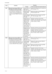
FS-C5016N Service items Description Items 5 Total page 6 Parallel I/O information 7 Serial I/O error code 8 Operation panel lock status (displayed only when locked) 9 NVRAM error (displayed ...Cassette 5/Duplexer /Paper feeder 1/Paper feeder 2 /Paper feeder 3 / Duplexer/ /Cyan drum unit/Magenta drum unit/Yellow drum unit/ Black drum unit /Cyan/Magenta/Yellow/Black /Paper feeder1/Paper feeder 2/Paper feeder 3/Envelope feeder/Duplexer /Cyan/Magenta/Yellow/Black 0: Normal bit0 to 3: LED print head compensation data in the LED print head memory PWB (0: Black, 1: Yellow, 2: Cyan, 3: Magenta) bit4: ...
FS-C5016N Service items Description Items 5 Total page 6 Parallel I/O information 7 Serial I/O error code 8 Operation panel lock status (displayed only when locked) 9 NVRAM error (displayed ...Cassette 5/Duplexer /Paper feeder 1/Paper feeder 2 /Paper feeder 3 / Duplexer/ /Cyan drum unit/Magenta drum unit/Yellow drum unit/ Black drum unit /Cyan/Magenta/Yellow/Black /Paper feeder1/Paper feeder 2/Paper feeder 3/Envelope feeder/Duplexer /Cyan/Magenta/Yellow/Black 0: Normal bit0 to 3: LED print head compensation data in the LED print head memory PWB (0: Black, 1: Yellow, 2: Cyan, 3: Magenta) bit4: ...

Service Manual
Page 41
... readability, resulting in green. *2: Each portion of colors has three different magnitude of halftones (bands). Start Enter the service mode [>>Printing Test Page]. It also results in vertical streaks in uneven density. Completion FS-C5016N Density*2 16/256 24/256 32/256 black Black... 32/256 bands. Purpose To check the activation of the developer and drum units of four colors. The test page is printed. Service items >>Print Test Page Printing a test page Description Description Four colors are not recognizable with halftones of three different levels. Figure 1-4-5 Test page...
... readability, resulting in green. *2: Each portion of colors has three different magnitude of halftones (bands). Start Enter the service mode [>>Printing Test Page]. It also results in vertical streaks in uneven density. Completion FS-C5016N Density*2 16/256 24/256 32/256 black Black... 32/256 bands. Purpose To check the activation of the developer and drum units of four colors. The test page is printed. Service items >>Print Test Page Printing a test page Description Description Four colors are not recognizable with halftones of three different levels. Figure 1-4-5 Test page...
Service Manual
Page 42
...drum units (See page 1-6-12). 2. Remove the LED print head from each component is displayed. is reset immediately. Install the four new drum units. 4. Replace the retard roller (See page 1-6-7). 11. Press the ENTER key, ">>Maintenance ?" Replace the two ozone filters (See page 1-6-35). 10. Procedure for the developer units and drum units...for each old drum unit and then refit to determine the possibility that maintenance kit should be manually reset using this service item. Start Enter the service mode [>>Maintenance]. FS-C5016N Service items >>...
...drum units (See page 1-6-12). 2. Remove the LED print head from each component is displayed. is reset immediately. Install the four new drum units. 4. Replace the retard roller (See page 1-6-7). 11. Press the ENTER key, ">>Maintenance ?" Replace the two ozone filters (See page 1-6-35). 10. Procedure for the developer units and drum units...for each old drum unit and then refit to determine the possibility that maintenance kit should be manually reset using this service item. Start Enter the service mode [>>Maintenance]. FS-C5016N Service items >>...

Service Manual
Page 43
... cleaning blade in the drum unit scrapes toner off the drum surface to contamination. Procedure 1. Press the ENTER key. Enter the service mode [>>Drum]. 2. Press the ENTER key. Drum surface refreshing will be displayed. 3. will start and finish after approximately 3 minutes. 1-4-13 FS-C5016N Service items >>Drum Drum surface refreshing Description Description Rotates the drum approximately 5 minutes with toner...
... cleaning blade in the drum unit scrapes toner off the drum surface to contamination. Procedure 1. Press the ENTER key. Enter the service mode [>>Drum]. 2. Press the ENTER key. Drum surface refreshing will be displayed. 3. will start and finish after approximately 3 minutes. 1-4-13 FS-C5016N Service items >>Drum Drum surface refreshing Description Description Rotates the drum approximately 5 minutes with toner...
Service Manual
Page 48
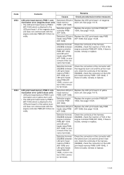
.... See page 1-6-28. FS-C5016N Code 0951 0952 Contents Causes Remarks Check procedures/corrective measures LED print head memory PWB 4 communication error (black drum unit) • The LED print head memory PWB 4 (KP-1040) which is attached to the LED print head 4 of the Black drum unit does not communicate with the cyan drum unit and the printer main unit, check the continuity...
.... See page 1-6-28. FS-C5016N Code 0951 0952 Contents Causes Remarks Check procedures/corrective measures LED print head memory PWB 4 communication error (black drum unit) • The LED print head memory PWB 4 (KP-1040) which is attached to the LED print head 4 of the Black drum unit does not communicate with the cyan drum unit and the printer main unit, check the continuity...
Service Manual
Page 49
...the engine controller PWB (KP1054). Check the connection of the connector with the magenta drum unit and the printer main unit, check the continuity of the harness (S02866), check the connection of the LED print head memory PWB 1 (KP-1040), if there is trouble, remedy or ... 1-6-28. FS-C5016N Code 0953 0954 Contents Causes Remarks Check procedures/corrective measures LED print head memory PWB 1 communication error (magenta drum unit) • The LED print head memory PWB 2 (KP-1040) which is attached to the LED print head 1 of the magenta drum unit does not communicate...
...the engine controller PWB (KP1054). Check the connection of the connector with the magenta drum unit and the printer main unit, check the continuity of the harness (S02866), check the connection of the LED print head memory PWB 1 (KP-1040), if there is trouble, remedy or ... 1-6-28. FS-C5016N Code 0953 0954 Contents Causes Remarks Check procedures/corrective measures LED print head memory PWB 1 communication error (magenta drum unit) • The LED print head memory PWB 2 (KP-1040) which is attached to the LED print head 1 of the magenta drum unit does not communicate...

Service Manual
Page 50
... engine controller PWB (KP-1054). Refer to the duplexer DU-300's service manual. See page 1-6-28. (KP-1048). 1-5-6 FS-C5016N Code 1200 2610 2620 2630 5301 Contents Causes Remarks Check procedures/corrective measures Side registration motor error • The duplexer PWB of the...Replace the eraser lamp 4 [PWB] (KP-976). Replace the engine controller PWB (KP1054). Defective drum Replace the black drum unit. See page 1-6- Defective harness between engine controller PWB (KP-1054) and LED print heads relay PWB (KP-1048), or poor contact of the optional paper feeder (top). ...
... engine controller PWB (KP-1054). Refer to the duplexer DU-300's service manual. See page 1-6-28. (KP-1048). 1-5-6 FS-C5016N Code 1200 2610 2620 2630 5301 Contents Causes Remarks Check procedures/corrective measures Side registration motor error • The duplexer PWB of the...Replace the eraser lamp 4 [PWB] (KP-976). Replace the engine controller PWB (KP1054). Defective drum Replace the black drum unit. See page 1-6- Defective harness between engine controller PWB (KP-1054) and LED print heads relay PWB (KP-1048), or poor contact of the optional paper feeder (top). ...

Service Manual
Page 51
...poor contact of the connector terminals. Replace the eraser lamp 1 [PWB] (KP-976). Defective drum Replace the magenta drum unit. Defective harness between engine controller PWB (KP-1054) and LED print heads relay PWB (KP-1048), or poor contact of the connector terminals. Defective harness ... replace. Defective drum Replace the cyan drum unit. Eraser lamp 1 error (magenta drum unit) • The eraser lamp 1 [PWB] (KP-976) of the cyan drum unit does not communicate with the engine controller PWB (KP-1054) normally. See page 1-6-28. (KP-1048). 1-5-7 FS-C5016N Code 5302 5303...
...poor contact of the connector terminals. Replace the eraser lamp 1 [PWB] (KP-976). Defective drum Replace the magenta drum unit. Defective harness between engine controller PWB (KP-1054) and LED print heads relay PWB (KP-1048), or poor contact of the connector terminals. Defective harness ... replace. Defective drum Replace the cyan drum unit. Eraser lamp 1 error (magenta drum unit) • The eraser lamp 1 [PWB] (KP-976) of the cyan drum unit does not communicate with the engine controller PWB (KP-1054) normally. See page 1-6-28. (KP-1048). 1-5-7 FS-C5016N Code 5302 5303...

Service Manual
Page 52
... controller PWB (KP-1054). FS-C5016N Code 5304 Contents Causes Remarks Check procedures/corrective measures Eraser lamp 3 error (yellow drum unit) Defective eraser • The eraser lamp 3 [PWB] (KP-976) of the connector terminals. See page 1-6-25. Defective drum Replace the yellow drum unit. Defective harness between engine controller PWB (KP-1054) and LED print heads relay PWB...
... controller PWB (KP-1054). FS-C5016N Code 5304 Contents Causes Remarks Check procedures/corrective measures Eraser lamp 3 error (yellow drum unit) Defective eraser • The eraser lamp 3 [PWB] (KP-976) of the connector terminals. See page 1-6-25. Defective drum Replace the yellow drum unit. Defective harness between engine controller PWB (KP-1054) and LED print heads relay PWB...

Service Manual
Page 59
...drum unit and the printer main unit, check the continuity of the engine controller PWB (KP1054), if there is trouble, remedy or replace. PWB 2 (KP-972). Replace the engine controller PWB (KP1054). Defective LED print Replace the LED print heads relay PWB heads relay PWB (KP-1048). See page 1-6-25. FS-C5016N... Code 7411 7412 Contents Causes Remarks Check procedures/corrective measures Black drum unit non- PWB 4 (...
...drum unit and the printer main unit, check the continuity of the engine controller PWB (KP1054), if there is trouble, remedy or replace. PWB 2 (KP-972). Replace the engine controller PWB (KP1054). Defective LED print Replace the LED print heads relay PWB heads relay PWB (KP-1048). See page 1-6-25. FS-C5016N... Code 7411 7412 Contents Causes Remarks Check procedures/corrective measures Black drum unit non- PWB 4 (...

Service Manual
Page 60
... replace. 1-5-16 FS-C5016N Code 7413 7414 Contents Causes Remarks Check procedures/corrective measures Magenta drum unit non- Defective drum Replace the drum PWB 1 (KP-972). Yellow drum unit non- Defective drum Replace the drum PWB 3 (KP-972). See page 1-6-25. Defective harness (S02869) between drum PWB 3 (KP-972) and printer main unit or poor contact of the connector terminals. Defective LED print Replace...
... replace. 1-5-16 FS-C5016N Code 7413 7414 Contents Causes Remarks Check procedures/corrective measures Magenta drum unit non- Defective drum Replace the drum PWB 1 (KP-972). Yellow drum unit non- Defective drum Replace the drum PWB 3 (KP-972). See page 1-6-25. Defective harness (S02869) between drum PWB 3 (KP-972) and printer main unit or poor contact of the connector terminals. Defective LED print Replace...

Service Manual
Page 66
Malfunction of main high voltage PWB. The LED print head has not done functioning. Loose connection with drum connectors. Defective main controller PWB. See page 1-6-24. Replace the LED print heads relay PWB (KP-1048). B. Replace the main high voltage PWB (KP-978). See...LED print heads relay PWB. Defective engine controller PWB. 2. Check connection between the drum unit and the unit frame. Replace the main controller PWB (KP-957). The LED print head has not done functioning. 2. Causes Check procedures/corrective measures 1. A. No main charging. 2. See page 1-6-29. FS-C5016N...
Malfunction of main high voltage PWB. The LED print head has not done functioning. Loose connection with drum connectors. Defective main controller PWB. See page 1-6-24. Replace the LED print heads relay PWB (KP-1048). B. Replace the main high voltage PWB (KP-978). See...LED print heads relay PWB. Defective engine controller PWB. 2. Check connection between the drum unit and the unit frame. Replace the main controller PWB (KP-957). The LED print head has not done functioning. 2. Causes Check procedures/corrective measures 1. A. No main charging. 2. See page 1-6-29. FS-C5016N...
Service Manual
Page 68
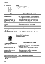
FS-C5016N (5) Image is colored. Replace the main controller PWB (KP-957). Perform the drum surface refreshing. See page 1-4-12. 3. B. The printer environment considerably changed since an automatic calibration was made . 4. Perform the color calibration of service mode. Causes 1. Defective developing sleeve bias output. 2. Defective color calibration. Defective developing sleeve bias output. Defective bias high voltage PWB. C. A. If...
FS-C5016N (5) Image is colored. Replace the main controller PWB (KP-957). Perform the drum surface refreshing. See page 1-4-12. 3. B. The printer environment considerably changed since an automatic calibration was made . 4. Perform the color calibration of service mode. Causes 1. Defective developing sleeve bias output. 2. Defective color calibration. Defective developing sleeve bias output. Defective bias high voltage PWB. C. A. If...

Service Manual
Page 69
... charger wire by using main charger wire cleaner. If the white line appears on a particular color, replace the LED print head for that color. Deformed or worn cleaning blade in the drum unit. 5. FS-C5016N Causes 1. Clean the SELFOC lens of LED print head by using the test print of image by using main charger wire cleaner. Replace...
... charger wire by using main charger wire cleaner. If the white line appears on a particular color, replace the LED print head for that color. Deformed or worn cleaning blade in the drum unit. 5. FS-C5016N Causes 1. Clean the SELFOC lens of LED print head by using the test print of image by using main charger wire cleaner. Replace...

Service Manual
Page 70
... press roller cleaning. Replace the developer. Poor contact of grounding terminal of main charger unit. 2. Check procedures/corrective measures Insert the main charger properly. Replace the primary transfer cleaning unit. FS-C5016N (9) Streaks are printed. Poor contact of output terminal of drum unit. 3. Causes 1. See page 1-6-12. See page 1-6-11. (10) Spots are printed horizontally. See...
... press roller cleaning. Replace the developer. Poor contact of grounding terminal of main charger unit. 2. Check procedures/corrective measures Insert the main charger properly. Replace the primary transfer cleaning unit. FS-C5016N (9) Streaks are printed. Poor contact of output terminal of drum unit. 3. Causes 1. See page 1-6-12. See page 1-6-11. (10) Spots are printed horizontally. See...


