Service Manual
Page 11
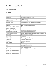
... of output trays (80 g/m2 [0.11 mm thickness]) Specification Electrophotography laser scan 14 pages/min. (A4) 15 pages/min. (Letter) Fast 1200 mode (1800 horizontal/600 vertical) 600 horizontal/600 vertical KIR (Kyocera Image Refinement) 22 seconds or less 10 seconds or less (from sleep...reached first Mono component developer Visible laser Scorotron positive charging Negative charger roller Curvature separation Blade Eraser lamp (LED array) Heat roller and press roller Plain paper: Legal to A5 Cassette: 250 sheets, MP tray: 50 sheets Face-up: 30 sheets, Face-down: 150 sheets FS-1050 1-3
... of output trays (80 g/m2 [0.11 mm thickness]) Specification Electrophotography laser scan 14 pages/min. (A4) 15 pages/min. (Letter) Fast 1200 mode (1800 horizontal/600 vertical) 600 horizontal/600 vertical KIR (Kyocera Image Refinement) 22 seconds or less 10 seconds or less (from sleep...reached first Mono component developer Visible laser Scorotron positive charging Negative charger roller Curvature separation Blade Eraser lamp (LED array) Heat roller and press roller Plain paper: Legal to A5 Cassette: 250 sheets, MP tray: 50 sheets Face-up: 30 sheets, Face-down: 150 sheets FS-1050 1-3

Service Manual
Page 12
protrusions) Width: Height: Depth: Weight: 378 mm (147/8 inches) 244 mm (83/4 inches) 375 mm (143/4 inches) 9.8 Kg (2015/16 lb.) FS-1050 1-4 (2) Controller Item Specification CPU PowerPC405/200MHz System ROM 4 MB Flash DIMM Font ROM 2 MB (16 M bit × 1) Optional font ROM (Dip socket) 1 MB (Optional ...115.2 Kbps (Optional serial interface board) KUIO-LV (3.3 V) Page description language Prescribe 2e Standard emulation modes PCL6, Diablo 630, IBM proprinter X24E, Epson LQ850, Line printer, KPDL2 (3) Weight and dimensions Item Specification Item S Main unit (excl.
protrusions) Width: Height: Depth: Weight: 378 mm (147/8 inches) 244 mm (83/4 inches) 375 mm (143/4 inches) 9.8 Kg (2015/16 lb.) FS-1050 1-4 (2) Controller Item Specification CPU PowerPC405/200MHz System ROM 4 MB Flash DIMM Font ROM 2 MB (16 M bit × 1) Optional font ROM (Dip socket) 1 MB (Optional ...115.2 Kbps (Optional serial interface board) KUIO-LV (3.3 V) Page description language Prescribe 2e Standard emulation modes PCL6, Diablo 630, IBM proprinter X24E, Epson LQ850, Line printer, KPDL2 (3) Weight and dimensions Item Specification Item S Main unit (excl.

Service Manual
Page 13
(4) Power requirements Item Voltage/current requirement Watts Specification Item S 220 to 240 V AC ±10 %, 50/60 Hz ±2 %/3.8 A Normal operation: 265 W Maximum: 818 W Standby: 13 W Sleeping: 5 W (5) Environmental requirements Item Operating temperature and humidity Maximum altitude Noise emission (Excluding peaks, measured at 1 m from printer, as per ISO7779) Specification Item S 10 to 32.5 °C (50 to 90.5 °F), 20 to 80 %RH 2,000 m (6,500 feet) 50 dB (A) maximum/28 dB (A) at standby/unmeasureably low at sleeping) FS-1050 1-5
(4) Power requirements Item Voltage/current requirement Watts Specification Item S 220 to 240 V AC ±10 %, 50/60 Hz ±2 %/3.8 A Normal operation: 265 W Maximum: 818 W Standby: 13 W Sleeping: 5 W (5) Environmental requirements Item Operating temperature and humidity Maximum altitude Noise emission (Excluding peaks, measured at 1 m from printer, as per ISO7779) Specification Item S 10 to 32.5 °C (50 to 90.5 °F), 20 to 80 %RH 2,000 m (6,500 feet) 50 dB (A) maximum/28 dB (A) at standby/unmeasureably low at sleeping) FS-1050 1-5

Service Manual
Page 14
USB interface connector @ Power switch # AC inlet Figure 1-2-1 Name of parts 2 1 3 5 4 8 7 6 9 ! 0 @ # 1 Top cover 2 Face-down output tray 3 Face-up output tray 4 Side cover 5 Operator panel 6 Front cover 7 Paper cassette 8 MP tray 9 Option card slot 0 Parallel interface connector ! 1-2 Names of parts 1-2-1 Name of parts FS-1050 1-6
USB interface connector @ Power switch # AC inlet Figure 1-2-1 Name of parts 2 1 3 5 4 8 7 6 9 ! 0 @ # 1 Top cover 2 Face-down output tray 3 Face-up output tray 4 Side cover 5 Operator panel 6 Front cover 7 Paper cassette 8 MP tray 9 Option card slot 0 Parallel interface connector ! 1-2 Names of parts 1-2-1 Name of parts FS-1050 1-6
Service Manual
Page 15
... to the requirements of 1968. Observe these cautionary statements and figures when handling the laser scanner unit. This means that the printer does not produce hazardous laser radiation. FS-1050 1-7 to conform to the requirements of DHHS 21 CFR Subchapter for Class I laser product conforming to Radiation Control for Health and Safety Act of IEC 825...
... to the requirements of 1968. Observe these cautionary statements and figures when handling the laser scanner unit. This means that the printer does not produce hazardous laser radiation. FS-1050 1-7 to conform to the requirements of DHHS 21 CFR Subchapter for Class I laser product conforming to Radiation Control for Health and Safety Act of IEC 825...
Service Manual
Page 16
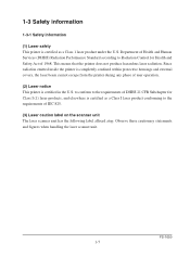
WARNING Use of controls or adjustments or performance of procedures other than those specified herein may result in hazardous radiation exposure. Label on the left cover rear side - Label on the scanner unit (Inside the printer) Label on the fuser unit Figure 1-3-1 Caution labels FS-1050 1-8
WARNING Use of controls or adjustments or performance of procedures other than those specified herein may result in hazardous radiation exposure. Label on the left cover rear side - Label on the scanner unit (Inside the printer) Label on the fuser unit Figure 1-3-1 Caution labels FS-1050 1-8
Service Manual
Page 17
... or disconnecting an interface cable to the printer. These regulations apply to install the printer in a confined area where ventilation is blocked. (6) Optional equipment The printer may concentrate in use capped using the protective cap supplied. FS-1050 1-9 A label indicating compliance with the CDRH regulations must be attached to laser products marketed in the United States...
... or disconnecting an interface cable to the printer. These regulations apply to install the printer in a confined area where ventilation is blocked. (6) Optional equipment The printer may concentrate in use capped using the protective cap supplied. FS-1050 1-9 A label indicating compliance with the CDRH regulations must be attached to laser products marketed in the United States...
Service Manual
Page 18
...and not too damp or dry (See section Environmental requirements on page 1-5). FS-1050 1-10 If you install the printer where the temperature or humidity is : • Level and well supported (Place the printer on a table or desk.) • Not exposed to sunlight or ... its service life. The use an extension cord, the total length of the printer. The printer will be an increased chance of paper jams. • Provide a sufficient clearances around the printer to an uncurtained window). 1-4 Environmental requirements 1-4-1 Environmental conditions The Environmental requirements section...
...and not too damp or dry (See section Environmental requirements on page 1-5). FS-1050 1-10 If you install the printer where the temperature or humidity is : • Level and well supported (Place the printer on a table or desk.) • Not exposed to sunlight or ... its service life. The use an extension cord, the total length of the printer. The printer will be an increased chance of paper jams. • Provide a sufficient clearances around the printer to an uncurtained window). 1-4 Environmental requirements 1-4-1 Environmental conditions The Environmental requirements section...

Service Manual
Page 19
(1) Clearance Allow the necessary minimum clearance on all sides of the printer as diagrammed below. 5 4 1 3 2 Figure 1-4-2 Clearances Ref. Clearance Dimensions 1 Left 25 cm (9-7/8 inches) 2 Front 50 cm (19-11/16 inches) 3 Right 25 cm (9-7/8 inches) 4 Back 40 cm (15-3/4 inches) 5 Above 30 cm (11-13/16 inches) 1-11 FS-1050
(1) Clearance Allow the necessary minimum clearance on all sides of the printer as diagrammed below. 5 4 1 3 2 Figure 1-4-2 Clearances Ref. Clearance Dimensions 1 Left 25 cm (9-7/8 inches) 2 Front 50 cm (19-11/16 inches) 3 Right 25 cm (9-7/8 inches) 4 Back 40 cm (15-3/4 inches) 5 Above 30 cm (11-13/16 inches) 1-11 FS-1050

Service Manual
Page 20
...power cord and any other electric parts which may cause contamination on power Use only the power source voltage conforming to the printer's rated power voltage. FS-1050 1-12 WARNING As the disconnect device is given to do so when performing tests described in this manual. • ...8226; Avoid enclosed spaces that block ventilation. • Avoid sites more than 6,500 feet or 2,000 meters above sea level. (3) Note on the laser scanner window, causing print quality problem. • Vibration. • Ammonia fumes or other electrical part. • An easily accessible socket outlet must...
...power cord and any other electric parts which may cause contamination on power Use only the power source voltage conforming to the printer's rated power voltage. FS-1050 1-12 WARNING As the disconnect device is given to do so when performing tests described in this manual. • ...8226; Avoid enclosed spaces that block ventilation. • Avoid sites more than 6,500 feet or 2,000 meters above sea level. (3) Note on the laser scanner window, causing print quality problem. • Vibration. • Ammonia fumes or other electrical part. • An easily accessible socket outlet must...

Service Manual
Page 21
... the following precautions in removal and transportation of the printer. • Be sure to repack the printer in its original carton. • Do not leave the printer, toner container, process unit and other printer modules inside when a vehicle is more than 25 °C. As unexpectedly ... may result in moisture condensation which will affect the performance of more than 7 °C within 30 minutes. • Before removing the printer to allow minimum air circulation or the adequate air conditioning should be parked in a vehicle, it . The vehicle during transportation should be ...
... the following precautions in removal and transportation of the printer. • Be sure to repack the printer in its original carton. • Do not leave the printer, toner container, process unit and other printer modules inside when a vehicle is more than 25 °C. As unexpectedly ... may result in moisture condensation which will affect the performance of more than 7 °C within 30 minutes. • Before removing the printer to allow minimum air circulation or the adequate air conditioning should be parked in a vehicle, it . The vehicle during transportation should be ...

Service Manual
Page 22
... 1-5-1 Toner container handling Do not attempt to disassemble or refill the toner container. FS-1050 1-14 This is because Kyocera have no means of control over how such refilled toner could affect the print quality and the reliability of the printer. (1) Toner container handling To loosen and mix the toner inside before use any...
... 1-5-1 Toner container handling Do not attempt to disassemble or refill the toner container. FS-1050 1-14 This is because Kyocera have no means of control over how such refilled toner could affect the print quality and the reliability of the printer. (1) Toner container handling To loosen and mix the toner inside before use any...

Service Manual
Page 23
... unit, put it in a protective bag and keep it with the toner container installed. Otherwise, toner may leak and contamination may result in the printer. 1-15 FS-1050 To ensure the high print quality, store the toner container in a place that satisfies the following environmental conditions: Temperature: -20 to 40 °C (-4 to 104...
... unit, put it in a protective bag and keep it with the toner container installed. Otherwise, toner may leak and contamination may result in the printer. 1-15 FS-1050 To ensure the high print quality, store the toner container in a place that satisfies the following environmental conditions: Temperature: -20 to 40 °C (-4 to 104...

Service Manual
Page 26
... all the accessories from the paper cassette. Toner container (TK-17) Cleaning cloth Printer Installation guide Kyocera Mita digital library CD-ROM Figure 2-1-1 Unpacking (1) Power cord Remove the tape on the rear side of the spacer and remove...2-1 Unpacking 2-1-1 Unpacking and inspection The package should contain the printer and the accessories as shown in the figure below. Tapes Spacer Printed notice Figure 2-1-2 Unpacking (2) 2-3 Spacer FS-1050 For unpacking, place the box containing the printer on top of the printer, and remove the two spacers and the printed notice from ...
... all the accessories from the paper cassette. Toner container (TK-17) Cleaning cloth Printer Installation guide Kyocera Mita digital library CD-ROM Figure 2-1-1 Unpacking (1) Power cord Remove the tape on the rear side of the spacer and remove...2-1 Unpacking 2-1-1 Unpacking and inspection The package should contain the printer and the accessories as shown in the figure below. Tapes Spacer Printed notice Figure 2-1-2 Unpacking (2) 2-3 Spacer FS-1050 For unpacking, place the box containing the printer on top of the printer, and remove the two spacers and the printed notice from ...

Service Manual
Page 27
If not, pull it forward until it is in the release (forward) position. Confirm that the lock lever #1 1 is used with the printer, begin installation with connecting the printer and the paper feeder. For details, refer to the optional Paper feeder's Service Manual. 2-2-1 Installing the toner container 1. Proceed as follows in sequence. Open the top cover all the way. 2. If the option paper feeder is in the release position. 1 Figure 2-2-1 Confirming the lock lever #1 FS-1050 2-4 2-2 Installing the printer Installing the printer requires several steps.
If not, pull it forward until it is in the release (forward) position. Confirm that the lock lever #1 1 is used with the printer, begin installation with connecting the printer and the paper feeder. For details, refer to the optional Paper feeder's Service Manual. 2-2-1 Installing the toner container 1. Proceed as follows in sequence. Open the top cover all the way. 2. If the option paper feeder is in the release position. 1 Figure 2-2-1 Confirming the lock lever #1 FS-1050 2-4 2-2 Installing the printer Installing the printer requires several steps.
Service Manual
Page 28
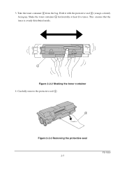
This ensures that the toner is evenly distributed inside. 2 Figure 2-2-2 Shaking the toner container 4. Hold it with the protective seal 3 (orange-colored) facing up. Shake the toner container 2 horizontally at least five times. Take the toner container 2 from the bag. 3. Carefully remove the protective seal 3. 3 Figure 2-2-3 Removing the protective seal 2-5 FS-1050
This ensures that the toner is evenly distributed inside. 2 Figure 2-2-2 Shaking the toner container 4. Hold it with the protective seal 3 (orange-colored) facing up. Shake the toner container 2 horizontally at least five times. Take the toner container 2 from the bag. 3. Carefully remove the protective seal 3. 3 Figure 2-2-3 Removing the protective seal 2-5 FS-1050
Service Manual
Page 29
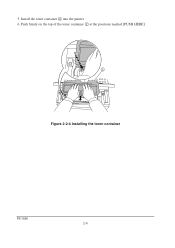
Push firmly on the top of the toner container 2 at the positions marked [PUSH HERE]. 2 Figure 2-2-4 Installing the toner container FS-1050 2-6 5. Install the toner container 2 into the printer. 6.
Push firmly on the top of the toner container 2 at the positions marked [PUSH HERE]. 2 Figure 2-2-4 Installing the toner container FS-1050 2-6 5. Install the toner container 2 into the printer. 6.

Service Manual
Page 30
... 4 LOCK UNLOCK LOCK UNLOCK NOTE Figure- 2-2-5 Locking the toner container The printer is first switched on after installing the new toner container, take the toner container...the toner container is approximately 15 minutes. This delay is necessary for the printer to fill the developer reservoir with no toner supplied in the manner above, there will be a...of several minutes before the printer gets ready to print a job. The period of toner to the lock position. 8. Push the lock lever #1 1 to continuously support a print job. When the printer is shipped from the factory ...
... 4 LOCK UNLOCK LOCK UNLOCK NOTE Figure- 2-2-5 Locking the toner container The printer is first switched on after installing the new toner container, take the toner container...the toner container is approximately 15 minutes. This delay is necessary for the printer to fill the developer reservoir with no toner supplied in the manner above, there will be a...of several minutes before the printer gets ready to print a job. The period of toner to the lock position. 8. Push the lock lever #1 1 to continuously support a print job. When the printer is shipped from the factory ...

Service Manual
Page 31
2-2-2 Expanding memory The FS-1050 printer comes standard equipped with resource protection Resolution 300 dpi 600 dpi 2 MB 2 MB - 10 MB (2) DIMM specifications Memory size in various environments. Printer memory can be expanded to up to the maximum 144 MB (16 + 128 MB). (1) Minimum memory requirements Refer to the table below for minimum memory ...) HP LaserJet 5P with 16 MB of pins Access speed Parity Bus width 16, 32, 64, 128 MB 100 pins 66 MHz None 32 bits FS-1050 2-8
2-2-2 Expanding memory The FS-1050 printer comes standard equipped with resource protection Resolution 300 dpi 600 dpi 2 MB 2 MB - 10 MB (2) DIMM specifications Memory size in various environments. Printer memory can be expanded to up to the maximum 144 MB (16 + 128 MB). (1) Minimum memory requirements Refer to the table below for minimum memory ...) HP LaserJet 5P with 16 MB of pins Access speed Parity Bus width 16, 32, 64, 128 MB 100 pins 66 MHz None 32 bits FS-1050 2-8

Service Manual
Page 32
Figure 2-2-6 Handling DIMM FS-1050 2-9 (3) Notes on handling DIMM Before proceeding to discharge yourself of static electricity. While doing the work, it is recommended that you wear an antistatic wrist strap. • Touch the main board and DIMM only by taking these precautions: • Before touching a DIMM, touch a water pipe or other large metal object to install DIMM, read the following notes for handling the main board and DIMMs: • Protect the electronics by the edges, not in the middle.
Figure 2-2-6 Handling DIMM FS-1050 2-9 (3) Notes on handling DIMM Before proceeding to discharge yourself of static electricity. While doing the work, it is recommended that you wear an antistatic wrist strap. • Touch the main board and DIMM only by taking these precautions: • Before touching a DIMM, touch a water pipe or other large metal object to install DIMM, read the following notes for handling the main board and DIMMs: • Protect the electronics by the edges, not in the middle.


