Service Manual
Page 11
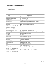
... of output trays (80 g/m2 [0.11 mm thickness]) Specification Electrophotography laser scan 14 pages/min. (A4) 15 pages/min. (Letter) Fast 1200 mode (1800 horizontal/600 vertical) 600 horizontal/600 vertical KIR (Kyocera Image Refinement) 22 seconds or less 10 seconds or less (from sleep...reached first Mono component developer Visible laser Scorotron positive charging Negative charger roller Curvature separation Blade Eraser lamp (LED array) Heat roller and press roller Plain paper: Legal to A5 Cassette: 250 sheets, MP tray: 50 sheets Face-up: 30 sheets, Face-down: 150 sheets FS-1050 1-3
... of output trays (80 g/m2 [0.11 mm thickness]) Specification Electrophotography laser scan 14 pages/min. (A4) 15 pages/min. (Letter) Fast 1200 mode (1800 horizontal/600 vertical) 600 horizontal/600 vertical KIR (Kyocera Image Refinement) 22 seconds or less 10 seconds or less (from sleep...reached first Mono component developer Visible laser Scorotron positive charging Negative charger roller Curvature separation Blade Eraser lamp (LED array) Heat roller and press roller Plain paper: Legal to A5 Cassette: 250 sheets, MP tray: 50 sheets Face-up: 30 sheets, Face-down: 150 sheets FS-1050 1-3

Service Manual
Page 12
...) 244 mm (83/4 inches) 375 mm (143/4 inches) 9.8 Kg (2015/16 lb.) FS-1050 1-4 speed: 115.2 Kbps (Optional serial interface board) KUIO-LV (3.3 V) Page description language Prescribe 2e Standard emulation modes PCL6, Diablo 630, IBM proprinter X24E, Epson LQ850, Line printer, KPDL2 (3) Weight and dimensions Item Specification Item S Main unit (excl. (2) Controller Item...
...) 244 mm (83/4 inches) 375 mm (143/4 inches) 9.8 Kg (2015/16 lb.) FS-1050 1-4 speed: 115.2 Kbps (Optional serial interface board) KUIO-LV (3.3 V) Page description language Prescribe 2e Standard emulation modes PCL6, Diablo 630, IBM proprinter X24E, Epson LQ850, Line printer, KPDL2 (3) Weight and dimensions Item Specification Item S Main unit (excl. (2) Controller Item...

Service Manual
Page 13
(4) Power requirements Item Voltage/current requirement Watts Specification Item S 220 to 240 V AC ±10 %, 50/60 Hz ±2 %/3.8 A Normal operation: 265 W Maximum: 818 W Standby: 13 W Sleeping: 5 W (5) Environmental requirements Item Operating temperature and humidity Maximum altitude Noise emission (Excluding peaks, measured at 1 m from printer, as per ISO7779) Specification Item S 10 to 32.5 °C (50 to 90.5 °F), 20 to 80 %RH 2,000 m (6,500 feet) 50 dB (A) maximum/28 dB (A) at standby/unmeasureably low at sleeping) FS-1050 1-5
(4) Power requirements Item Voltage/current requirement Watts Specification Item S 220 to 240 V AC ±10 %, 50/60 Hz ±2 %/3.8 A Normal operation: 265 W Maximum: 818 W Standby: 13 W Sleeping: 5 W (5) Environmental requirements Item Operating temperature and humidity Maximum altitude Noise emission (Excluding peaks, measured at 1 m from printer, as per ISO7779) Specification Item S 10 to 32.5 °C (50 to 90.5 °F), 20 to 80 %RH 2,000 m (6,500 feet) 50 dB (A) maximum/28 dB (A) at standby/unmeasureably low at sleeping) FS-1050 1-5
Service Manual
Page 15
... Act of user operation. (2) Laser notice This printer is certified as a Class 1 laser product under the U.S. Since radiation emitted inside the printer is completely confined within protective housings and external covers, the laser beam cannot escape from the printer during any phase of 1968. FS-1050 1-7 This means that the printer does not produce hazardous laser radiation. to conform to...
... Act of user operation. (2) Laser notice This printer is certified as a Class 1 laser product under the U.S. Since radiation emitted inside the printer is completely confined within protective housings and external covers, the laser beam cannot escape from the printer during any phase of 1968. FS-1050 1-7 This means that the printer does not produce hazardous laser radiation. to conform to...
Service Manual
Page 16
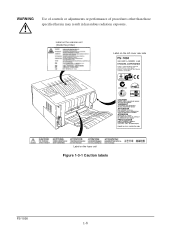
Label on the scanner unit (Inside the printer) Label on the fuser unit Figure 1-3-1 Caution labels FS-1050 1-8 Label on the left cover rear side - WARNING Use of controls or adjustments or performance of procedures other than those specified herein may result in hazardous radiation exposure.
Label on the scanner unit (Inside the printer) Label on the fuser unit Figure 1-3-1 Caution labels FS-1050 1-8 Label on the left cover rear side - WARNING Use of controls or adjustments or performance of procedures other than those specified herein may result in hazardous radiation exposure.
Service Manual
Page 17
... not in use capped using the protective cap supplied. FS-1050 1-9 (4) CDRH regulations (U.S.A.) The Center of Devices and Radiological Health (CDRH) of ozone gas to less than 0.1 ppm, we recommend you not to install the printer in a confined area where ventilation is mandatory for laser products on the interface connectors Be sure to turn...
... not in use capped using the protective cap supplied. FS-1050 1-9 (4) CDRH regulations (U.S.A.) The Center of Devices and Radiological Health (CDRH) of ozone gas to less than 0.1 ppm, we recommend you not to install the printer in a confined area where ventilation is mandatory for laser products on the interface connectors Be sure to turn...
Service Manual
Page 18
... it is outside the requirements in section Environmental requirements in chapter 1, the best print quality may result in a location that can be used for the printer alone. 1-4 Environmental requirements 1-4-1 Environmental conditions The Environmental requirements section on page 1-5 should be 17 feet or 5 meters or less. • Well ventilated, not too hot... or cold, and not too damp or dry (See section Environmental requirements on page 1-5). FS-1050 1-10 If you use of access. (See section Clearance on next page).
... it is outside the requirements in section Environmental requirements in chapter 1, the best print quality may result in a location that can be used for the printer alone. 1-4 Environmental requirements 1-4-1 Environmental conditions The Environmental requirements section on page 1-5 should be 17 feet or 5 meters or less. • Well ventilated, not too hot... or cold, and not too damp or dry (See section Environmental requirements on page 1-5). FS-1050 1-10 If you use of access. (See section Clearance on next page).

Service Manual
Page 19
(1) Clearance Allow the necessary minimum clearance on all sides of the printer as diagrammed below. 5 4 1 3 2 Figure 1-4-2 Clearances Ref. Clearance Dimensions 1 Left 25 cm (9-7/8 inches) 2 Front 50 cm (19-11/16 inches) 3 Right 25 cm (9-7/8 inches) 4 Back 40 cm (15-3/4 inches) 5 Above 30 cm (11-13/16 inches) 1-11 FS-1050
(1) Clearance Allow the necessary minimum clearance on all sides of the printer as diagrammed below. 5 4 1 3 2 Figure 1-4-2 Clearances Ref. Clearance Dimensions 1 Left 25 cm (9-7/8 inches) 2 Front 50 cm (19-11/16 inches) 3 Right 25 cm (9-7/8 inches) 4 Back 40 cm (15-3/4 inches) 5 Above 30 cm (11-13/16 inches) 1-11 FS-1050

Service Manual
Page 20
...power supply or any other electric parts which may cause contamination on the laser scanner window, causing print quality problem. • Vibration. • Ammonia fumes or other power sources. • Disconnect the printer from the power source before attempting removal or replacement of an electrical ..., an easily accessible socket outlet must be provided near the equipment. WARNING As the disconnect device is given to the printer's rated power voltage. FS-1050 1-12 Dust and smoke may give an electric shock. • Before performing maintenance or repair, power from both the...
...power supply or any other electric parts which may cause contamination on the laser scanner window, causing print quality problem. • Vibration. • Ammonia fumes or other power sources. • Disconnect the printer from the power source before attempting removal or replacement of an electrical ..., an easily accessible socket outlet must be provided near the equipment. WARNING As the disconnect device is given to the printer's rated power voltage. FS-1050 1-12 Dust and smoke may give an electric shock. • Before performing maintenance or repair, power from both the...

Service Manual
Page 21
... . Failure to a warm place, wrap it in a blanket, etc., before crating it may result in moisture condensation which will affect the performance of the printer. 1-13 FS-1050 The vehicle during transportation should be parked in the shade or with the window open to allow minimum air circulation or the adequate air conditioning...
... . Failure to a warm place, wrap it in a blanket, etc., before crating it may result in moisture condensation which will affect the performance of the printer. 1-13 FS-1050 The vehicle during transportation should be parked in the shade or with the window open to allow minimum air circulation or the adequate air conditioning...

Service Manual
Page 22
...quality and long service life, the following handling precautions should use , with Kyocera's proprietary toner, Kyocera do not recommend to disassemble or refill the toner container. FS-1050 1-14 This is because Kyocera have no means of control over how such refilled toner could affect the ...print quality and the reliability of the printer. (1) Toner container handling To loosen and mix...
...quality and long service life, the following handling precautions should use , with Kyocera's proprietary toner, Kyocera do not recommend to disassemble or refill the toner container. FS-1050 1-14 This is because Kyocera have no means of control over how such refilled toner could affect the ...print quality and the reliability of the printer. (1) Toner container handling To loosen and mix...

Service Manual
Page 23
... the toner container is shipped for return, etc., do not ship it in a dark place. Otherwise, toner may leak and contamination may result in the printer. 1-15 FS-1050 If the printer is removed from the printer's developer unit, put it in a protective bag and keep it with the toner container installed.
... the toner container is shipped for return, etc., do not ship it in a dark place. Otherwise, toner may leak and contamination may result in the printer. 1-15 FS-1050 If the printer is removed from the printer's developer unit, put it in a protective bag and keep it with the toner container installed.

Service Manual
Page 26
... printer, and remove the two spacers and the printed notice from the package. Carefully remove the printer. Remove the printer and all the accessories from the paper cassette. 2-1 Unpacking 2-1-1 Unpacking and inspection The package should contain the printer and the accessories as shown in the figure below. Tapes Spacer Printed notice Figure 2-1-2 Unpacking (2) 2-3 Spacer FS-1050...
... printer, and remove the two spacers and the printed notice from the package. Carefully remove the printer. Remove the printer and all the accessories from the paper cassette. 2-1 Unpacking 2-1-1 Unpacking and inspection The package should contain the printer and the accessories as shown in the figure below. Tapes Spacer Printed notice Figure 2-1-2 Unpacking (2) 2-3 Spacer FS-1050...

Service Manual
Page 27
Open the top cover all the way. 2. Proceed as follows in the release position. 1 Figure 2-2-1 Confirming the lock lever #1 FS-1050 2-4 If the option paper feeder is in the release (forward) position. If not, pull it forward until it is in sequence. For details, refer to the optional Paper feeder's Service Manual. 2-2-1 Installing the toner container 1. 2-2 Installing the printer Installing the printer requires several steps. Confirm that the lock lever #1 1 is used with the printer, begin installation with connecting the printer and the paper feeder.
Open the top cover all the way. 2. Proceed as follows in the release position. 1 Figure 2-2-1 Confirming the lock lever #1 FS-1050 2-4 If the option paper feeder is in the release (forward) position. If not, pull it forward until it is in sequence. For details, refer to the optional Paper feeder's Service Manual. 2-2-1 Installing the toner container 1. 2-2 Installing the printer Installing the printer requires several steps. Confirm that the lock lever #1 1 is used with the printer, begin installation with connecting the printer and the paper feeder.
Service Manual
Page 29
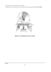
Install the toner container 2 into the printer. 6. 5. Push firmly on the top of the toner container 2 at the positions marked [PUSH HERE]. 2 Figure 2-2-4 Installing the toner container FS-1050 2-6
Install the toner container 2 into the printer. 6. 5. Push firmly on the top of the toner container 2 at the positions marked [PUSH HERE]. 2 Figure 2-2-4 Installing the toner container FS-1050 2-6

Service Manual
Page 30
... factory with a sufficient amount of several minutes before the printer gets ready to continuously support a print job. When the printer is first switched on after installing the new toner container,...Close the top cover 4. 1 4 LOCK UNLOCK LOCK UNLOCK NOTE Figure- 2-2-5 Locking the toner container The printer is approximately 15 minutes. 7. This delay is installed in its developer (Process unit). Push the lock ... does not go off after the toner container is necessary for the printer to fill the developer reservoir with no toner supplied in the manner above, there will be...
... factory with a sufficient amount of several minutes before the printer gets ready to continuously support a print job. When the printer is first switched on after installing the new toner container,...Close the top cover 4. 1 4 LOCK UNLOCK LOCK UNLOCK NOTE Figure- 2-2-5 Locking the toner container The printer is approximately 15 minutes. 7. This delay is installed in its developer (Process unit). Push the lock ... does not go off after the toner container is necessary for the printer to fill the developer reservoir with no toner supplied in the manner above, there will be...

Service Manual
Page 31
2-2-2 Expanding memory The FS-1050 printer comes standard equipped with resource protection Resolution 300 dpi 600 dpi 2 MB 2 MB - 10 MB (2) DIMM specifications Memory size in various environments. Printer memory can be expanded to up to the maximum 144 MB (16 + 128 MB). (1) Minimum memory requirements Refer to the table below for minimum memory ...) HP LaserJet 5P with 16 MB of pins Access speed Parity Bus width 16, 32, 64, 128 MB 100 pins 66 MHz None 32 bits FS-1050 2-8
2-2-2 Expanding memory The FS-1050 printer comes standard equipped with resource protection Resolution 300 dpi 600 dpi 2 MB 2 MB - 10 MB (2) DIMM specifications Memory size in various environments. Printer memory can be expanded to up to the maximum 144 MB (16 + 128 MB). (1) Minimum memory requirements Refer to the table below for minimum memory ...) HP LaserJet 5P with 16 MB of pins Access speed Parity Bus width 16, 32, 64, 128 MB 100 pins 66 MHz None 32 bits FS-1050 2-8

Service Manual
Page 33
...DIMM The main board of the printer is available in the figure below. CAUTION Take precautions that no foreign substances such as shown in the form of a foreign substance may lead to fire or electric shock. Step 2 1 1 Figure 2-2-7 Removing side cover FS-1050 2-10 Step 1 Remove one ...socket for memory expansion. Operation of the printer during the installation process. Expansion memory is equipped with one screw. Unplug the...
...DIMM The main board of the printer is available in the figure below. CAUTION Take precautions that no foreign substances such as shown in the form of a foreign substance may lead to fire or electric shock. Step 2 1 1 Figure 2-2-7 Removing side cover FS-1050 2-10 Step 1 Remove one ...socket for memory expansion. Operation of the printer during the installation process. Expansion memory is equipped with one screw. Unplug the...

Service Manual
Page 34
To test the expansion memory, turn printer power on the DIMM slot to secure the DIMM. Close the clips 5 on and print a status page. Step 1 4 Step 2 2 25 5 3 Figure 2-2-8 Inserting the DIMM (5) Testing ... to the amount of the DIMM socket 3. Insert the DIMM 4 into the DIMM socket 3 so that the notches on both ends of memory added. 2-11 FS-1050 Open the clips 2 on the DIMM align with the corresponding protrusions in the printer, test the printer to see if the installation has been successful.
To test the expansion memory, turn printer power on the DIMM slot to secure the DIMM. Close the clips 5 on and print a status page. Step 1 4 Step 2 2 25 5 3 Figure 2-2-8 Inserting the DIMM (5) Testing ... to the amount of the DIMM socket 3. Insert the DIMM 4 into the DIMM socket 3 so that the notches on both ends of memory added. 2-11 FS-1050 Open the clips 2 on the DIMM align with the corresponding protrusions in the printer, test the printer to see if the installation has been successful.

Service Manual
Page 35
...printer during the presence of the printer is ON. Never insert or remove a memory card while the printer power is equipped with a Memory card err20 message (this message may lead to restart the printer. Operation of the printer... during the installation process. Turn the power switch ON again to fire or electric shock. Failure to the printer's electronic...WARNING Turn the printer's power switch off. Remove the two screws 1 from the computer or the network. Unplug the printer's power cable and disconnect the printer from the option...
...printer during the presence of the printer is ON. Never insert or remove a memory card while the printer power is equipped with a Memory card err20 message (this message may lead to restart the printer. Operation of the printer... during the installation process. Turn the power switch ON again to fire or electric shock. Failure to the printer's electronic...WARNING Turn the printer's power switch off. Remove the two screws 1 from the computer or the network. Unplug the printer's power cable and disconnect the printer from the option...


