
Service Manual
Page 18
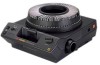
PROJECTOR LAMP LAMP EJECTOR LAMP SOCKET TERMINAL ASSEMBLY Important The EXTRA BRIGHT LAMP MODULE ...Remove the SCREW from the LAMP DOOR PLATE ASSEMBLY. [5] Release the 2 TABS on a cold surface; Do not set the parts on a clean cloth. TAB (2) CONDENSER LENS HEAT ABSORBING GLASS A091_0018CCA A091_0018CA Installing the LAMP SOCKET TERMINAL ASSEMBLY [1] Do the... the CONDENSER LENS and HEAT ABSORBING GLASS and set on the bottom side of the LAMP MODULE next to the parts. [7] Remove the LAMP EJECTOR. [8] Remove the LAMP SOCKET TERMINAL ASSEMBLY. SERVICE MANUAL Replacing the LAMP SOCKET TERMINAL...
PROJECTOR LAMP LAMP EJECTOR LAMP SOCKET TERMINAL ASSEMBLY Important The EXTRA BRIGHT LAMP MODULE ...Remove the SCREW from the LAMP DOOR PLATE ASSEMBLY. [5] Release the 2 TABS on a cold surface; Do not set the parts on a clean cloth. TAB (2) CONDENSER LENS HEAT ABSORBING GLASS A091_0018CCA A091_0018CA Installing the LAMP SOCKET TERMINAL ASSEMBLY [1] Do the... the CONDENSER LENS and HEAT ABSORBING GLASS and set on the bottom side of the LAMP MODULE next to the parts. [7] Remove the LAMP EJECTOR. [8] Remove the LAMP SOCKET TERMINAL ASSEMBLY. SERVICE MANUAL Replacing the LAMP SOCKET TERMINAL...

Service Manual
Page 36
SERVICE MANUAL Section 3: Lubrication Apply lubricant SUPER LUBE TL-4276 to the following parts and areas of the projector; SM5440-1 see the illustrations. • FAN • INDEXER LEVER and TOP PLATE • WORM PULLEY ASSEMBLY • CAM STACK ASSEMBLY • CYCLE LEVERS • PIVOT SHAFT and LEVERS • LENS MOUNT ASSEMBLY A091_4037GA 36 18NOV97 -
SERVICE MANUAL Section 3: Lubrication Apply lubricant SUPER LUBE TL-4276 to the following parts and areas of the projector; SM5440-1 see the illustrations. • FAN • INDEXER LEVER and TOP PLATE • WORM PULLEY ASSEMBLY • CAM STACK ASSEMBLY • CYCLE LEVERS • PIVOT SHAFT and LEVERS • LENS MOUNT ASSEMBLY A091_4037GA 36 18NOV97 -

Service Manual
Page 39
FAN COVER TOOL 11.5 cm (4.5 in.) A091_0024GCA A091_0024GA SM5440-1 - 18NOV97 39 To operate the projector with the LOWER HOUSING removed, make a FAN COVER TOOL. Section 4: Tools Tools TL-1744 TL-2264 TL-3002 TL-3003 TL-3005 TL-3255 TL-4276 Tool Description AUTO-FOCUS GAUGE FOCUS TEST (flat field) AUTO-FOCUS TARGET SLIDE ADJUSTMENT T-BAR ADJUSTMENT TOOL Torx DRIVER SET SUPER LUBE DIGITAL MULTIMETER Tools The LOWER HOUSING ASSEMBLY is a part of the cooling function. Cut here.
FAN COVER TOOL 11.5 cm (4.5 in.) A091_0024GCA A091_0024GA SM5440-1 - 18NOV97 39 To operate the projector with the LOWER HOUSING removed, make a FAN COVER TOOL. Section 4: Tools Tools TL-1744 TL-2264 TL-3002 TL-3003 TL-3005 TL-3255 TL-4276 Tool Description AUTO-FOCUS GAUGE FOCUS TEST (flat field) AUTO-FOCUS TARGET SLIDE ADJUSTMENT T-BAR ADJUSTMENT TOOL Torx DRIVER SET SUPER LUBE DIGITAL MULTIMETER Tools The LOWER HOUSING ASSEMBLY is a part of the cooling function. Cut here.

Service Manual
Page 46
... can cause binds. 1. See the Voltage chart. 1. Check for the following: • correct alignment of the CYCLE LEVER • damage to parts • lubrication of the CYCLE LEVER (use SUPER LUBE TL-4276) 3. Check the CYCLE LEVER and RATCHET LEVER on the CAM SHAFT ASSEMBLY for...Malfunction Forward and reverse do not operate using the FRONT PANEL BUTTONS or REMOTE CONTROL. Clean and lubricate the parts as necessary. If there is within the CAM. 1. Projector has continual cycle. Forward does not operate, reverse operates, voltages are correct. Check that the CYCLE LEVER ...
... can cause binds. 1. See the Voltage chart. 1. Check for the following: • correct alignment of the CYCLE LEVER • damage to parts • lubrication of the CYCLE LEVER (use SUPER LUBE TL-4276) 3. Check the CYCLE LEVER and RATCHET LEVER on the CAM SHAFT ASSEMBLY for...Malfunction Forward and reverse do not operate using the FRONT PANEL BUTTONS or REMOTE CONTROL. Clean and lubricate the parts as necessary. If there is within the CAM. 1. Projector has continual cycle. Forward does not operate, reverse operates, voltages are correct. Check that the CYCLE LEVER ...

Service Manual
Page 48
... the DVM should measure 0 W. 5. Remove R3 and install a new 68K W 1/4 W RESISTOR (part 220040). 2. Check the FOCUS SHAFT SPRING for damage; Check the REMOTE CORD for the correct tension. 2. Energize the projector and move the TIMER to close the DARK SHUTTER. 4. Press the "FORWARD" or "REVERSE" BUTTONS ... does not operate After the FOCUS MOTOR energizes and moves, the FOCUS MOTOR oscillates. Energize the projector and release the DARK SHUTTER to check for damage and install a new part if necessary. 1. If there is correct. 48 18NOV97 - If this procedure does not correct ...
... the DVM should measure 0 W. 5. Remove R3 and install a new 68K W 1/4 W RESISTOR (part 220040). 2. Check the FOCUS SHAFT SPRING for damage; Check the REMOTE CORD for the correct tension. 2. Energize the projector and move the TIMER to close the DARK SHUTTER. 4. Press the "FORWARD" or "REVERSE" BUTTONS ... does not operate After the FOCUS MOTOR energizes and moves, the FOCUS MOTOR oscillates. Energize the projector and release the DARK SHUTTER to check for damage and install a new part if necessary. 1. If there is correct. 48 18NOV97 - If this procedure does not correct ...