
Service Manual
Page 1
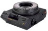
{ServiceManual}{Production}{KodakServiceSupport} Publication No. SM5440-1 18NOV97 Supersedes SM5440-1 13MAY97 SERVICE MANUAL Kodak Carousel PROJECTORS New Look PROJECTORS Kodak Home Page on Internet Models 4200, 4200-J, 4200-KK, 4400, 4600, 4600-KK, 5600, 5600-J, and 5600-KK Intranet Table of Contents © Eastman Kodak Company, 1999 A100_0029HA
{ServiceManual}{Production}{KodakServiceSupport} Publication No. SM5440-1 18NOV97 Supersedes SM5440-1 13MAY97 SERVICE MANUAL Kodak Carousel PROJECTORS New Look PROJECTORS Kodak Home Page on Internet Models 4200, 4200-J, 4200-KK, 4400, 4600, 4600-KK, 5600, 5600-J, and 5600-KK Intranet Table of Contents © Eastman Kodak Company, 1999 A100_0029HA

Service Manual
Page 2
... . . . . 17 Replacing the LAMP SOCKET TERMINAL ASSEMBLY 18 Installing the LAMP SOCKET TERMINAL ASSEMBLY 18 Replacing the LENS MOUNT ASSEMBLY - Eastman Kodak Company reserves the right to change this information without notice, and makes no warranty, express or implied, with Mechanism Out 27 2 18NOV97 - Auto... SHAFT ASSEMBLY 24 Adjustments 25 Adjusting the CYCLE SOLENOID 25 Adjusting the INDEXER LEVER ASSEMBLY 26 Adjusting the SLIDE LIFT LEVER MANUAL, with MECHANISM Out 27 Adjusting the SLIDE LIFT LEVER POWER with respect to this information, even if loss or damage is ...
... . . . . 17 Replacing the LAMP SOCKET TERMINAL ASSEMBLY 18 Installing the LAMP SOCKET TERMINAL ASSEMBLY 18 Replacing the LENS MOUNT ASSEMBLY - Eastman Kodak Company reserves the right to change this information without notice, and makes no warranty, express or implied, with Mechanism Out 27 2 18NOV97 - Auto... SHAFT ASSEMBLY 24 Adjustments 25 Adjusting the CYCLE SOLENOID 25 Adjusting the INDEXER LEVER ASSEMBLY 26 Adjusting the SLIDE LIFT LEVER MANUAL, with MECHANISM Out 27 Adjusting the SLIDE LIFT LEVER POWER with respect to this information, even if loss or damage is ...

Service Manual
Page 4
... HOUSING ASSEMBLY. [3] Cut the 3 WIRE TIES: • 1 on BLOWER COVER wires • 2 on SMALL CIRCUIT BOARD between the MOTOR and MECHANISM ASSEMBLY 4 18NOV97 - SM5440-1 SERVICE MANUAL Section 1: Replacements and Installations Replacing the LOWER HOUSING ASSEMBLY Warning Dangerous Voltage [1] Disconnect the main power. [2] Remove the PROJECTION LENS. [3] Remove the LAMP MODULE ASSEMBLY...
... HOUSING ASSEMBLY. [3] Cut the 3 WIRE TIES: • 1 on BLOWER COVER wires • 2 on SMALL CIRCUIT BOARD between the MOTOR and MECHANISM ASSEMBLY 4 18NOV97 - SM5440-1 SERVICE MANUAL Section 1: Replacements and Installations Replacing the LOWER HOUSING ASSEMBLY Warning Dangerous Voltage [1] Disconnect the main power. [2] Remove the PROJECTION LENS. [3] Remove the LAMP MODULE ASSEMBLY...

Service Manual
Page 6
SM5440-1 MOTOR SCREW RETAINER CLIP FAN FAN PLATE ASS4EMBLY FAN BELT MECHANISM BELT SCREW (2) BLOWER ASSEMBLY SCREW (3) Installing the FAN SHAFT ASSEMBLY A100_0014HCA A100_0014HA Important When installing the FAN and MECHANISM BELTS, install the MECHANISM BELT on the small MOTOR PULLEY, and the FAN BELT on the large MOTOR PULLEY. [1] Do the removal procedure for the FAN BELT and SHAFT in reverse order. FAN BELT MECHANISM BELT A091_4015BCA A091_4015BA 6 18NOV97 - SERVICE MANUAL [19] Lift and remove the FAN SHAFT ASSEMBLY.
SM5440-1 MOTOR SCREW RETAINER CLIP FAN FAN PLATE ASS4EMBLY FAN BELT MECHANISM BELT SCREW (2) BLOWER ASSEMBLY SCREW (3) Installing the FAN SHAFT ASSEMBLY A100_0014HCA A100_0014HA Important When installing the FAN and MECHANISM BELTS, install the MECHANISM BELT on the small MOTOR PULLEY, and the FAN BELT on the large MOTOR PULLEY. [1] Do the removal procedure for the FAN BELT and SHAFT in reverse order. FAN BELT MECHANISM BELT A091_4015BCA A091_4015BA 6 18NOV97 - SERVICE MANUAL [19] Lift and remove the FAN SHAFT ASSEMBLY.

Service Manual
Page 8
SM5440-1 SERVICE MANUAL FAN BELT MECHANISM BELT Replacing the WORM PULLEY and MECHANISM BELT A091_4015BCA A091_4015BA Warning Dangerous Voltage [1] Disconnect the main power. [2] Do the replacement procedure for the LOWER HOUSING ASSEMBLY. [3] Do the replacement procedure for the MOTOR except do not disconnect the wires from the MOTOR. [4] Remove the Torx SCREW from the WORM PULLEY ASSEMBLY. [5] Move the TAB on the WORM PULLEY ASSEMBLY out. [6] Remove the WORM PULLEY ASSEMBLY and MECHANISM BELT. 8 18NOV97 -
SM5440-1 SERVICE MANUAL FAN BELT MECHANISM BELT Replacing the WORM PULLEY and MECHANISM BELT A091_4015BCA A091_4015BA Warning Dangerous Voltage [1] Disconnect the main power. [2] Do the replacement procedure for the LOWER HOUSING ASSEMBLY. [3] Do the replacement procedure for the MOTOR except do not disconnect the wires from the MOTOR. [4] Remove the Torx SCREW from the WORM PULLEY ASSEMBLY. [5] Move the TAB on the WORM PULLEY ASSEMBLY out. [6] Remove the WORM PULLEY ASSEMBLY and MECHANISM BELT. 8 18NOV97 -

Service Manual
Page 10
SERVICE MANUAL Replacing the THERMAL FUSE ASSEMBLY Warning Dangerous Voltage [1] Disconnect the main power. [2] Do the replacement procedure for the THERMAL FUSE ASSEMBLY in reverse order. Installing ...
SERVICE MANUAL Replacing the THERMAL FUSE ASSEMBLY Warning Dangerous Voltage [1] Disconnect the main power. [2] Do the replacement procedure for the THERMAL FUSE ASSEMBLY in reverse order. Installing ...

Service Manual
Page 12
... TAB on the SMALL CIRCUIT BOARD. [5] Pull the SMALL CIRCUIT BOARD up and out. [11] If necessary, remove the CYCLE SOLENOID PLUNGER ASSEMBLY. SM5440-1 SERVICE MANUAL Replacing the CYCLE SOLENOID ASSEMBLY CYCLE SOLENOID CYCLE SOLENOID PLUNGER SCREW (2) A100_0017GCA A100_0017GA Warning Dangerous Voltage [1] Disconnect the main power. [2] Do the replacement procedures for...
... TAB on the SMALL CIRCUIT BOARD. [5] Pull the SMALL CIRCUIT BOARD up and out. [11] If necessary, remove the CYCLE SOLENOID PLUNGER ASSEMBLY. SM5440-1 SERVICE MANUAL Replacing the CYCLE SOLENOID ASSEMBLY CYCLE SOLENOID CYCLE SOLENOID PLUNGER SCREW (2) A100_0017GCA A100_0017GA Warning Dangerous Voltage [1] Disconnect the main power. [2] Do the replacement procedures for...

Service Manual
Page 14
... LINK from the AUTO-FOCUS BRACKET ASSEMBLY. [12] Pull and remove the AUTO-FOCUS BRACKET ASSEMBLY through the hole where the CYCLE SOLENOID was. SERVICE MANUAL Replacing the AUTO-FOCUS BRACKET ASSEMBLY Warning Dangerous Voltage [1] Disconnect the main power. [2] Do the replacement procedure for the LOWER HOUSING ASSEMBLY. [3] Cut and remove...
... LINK from the AUTO-FOCUS BRACKET ASSEMBLY. [12] Pull and remove the AUTO-FOCUS BRACKET ASSEMBLY through the hole where the CYCLE SOLENOID was. SERVICE MANUAL Replacing the AUTO-FOCUS BRACKET ASSEMBLY Warning Dangerous Voltage [1] Disconnect the main power. [2] Do the replacement procedure for the LOWER HOUSING ASSEMBLY. [3] Cut and remove...

Service Manual
Page 16
SERVICE MANUAL SELECT LEVER LIFT LEVER LIFT LEVER SHAFT E-RING SELECT LEVER SPRING BEARING CAM STACK ASSEMBLY TAB E-RING NUT BEARING A091_0010HCA A091_0010HA 16 18NOV97 - SM5440-1
SERVICE MANUAL SELECT LEVER LIFT LEVER LIFT LEVER SHAFT E-RING SELECT LEVER SPRING BEARING CAM STACK ASSEMBLY TAB E-RING NUT BEARING A091_0010HCA A091_0010HA 16 18NOV97 - SM5440-1

Service Manual
Page 18
this will cause damage to the LAMP MODULE DOOR. [6] Remove the LAMP DOOR PLATE ASSEMBLY. SERVICE MANUAL Replacing the LAMP SOCKET TERMINAL ASSEMBLY Style 1 LAMP SOCKET TERMINAL ASSEMBLY SCREW LAMP DOOR PLATE ASSEMBLY Warning Dangerous Voltage [1] Disconnect the main power. SM5440-1 Do ...
this will cause damage to the LAMP MODULE DOOR. [6] Remove the LAMP DOOR PLATE ASSEMBLY. SERVICE MANUAL Replacing the LAMP SOCKET TERMINAL ASSEMBLY Style 1 LAMP SOCKET TERMINAL ASSEMBLY SCREW LAMP DOOR PLATE ASSEMBLY Warning Dangerous Voltage [1] Disconnect the main power. SM5440-1 Do ...

Service Manual
Page 20
Non Auto Focus Model [1] Do the replacement procedure for the LOWER HOUSING ASSEMBLY. [3] Remove the FOCUS KNOB. [4] Remove the 3 SCREWS from the LENS MOUNT ASSEMBLY. [5] Lift and remove the LENS MOUNT ASSEMBLY. Non Auto Focus Model LENS MOUNT ASSEMBLY SCREW (3) Warning Dangerous Voltage [1] Disconnect the main power. [2] Do the replacement procedure for the LENS MOUNT ASSEMBLY in reverse order. 20 18NOV97 - A100_0019GCA A100_0019GA Installing the LENS MOUNT ASSEMBLY - SM5440-1 SERVICE MANUAL Replacing the LENS MOUNT ASSEMBLY -
Non Auto Focus Model [1] Do the replacement procedure for the LOWER HOUSING ASSEMBLY. [3] Remove the FOCUS KNOB. [4] Remove the 3 SCREWS from the LENS MOUNT ASSEMBLY. [5] Lift and remove the LENS MOUNT ASSEMBLY. Non Auto Focus Model LENS MOUNT ASSEMBLY SCREW (3) Warning Dangerous Voltage [1] Disconnect the main power. [2] Do the replacement procedure for the LENS MOUNT ASSEMBLY in reverse order. 20 18NOV97 - A100_0019GCA A100_0019GA Installing the LENS MOUNT ASSEMBLY - SM5440-1 SERVICE MANUAL Replacing the LENS MOUNT ASSEMBLY -

Service Manual
Page 22
SM5440-1 SERVICE MANUAL [2] Do the replacement procedure for the LOWER HOUSING ASSEMBLY. [3] Remove the FOCUS KNOB. CLAMP LEVER SPRING SCREW FOCUS SHAFT SPRING RACK LEVER (not shown) FOCUS ...
SM5440-1 SERVICE MANUAL [2] Do the replacement procedure for the LOWER HOUSING ASSEMBLY. [3] Remove the FOCUS KNOB. CLAMP LEVER SPRING SCREW FOCUS SHAFT SPRING RACK LEVER (not shown) FOCUS ...

Service Manual
Page 24
SM5440-1 SERVICE MANUAL Installing the FOCUS SHAFT ASSEMBLY [1] Do the replacement procedure for the FOCUS SHAFT ASSEMBLY in reverse order. 24 18NOV97 -
SM5440-1 SERVICE MANUAL Installing the FOCUS SHAFT ASSEMBLY [1] Do the replacement procedure for the FOCUS SHAFT ASSEMBLY in reverse order. 24 18NOV97 -
Service Manual
Page 26
SERVICE MANUAL Adjustment Specification This adjustment adjusts the strobe and timing of TL-3001. 26 18NOV97 - MECHANISM RUNNING FIXTURE position 1 position 2 A091_0008HCA A091_0008HA Adjustment Speci&#...
SERVICE MANUAL Adjustment Specification This adjustment adjusts the strobe and timing of TL-3001. 26 18NOV97 - MECHANISM RUNNING FIXTURE position 1 position 2 A091_0008HCA A091_0008HA Adjustment Speci&#...

Service Manual
Page 27
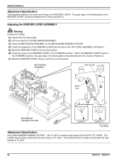
... LEVER down to move the SLIDE LIFT LEVER to the highest position. [5] Measure the height of the SLIDE LIFT LEVER. Adjusting the SLIDE LIFT LEVER MANUAL, with MECHANISM Out Adjustments Warning Dangerous Voltage [1] Disconnect the main power. [2] Do the removal for the MECHANISM ASSEMBLY. [3] Place the MECHANISM ASSEMBLY on the MECHANISM...
... LEVER down to move the SLIDE LIFT LEVER to the highest position. [5] Measure the height of the SLIDE LIFT LEVER. Adjusting the SLIDE LIFT LEVER MANUAL, with MECHANISM Out Adjustments Warning Dangerous Voltage [1] Disconnect the main power. [2] Do the removal for the MECHANISM ASSEMBLY. [3] Place the MECHANISM ASSEMBLY on the MECHANISM...

Service Manual
Page 28
... to make a FAN COVER TOOL. Warning Dangerous Voltage [1] Disconnect the main power. [2] Remove the PROJECTION LENS. [3] Do the removal for the LOWER HOUSING ASSEMBLY. SERVICE MANUAL SLIDE LIFT LEVER GUAGE TL-3001 SLIDE LIFT LEVER SELECT LEVER (not shown) A091_0016BCA A091_0016BA Adjusting the Focus Light Path -
... to make a FAN COVER TOOL. Warning Dangerous Voltage [1] Disconnect the main power. [2] Remove the PROJECTION LENS. [3] Do the removal for the LOWER HOUSING ASSEMBLY. SERVICE MANUAL SLIDE LIFT LEVER GUAGE TL-3001 SLIDE LIFT LEVER SELECT LEVER (not shown) A091_0016BCA A091_0016BA Adjusting the Focus Light Path -
Service Manual
Page 30
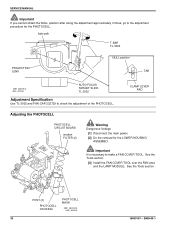
... (2) Warning Dangerous Voltage [1] Disconnect the main power. [2] Do the removal for the PHOTOCELL. Important It is necessary to check the adjustment of the PHOTOCELL. SERVICE MANUAL Important If you cannot obtain the NULL position after doing the adjustment approximately 3 times, go to the adjustment procedure for the LOWER HOUSING ASSEMBLY. light...
... (2) Warning Dangerous Voltage [1] Disconnect the main power. [2] Do the removal for the PHOTOCELL. Important It is necessary to check the adjustment of the PHOTOCELL. SERVICE MANUAL Important If you cannot obtain the NULL position after doing the adjustment approximately 3 times, go to the adjustment procedure for the LOWER HOUSING ASSEMBLY. light...

Service Manual
Page 32
Important It is fully seated in the NULL position. light image FAN CAP A091_4033GCA A091_4033GA [12] Manually move the CLAMP PAD ASSEMBLY until it is necessary to make a FAN COVER TOOL. See the Tools section. [15] Install and hold the AUTO FOCUS ... area and the LAMP MODULE. SM5440-1 light path NULL position TAB A091_4027BCA A091_4027BA CLAMP LEVER PAD Warning Dangerous Voltage [13] Connect the main power. SERVICE MANUAL hole FAN CAP [11] Install the FAN CAP 232729 in the PHOTOCELL HOUSING.
Important It is fully seated in the NULL position. light image FAN CAP A091_4033GCA A091_4033GA [12] Manually move the CLAMP PAD ASSEMBLY until it is necessary to make a FAN COVER TOOL. See the Tools section. [15] Install and hold the AUTO FOCUS ... area and the LAMP MODULE. SM5440-1 light path NULL position TAB A091_4027BCA A091_4027BA CLAMP LEVER PAD Warning Dangerous Voltage [13] Connect the main power. SERVICE MANUAL hole FAN CAP [11] Install the FAN CAP 232729 in the PHOTOCELL HOUSING.
Service Manual
Page 34
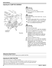
...-1744. Warning Dangerous Voltage [5] Connect the main power. [6] Loosen the NUT on the CLAMP PAD ASSEMBLY. [7] Energize the REMOTE FOCUS in the MECHANISM GATE. SERVICE MANUAL Adjusting the CLAMP PAD ASSEMBLY SCREW NUT CLAMP PAD ASSEMBLY A091_4041GCA A091_4041GA Warning Dangerous Voltage [1] Disconnect the main power. [2] Do the removal for the LOWER...
...-1744. Warning Dangerous Voltage [5] Connect the main power. [6] Loosen the NUT on the CLAMP PAD ASSEMBLY. [7] Energize the REMOTE FOCUS in the MECHANISM GATE. SERVICE MANUAL Adjusting the CLAMP PAD ASSEMBLY SCREW NUT CLAMP PAD ASSEMBLY A091_4041GCA A091_4041GA Warning Dangerous Voltage [1] Disconnect the main power. [2] Do the removal for the LOWER...

Service Manual
Page 36
SERVICE MANUAL Section 3: Lubrication Apply lubricant SUPER LUBE TL-4276 to the following parts and areas of the projector; see the illustrations. • FAN • INDEXER LEVER and TOP PLATE • WORM PULLEY ASSEMBLY • CAM STACK ASSEMBLY • CYCLE LEVERS • PIVOT SHAFT and LEVERS • LENS MOUNT ASSEMBLY A091_4037GA 36 18NOV97 - SM5440-1
SERVICE MANUAL Section 3: Lubrication Apply lubricant SUPER LUBE TL-4276 to the following parts and areas of the projector; see the illustrations. • FAN • INDEXER LEVER and TOP PLATE • WORM PULLEY ASSEMBLY • CAM STACK ASSEMBLY • CYCLE LEVERS • PIVOT SHAFT and LEVERS • LENS MOUNT ASSEMBLY A091_4037GA 36 18NOV97 - SM5440-1