Owners Manual
Page 5
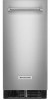
... In U.S.A., order Part Number W10355016 In Canada, order Part Number W10355010B In Canada, order Part Number W10355016B TROUBLESHOOTING Visit producthelp.kitchenaid.com for the drain pump to the water pan. Do not remove ground prong. See "Using the Controls." If there is securely attached to clear.... ice maker, wait a few minutes for recommendations that were removed from the water during which water filling associated with drain pumps, check that the drain hose is not damaged, or kinked or pinched between the evaporator plate and the cutting grid, check that it off...
... In U.S.A., order Part Number W10355016 In Canada, order Part Number W10355010B In Canada, order Part Number W10355016B TROUBLESHOOTING Visit producthelp.kitchenaid.com for the drain pump to the water pan. Do not remove ground prong. See "Using the Controls." If there is securely attached to clear.... ice maker, wait a few minutes for recommendations that were removed from the water during which water filling associated with drain pumps, check that the drain hose is not damaged, or kinked or pinched between the evaporator plate and the cutting grid, check that it off...
Specification Sheet
Page 1
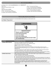
... U.S.A. Clear Ice Technology Helps produce cubes of Ice Max Ice PrintShield™ Finish (KUIX335HPS only) Filter-Ready Reversible Door Electrical Details Amps 15 or 20 Volts 115/120 Technical Details Ice Maker Type Control Location Ice Capacity Storage (lbs) Drain Pump Installation Option Lighting Type Dimensions Product Dimensions (H x W x D) Depth with Door Open 90...
... U.S.A. Clear Ice Technology Helps produce cubes of Ice Max Ice PrintShield™ Finish (KUIX335HPS only) Filter-Ready Reversible Door Electrical Details Amps 15 or 20 Volts 115/120 Technical Details Ice Maker Type Control Location Ice Capacity Storage (lbs) Drain Pump Installation Option Lighting Type Dimensions Product Dimensions (H x W x D) Depth with Door Open 90...
Installation Instructions
Page 1
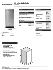
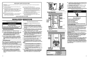
... 20 Exigences d'emplacement 20 Spécifications électriques 21 Spécifications de l'alimentation en eau 22 Exigences concernant le raccordement au drain 22 Inversion de la porte 23 Installation de la pompe de vidange (sur certains modèles 26 Raccordement à la canalisation d'eau... ICE MAKER SAFETY 1 INSTALLATION INSTRUCTIONS 2 Unpack the Ice Maker 2 Vacation or Extended Time Without Use 2 Location Requirements 2 Electrical Requirements 3 Water Supply Requirements 4 Drain Connection Requirements 4 Door Reversal 5 Drain Pump Installation (on your appliance.
... 20 Exigences d'emplacement 20 Spécifications électriques 21 Spécifications de l'alimentation en eau 22 Exigences concernant le raccordement au drain 22 Inversion de la porte 23 Installation de la pompe de vidange (sur certains modèles 26 Raccordement à la canalisation d'eau... ICE MAKER SAFETY 1 INSTALLATION INSTRUCTIONS 2 Unpack the Ice Maker 2 Vacation or Extended Time Without Use 2 Location Requirements 2 Electrical Requirements 3 Water Supply Requirements 4 Drain Connection Requirements 4 Door Reversal 5 Drain Pump Installation (on your appliance.
Installation Instructions
Page 2
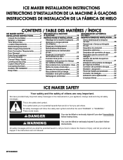
...ice maker, be provided. Before you have been designed for flush install in instances where the power supply, water supply, and drain are located in accordance with the National Electrical Code and local codes and ordinances. See the cleaning instructions in accordance with the ...) OD soft copper tubing with a shutoff valve or a Whirlpool supply line Part Number 8212547RB, and a Whirlpool approved drain pump, Part Number 1901A, only to carry the water to an existing drain. ■ Choose a well-ventilated area with temperatures above 55°F (13°C) and below it is required...
...ice maker, be provided. Before you have been designed for flush install in instances where the power supply, water supply, and drain are located in accordance with the National Electrical Code and local codes and ordinances. See the cleaning instructions in accordance with the ...) OD soft copper tubing with a shutoff valve or a Whirlpool supply line Part Number 8212547RB, and a Whirlpool approved drain pump, Part Number 1901A, only to carry the water to an existing drain. ■ Choose a well-ventilated area with temperatures above 55°F (13°C) and below it is required...
Installation Instructions
Page 3
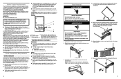
... capacity reverse osmosis system, capable of maintaining the steady water supply required by the warranty. Damage from backing up into the ice maker. ■ Drain pump maximum capability: For every 1 ft (0.31 m) of rise, subtract 10 ft (3.1 m) of maximum allowable run and must be used on the door...to see whether the sediment filter in accordance with the International Plumbing Code and any local codes and ordinances. ■ The drain pump discharge line must terminate at an open-site drain. ■ Maximum rise 10 ft (3.1 m) ■ Maximum run or 1/4" drop per 12" (6.35 mm per hour...
... capacity reverse osmosis system, capable of maintaining the steady water supply required by the warranty. Damage from backing up into the ice maker. ■ Drain pump maximum capability: For every 1 ft (0.31 m) of rise, subtract 10 ft (3.1 m) of maximum allowable run and must be used on the door...to see whether the sediment filter in accordance with the International Plumbing Code and any local codes and ordinances. ■ The drain pump discharge line must terminate at an open-site drain. ■ Maximum rise 10 ft (3.1 m) ■ Maximum run or 1/4" drop per 12" (6.35 mm per hour...
Installation Instructions
Page 5
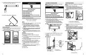
...to 10 minutes for the ice to follow these instructions can result in step 17). Drain cap 5. Unplug ice maker or disconnect power. 2. Mounting tab slot Drain Pump Installed A A. Drain pump installed 9 Do not use an extension cord. Plug into the storage bin. WARNING.... Ferrule (sleeve) E. 5. Replace all ice from the magnetic door catch and place them on some models) NOTES: ■ Connect drain pump to "Drain Pump Installation" section. 1. For custom door panel, skip this step. Remove the screws from bin. 4. For standard model discard the rear ...
...to 10 minutes for the ice to follow these instructions can result in step 17). Drain cap 5. Unplug ice maker or disconnect power. 2. Mounting tab slot Drain Pump Installed A A. Drain pump installed 9 Do not use an extension cord. Plug into the storage bin. WARNING.... Ferrule (sleeve) E. 5. Replace all ice from the magnetic door catch and place them on some models) NOTES: ■ Connect drain pump to "Drain Pump Installation" section. 1. For custom door panel, skip this step. Remove the screws from bin. 4. For standard model discard the rear ...
Installation Instructions
Page 6
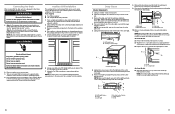
...water supply. 5. See "Parts Locations" illustration. 6. Parts Locations Vent Tube NOTE: Do not pinch, kink or damage the vent tube. Drain pump discharge tube D. Drain pump power cord, clamp and screw H. NOTE: Clamp and screw will remain above freezing. See "Parts Locations" illustration. 13. NOTES: ■...removed in illustration. Install the cable tie on copper tubing as shown in Step 6) that is located behind the wiring cover. Drain pump E. Remove wiring cover. Remove power cord clamp and ground screw attached to the unit base. Screws 8. NOTE: To allow sufficient...
...water supply. 5. See "Parts Locations" illustration. 6. Parts Locations Vent Tube NOTE: Do not pinch, kink or damage the vent tube. Drain pump discharge tube D. Drain pump power cord, clamp and screw H. NOTE: Clamp and screw will remain above freezing. See "Parts Locations" illustration. 13. NOTES: ■...removed in illustration. Install the cable tie on copper tubing as shown in Step 6) that is located behind the wiring cover. Drain pump E. Remove wiring cover. Remove power cord clamp and ground screw attached to the unit base. Screws 8. NOTE: To allow sufficient...
Installation Instructions
Page 9
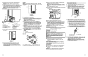
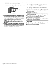
..., be sure the ice maker is positioned over the PVC drain reducer. Style 2-For a drain pump system, connect the drain pump outlet hose to be sure that the ice maker drain tube is operating properly. 4. Place grill onto cabinetry. Electrical Shock Hazard Plug into cabinet. Wait for ice maker. This is ... from the water pan, and you will empty from the water pan and unplug the water pan drain pump. Drain pump cover 10. A B A A. Lift the cutter grid up into the cabinet. Cutter grid harness B. Failure to follow these instructions can result in death,...
..., be sure the ice maker is positioned over the PVC drain reducer. Style 2-For a drain pump system, connect the drain pump outlet hose to be sure that the ice maker drain tube is operating properly. 4. Place grill onto cabinetry. Electrical Shock Hazard Plug into cabinet. Wait for ice maker. This is ... from the water pan, and you will empty from the water pan and unplug the water pan drain pump. Drain pump cover 10. A B A A. Lift the cutter grid up into the cabinet. Cutter grid harness B. Failure to follow these instructions can result in death,...
Installation Instructions
Page 10
...They cannot withstand temperatures above 145°F (63°C). 12. Hook up the water pan pump. ■ Wash the ice scoop holder along with the other interior components using the following : ■ Drain cap from the water pan is securely in place. Ice scoop holder 11. Reconnect the cutter ...grid harness and the ice level sensor harness. 15. We recommend using warm water and a mild liquid dish detergent. 17. A A. Snap the pump bracket back onto the water...
...They cannot withstand temperatures above 145°F (63°C). 12. Hook up the water pan pump. ■ Wash the ice scoop holder along with the other interior components using the following : ■ Drain cap from the water pan is securely in place. Ice scoop holder 11. Reconnect the cutter ...grid harness and the ice level sensor harness. 15. We recommend using warm water and a mild liquid dish detergent. 17. A A. Snap the pump bracket back onto the water...


