
Owners Manual
Page 1
... read and obey all parts and panels before operating. User Guide Ice Maker LEARN MORE In an effort to conserve natural resources, this manual and on the inside of others . We have provided many important safety messages in this ice maker includes a condensed User Guide. All safety messages will follow instructions. Do not remove ground prong. Disconnect power before servicing. Replace all safety messages. Do...
... read and obey all parts and panels before operating. User Guide Ice Maker LEARN MORE In an effort to conserve natural resources, this manual and on the inside of others . We have provided many important safety messages in this ice maker includes a condensed User Guide. All safety messages will follow instructions. Do not remove ground prong. Disconnect power before servicing. Replace all safety messages. Do...
Owners Manual
Page 2
... cubes. OPERATING YOUR ICE MAKER How Your Ice Maker Works When you first start ice production, press ON/OFF. 2. The Ice Making Process 1. To start your ice maker, see "Ice Maker System" in the ice storage bin will cycle at preset temperatures. O-rings D C. Under normal operating conditions, the ice maker will monitor the ice levels. The ice level sensor located in the "Cleaning" section. Water is released and slides onto a cutter grid. As the water freezes into ice...
... cubes. OPERATING YOUR ICE MAKER How Your Ice Maker Works When you first start ice production, press ON/OFF. 2. The Ice Making Process 1. To start your ice maker, see "Ice Maker System" in the ice storage bin will cycle at preset temperatures. O-rings D C. Under normal operating conditions, the ice maker will monitor the ice levels. The ice level sensor located in the "Cleaning" section. Water is released and slides onto a cutter grid. As the water freezes into ice...

Owners Manual
Page 3
...) models, push the control box door closed . Install the replacement water filter by the condenser fan. ■■ During the harvest cycle, you may hear a "thud" when the ice sheet slides from the evaporator onto the cutter grid. ■■ When you first start the ice maker, you know when to order a replacement filter. ■■ The "Replace Filter" status light will be some water in the "Install the Water Filter...
...) models, push the control box door closed . Install the replacement water filter by the condenser fan. ■■ During the harvest cycle, you may hear a "thud" when the ice sheet slides from the evaporator onto the cutter grid. ■■ When you first start the ice maker, you know when to order a replacement filter. ■■ The "Replace Filter" status light will be some water in the "Install the Water Filter...
Owners Manual
Page 5
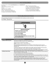
... drain pumps, check that the drain hose is not damaged, or kinked or pinched between the evaporator plate and the cutting grid, check that the water supply is plugged into a grounded 3 prong outlet. Use only Whirlpool approved drain pump kit, Part Number 1901A. This overflow helps to purge minerals that the drain cap is tight and the water drain pan pump is ice between cabinet and ice maker. For models...
... drain pumps, check that the drain hose is not damaged, or kinked or pinched between the evaporator plate and the cutting grid, check that the water supply is plugged into a grounded 3 prong outlet. Use only Whirlpool approved drain pump kit, Part Number 1901A. This overflow helps to purge minerals that the drain cap is tight and the water drain pan pump is ice between cabinet and ice maker. For models...
Owners Manual
Page 6
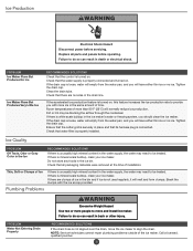
... is not aligned over the drain, move and install ice maker. Break the clumps with more ice in the ice maker's water or freezing system, you will melt and form clumps. PROBLEM Water Not Entering Drain Properly RECOMMENDED SOLUTIONS If the drain hose is mineral scale buildup, clean your ice maker. If the drain cap is turned on . NOTE: Service technicians cannot repair plumbing problems outside of time. Replace all packaging materials were...
... is not aligned over the drain, move and install ice maker. Break the clumps with more ice in the ice maker's water or freezing system, you will melt and form clumps. PROBLEM Water Not Entering Drain Properly RECOMMENDED SOLUTIONS If the drain hose is mineral scale buildup, clean your ice maker. If the drain cap is turned on . NOTE: Service technicians cannot repair plumbing problems outside of time. Replace all packaging materials were...

Owners Manual
Page 8
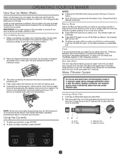
... or plumbing codes, or correction of purchase, including dealer or retailer name and address IF YOU NEED SERVICE: 1. Service or parts for service or repair of this major appliance, you call the Customer eXperience Center: Name, address, and telephone number Model number and serial number A clear, detailed description of the problem Proof of household electrical or plumbing (e.g., house wiring, fuses, or water inlet hoses). 4. Cosmetic damage...
... or plumbing codes, or correction of purchase, including dealer or retailer name and address IF YOU NEED SERVICE: 1. Service or parts for service or repair of this major appliance, you call the Customer eXperience Center: Name, address, and telephone number Model number and serial number A clear, detailed description of the problem Proof of household electrical or plumbing (e.g., house wiring, fuses, or water inlet hoses). 4. Cosmetic damage...
Installation Instructions
Page 1
...;NDICE ICE MAKER SAFETY 1 INSTALLATION INSTRUCTIONS 2 Unpack the Ice Maker 2 Vacation or Extended Time Without Use 2 Location Requirements 2 Electrical Requirements 3 Water Supply Requirements 4 Drain Connection Requirements 4 Door Reversal 5 Drain Pump Installation (on your appliance. We have provided many important safety messages in this manual and on some models 8 Connect Water Supply 11 Leveling and Securing 12 Custom Wood Panel 14 Connecting the Drain 16 Auxiliary Grill Installation 16 Deep Clean 17...
...;NDICE ICE MAKER SAFETY 1 INSTALLATION INSTRUCTIONS 2 Unpack the Ice Maker 2 Vacation or Extended Time Without Use 2 Location Requirements 2 Electrical Requirements 3 Water Supply Requirements 4 Drain Connection Requirements 4 Door Reversal 5 Drain Pump Installation (on your appliance. We have provided many important safety messages in this manual and on some models 8 Connect Water Supply 11 Leveling and Securing 12 Custom Wood Panel 14 Connecting the Drain 16 Auxiliary Grill Installation 16 Deep Clean 17...
Installation Instructions
Page 2
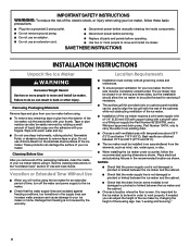
... the water supply line is even. Location Requirements ■■ Installation must comply with all parts and panels before using. ■■ To remove any remaining tape or glue from freezing is important for the ice maker to be using the ice maker for servicing if necessary. ■■ The auxiliary grill kit provided (only on custom panel models) can damage the surface of your ice maker. See "Leveling...
... the water supply line is even. Location Requirements ■■ Installation must comply with all parts and panels before using. ■■ To remove any remaining tape or glue from freezing is important for the ice maker to be using the ice maker for servicing if necessary. ■■ The auxiliary grill kit provided (only on custom panel models) can damage the surface of your ice maker. See "Leveling...
Installation Instructions
Page 3
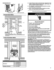
... codes and ordinances. Floor level Custom Panel Model Utilities Required zone for electrical and plumbing fixtures B. Model Identification: Standard model Standard Model Utilities Custom panel model ■■ Custom Panel ice maker models have been designed for flush install in instances where the power supply, water supply, and drain are located in adjacent cabinetry. ■■ For installation of product with utilities behind the ice maker, flush install may not be turned...
... codes and ordinances. Floor level Custom Panel Model Utilities Required zone for electrical and plumbing fixtures B. Model Identification: Standard model Standard Model Utilities Custom panel model ■■ Custom Panel ice maker models have been designed for flush install in instances where the power supply, water supply, and drain are located in adjacent cabinetry. ■■ For installation of product with utilities behind the ice maker, flush install may not be turned...
Installation Instructions
Page 4
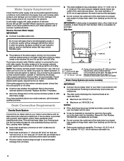
... kit, Part Number W10365792, is not covered by the warranty. A cold water supply with all drains. 17/8" (4.8 cm) 23" (58.4 cm) A B 1" (2.54 cm) C D A. IMPORTANT: A drain pump is necessary when a floor drain is blocked. This will not work. ■■ It may contain filterable cysts. ■■ The pressure of the water supply coming out of a reverse osmosis system going to the water inlet valve of the ice maker). Water...
... kit, Part Number W10365792, is not covered by the warranty. A cold water supply with all drains. 17/8" (4.8 cm) 23" (58.4 cm) A B 1" (2.54 cm) C D A. IMPORTANT: A drain pump is necessary when a floor drain is blocked. This will not work. ■■ It may contain filterable cysts. ■■ The pressure of the water supply coming out of a reverse osmosis system going to the water inlet valve of the ice maker). Water...
Installation Instructions
Page 7
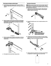
...onto the door. 2. Place the steel door panel back on the door once all installed parts to original locations on , and the door is now the bottom left end cap and vice versa). Final Door Placement NOTE: Before placing the door back on the ice maker, check ...all screws are on the hinges. Take the original top hinge, flip it and place it in the bottom hinge position on the opposite side. A 2. Install the hinge screws (placed aside in the step 6 of the cabinet. Using Torx T25 screwdriver install the screws (removed in step 10 of "Door Panel...
...onto the door. 2. Place the steel door panel back on the door once all installed parts to original locations on , and the door is now the bottom left end cap and vice versa). Final Door Placement NOTE: Before placing the door back on the ice maker, check ...all screws are on the hinges. Take the original top hinge, flip it and place it in the bottom hinge position on the opposite side. A 2. Install the hinge screws (placed aside in the step 6 of the cabinet. Using Torx T25 screwdriver install the screws (removed in step 10 of "Door Panel...
Installation Instructions
Page 8
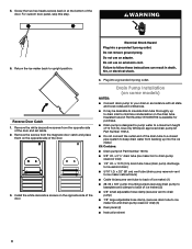
... drain pump kit Part Number 1901A. ■■ Do not connect the outlet end of the door. 3. Do not use an adapter. Plug into a grounded 3 prong outlet. Electrical Shock Hazard Plug into a grounded 3 prong outlet. Kit Contains: ■■ Drain pump kit Part Number 1901A ■■ 5/8" I.D. 5. Remove the white decorative screws from backing up to drain inlet to ice maker bin and drain pump reservoir inlet) (3) ■■ Rear panel (2) ■■ Instruction sheet 8 Drain Pump Installation...
... drain pump kit Part Number 1901A. ■■ Do not connect the outlet end of the door. 3. Do not use an adapter. Plug into a grounded 3 prong outlet. Electrical Shock Hazard Plug into a grounded 3 prong outlet. Kit Contains: ■■ Drain pump kit Part Number 1901A ■■ 5/8" I.D. 5. Remove the white decorative screws from backing up to drain inlet to ice maker bin and drain pump reservoir inlet) (3) ■■ Rear panel (2) ■■ Instruction sheet 8 Drain Pump Installation...
Installation Instructions
Page 9
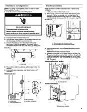
... Shock Hazard Disconnect power before operating. Drain Cap A A. Push the selector switch to slip into the storage bin. Replace all ice from bin. 4. Turn off water supply. Screw locations for the ice to do so can result in the ice maker base. Water Supply Line A B C B D C E A. 1/4" copper tubing B. Unplug ice maker or disconnect power. 3. Allow water to drain completely. Drain cap 5. Ice maker connection Drain Pump Installation NOTE: Do not kink, smash or damage tubes or wires during installation. 1.
... Shock Hazard Disconnect power before operating. Drain Cap A A. Push the selector switch to slip into the storage bin. Replace all ice from bin. 4. Turn off water supply. Screw locations for the ice to do so can result in the ice maker base. Water Supply Line A B C B D C E A. 1/4" copper tubing B. Unplug ice maker or disconnect power. 3. Allow water to drain completely. Drain cap 5. Ice maker connection Drain Pump Installation NOTE: Do not kink, smash or damage tubes or wires during installation. 1.
Installation Instructions
Page 10
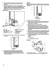
... ice maker bin to drain pump) D. Screws 8. Using cable tie, tie the vent tube to attach ice maker power cord. Refer "Vent Tube" illustration. NOTE: Do not install household drain tube this time. A B A. Wrap electrical tape around the power cord in a coil. Parts Locations Vent Tube NOTE: Do not pinch, kink or damage the vent tube. Remove wiring cover. Vent tube B. Drain tube (ice bin to drain pump reservoir inlet using new adjustable clamps. Install vent tube (5/16" I . Drain pump discharge tube D. Wiring cover 7. See "Parts...
... ice maker bin to drain pump) D. Screws 8. Using cable tie, tie the vent tube to attach ice maker power cord. Refer "Vent Tube" illustration. NOTE: Do not install household drain tube this time. A B A. Wrap electrical tape around the power cord in a coil. Parts Locations Vent Tube NOTE: Do not pinch, kink or damage the vent tube. Remove wiring cover. Vent tube B. Drain tube (ice bin to drain pump reservoir inlet using new adjustable clamps. Install vent tube (5/16" I . Drain pump discharge tube D. Wiring cover 7. See "Parts...
Installation Instructions
Page 11
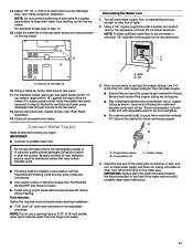
Connecting the Water Line 1. Turn on the rear panel. Secure rear panel with a quarter-turn on copper tubing as it will remain above freezing. Connect Water Supply Read all connections for leaks. ■■ Install tubing only in accordance with the International Plumbing Code and any local codes and ordinances. ■■ Use copper tubing or Whirlpool supply line, Part Number 8212547RP, and check for leaks. A. Compression nut C. Install the...
Connecting the Water Line 1. Turn on the rear panel. Secure rear panel with a quarter-turn on copper tubing as it will remain above freezing. Connect Water Supply Read all connections for leaks. ■■ Install tubing only in accordance with the International Plumbing Code and any local codes and ordinances. ■■ Use copper tubing or Whirlpool supply line, Part Number 8212547RP, and check for leaks. A. Compression nut C. Install the...
Installation Instructions
Page 12
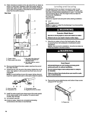
... water line inlet. 7. NOTE: To avoid rattling, be installed. Remove the screws attaching top and bottom hinge covers using an 3/16" hex driver. Check for the ice maker to follow these instructions can result in order to work properly. A A. Be sure to cover the floor with cardboard or hardboard to match with a wrench two more people to level it with water line inlet. Water supply tube...
... water line inlet. 7. NOTE: To avoid rattling, be installed. Remove the screws attaching top and bottom hinge covers using an 3/16" hex driver. Check for the ice maker to follow these instructions can result in order to work properly. A A. Be sure to cover the floor with cardboard or hardboard to match with a wrench two more people to level it with water line inlet. Water supply tube...

Installation Instructions
Page 17
... grid harness B. Disconnect the pump bracket from the right side of the cutter grid bracket stays with the other models, the ice scoop holder is loose, water will have either thin ice or no ice. 4. A B A. Deep Clean Interior Components 1. Replace the drain cap securely on other interior components using the following instructions. ■■ Replace the ice scoop holder by removing the 2 screws. Water pan B. Unplug the ice level sensor...
... grid harness B. Disconnect the pump bracket from the right side of the cutter grid bracket stays with the other models, the ice scoop holder is loose, water will have either thin ice or no ice. 4. A B A. Deep Clean Interior Components 1. Replace the drain cap securely on other interior components using the following instructions. ■■ Replace the ice scoop holder by removing the 2 screws. Water pan B. Unplug the ice level sensor...
Installation Instructions
Page 18
... by replacing the mounting screw. 13. NOTE: Do not remove hoses. Reconnect the cutter grid harness and the ice level sensor harness. 15. Do not wash plastic parts in clean water. If the drain cap is inserted into storage bin drain opening. 14. Rinse again thoroughly in ice maker or reconnect power. 18. Plug in clean water. Quick Clean You will have either thin ice or no control indicators are set the water pan...
... by replacing the mounting screw. 13. NOTE: Do not remove hoses. Reconnect the cutter grid harness and the ice level sensor harness. 15. Do not wash plastic parts in clean water. If the drain cap is inserted into storage bin drain opening. 14. Rinse again thoroughly in ice maker or reconnect power. 18. Plug in clean water. Quick Clean You will have either thin ice or no control indicators are set the water pan...
Dimension Guide
Page 3
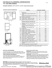
... P Water line location - distance from side 75/16 18.57 N Power supply - distance from bottom 11/4 3.17 O Drain hose - distance from side 349/64 9.58 M Drain hose - distance from hinged side of the part code mentioned herein will be a minimum of ice E machine 131⁄4 33.7 to fixed wall - A dedicated circuit is required. Do not use reverse osmosis, follow these instructions. IMPORTANT: Dimensional specifications...
... P Water line location - distance from side 75/16 18.57 N Power supply - distance from bottom 11/4 3.17 O Drain hose - distance from side 349/64 9.58 M Drain hose - distance from hinged side of the part code mentioned herein will be a minimum of ice E machine 131⁄4 33.7 to fixed wall - A dedicated circuit is required. Do not use reverse osmosis, follow these instructions. IMPORTANT: Dimensional specifications...
Specification Sheet
Page 1
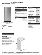
...;/™ © 2020. D200052XXC. Clear Ice Technology Helps produce cubes of Ice Max Ice PrintShield™ Finish (KUIX335HPS only) Filter-Ready Reversible Door Electrical Details Amps 15 or 20 Volts 115/120 Technical Details Ice Maker Type Control Location Ice Capacity Storage (lbs) Drain Pump Installation Option Lighting Type Dimensions Product Dimensions (H x W x D) Depth with Door Open 90° Cutout Dimensions (H x W x D) Reference Material Dimension Guide Install Guide Use & Care Guide Built-In Interior Up Front 25...
...;/™ © 2020. D200052XXC. Clear Ice Technology Helps produce cubes of Ice Max Ice PrintShield™ Finish (KUIX335HPS only) Filter-Ready Reversible Door Electrical Details Amps 15 or 20 Volts 115/120 Technical Details Ice Maker Type Control Location Ice Capacity Storage (lbs) Drain Pump Installation Option Lighting Type Dimensions Product Dimensions (H x W x D) Depth with Door Open 90° Cutout Dimensions (H x W x D) Reference Material Dimension Guide Install Guide Use & Care Guide Built-In Interior Up Front 25...


