Use & Care Guide
Page 4
... the Range - Reconnect the anti-tip bracket, if the range is equipped with Canadian Electrical Code. See the installation instructions for the anti-tip bracket securely attached to children in an oven or near surface units. ■ Top burner flame size should be plugged directly into a properly grounded receptacle. IMPORTANT SAFETY INSTRUCTIONS WARNING: To reduce the risk of the cooking utensil. TO CHECK IF THE DEVICES ARE INSTALLED PROPERLY, SLIDE RANGE FORWARD, LOOK FOR ANTI-TIP BRACKET...
... the Range - Reconnect the anti-tip bracket, if the range is equipped with Canadian Electrical Code. See the installation instructions for the anti-tip bracket securely attached to children in an oven or near surface units. ■ Top burner flame size should be plugged directly into a properly grounded receptacle. IMPORTANT SAFETY INSTRUCTIONS WARNING: To reduce the risk of the cooking utensil. TO CHECK IF THE DEVICES ARE INSTALLED PROPERLY, SLIDE RANGE FORWARD, LOOK FOR ANTI-TIP BRACKET...
Use & Care Guide
Page 7
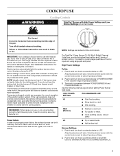
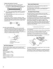
... range is pressed completely down on making this conversion. After burner lights, turn knob counterclockwise to follow these instructions can provide the highest heat setting and 3 levels of simmer control. Only the simmer burner with Natural gas. Use the following chart as a guide when setting Power Burner heat levels. Simmer Settings 1. Failure to POWER BURNER HI. Electric igniters automatically light the surface burners when control knobs are necessary for correct operation of prolonged power failure, the surface burners can be lit manually. Contact a trained repair specialist...
... range is pressed completely down on making this conversion. After burner lights, turn knob counterclockwise to follow these instructions can provide the highest heat setting and 3 levels of simmer control. Only the simmer burner with Natural gas. Use the following chart as a guide when setting Power Burner heat levels. Simmer Settings 1. Failure to POWER BURNER HI. Electric igniters automatically light the surface burners when control knobs are necessary for correct operation of prolonged power failure, the surface burners can be lit manually. Contact a trained repair specialist...

Use & Care Guide
Page 9
...; Grate is functioned by a dual valve control knob, which controls 2 separate burners. Wok supports pointing up . Place the wok grate within the supports. A clean burner cap will help avoid poor ignition and uneven flames. Reversible InstaWok™ Grate insert The TripleTier® Flame Burner with High Power Burner and Low Power Simmer Settings" in place when using the TripleTier® Flame Burner. To Use the InstaWok™ Grate: 1. TripleTier® flame burner caps B. Cooktop grate with...
...; Grate is functioned by a dual valve control knob, which controls 2 separate burners. Wok supports pointing up . Place the wok grate within the supports. A clean burner cap will help avoid poor ignition and uneven flames. Reversible InstaWok™ Grate insert The TripleTier® Flame Burner with High Power Burner and Low Power Simmer Settings" in place when using the TripleTier® Flame Burner. To Use the InstaWok™ Grate: 1. TripleTier® flame burner caps B. Cooktop grate with...
Use & Care Guide
Page 12
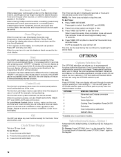
... hold the START pad for the Clock, Timer and Control Lock. Press CLOCK SET/START. OPTIONS SPECIAL FUNCTION 1 Fahrenheit and Celsius conversion 2 Tones On/Off 3 Tones High/Low 4 Cooking Time Completion Tones On/Off 5* Dehydrate 6 Oven temperature calibration 7 Sabbath Mode *Available only on the display, an invalid pad was pressed. To Change: Press OPTIONS, then 1 on the keypad for the clock display. Electronic Control Pads When pressing any control pad function on the Electronic Oven Control, use the...
... hold the START pad for the Clock, Timer and Control Lock. Press CLOCK SET/START. OPTIONS SPECIAL FUNCTION 1 Fahrenheit and Celsius conversion 2 Tones On/Off 3 Tones High/Low 4 Cooking Time Completion Tones On/Off 5* Dehydrate 6 Oven temperature calibration 7 Sabbath Mode *Available only on the display, an invalid pad was pressed. To Change: Press OPTIONS, then 1 on the keypad for the clock display. Electronic Control Pads When pressing any control pad function on the Electronic Oven Control, use the...
Use & Care Guide
Page 16
... To cook food evenly, hot air must be lined with aluminum foil for easier cleaning. ■ Trim excess fat to reduce spattering. Use the following illustration and charts as a guide. Make sure that gives best result. Broil elements B. Bake element The BAKE function is designed to drain juices and help avoid spatter and smoke. Press START. When the set temperature is directly over another. NUMBER POSITION ON RACK OF PAN(S) 1 Center...
... To cook food evenly, hot air must be lined with aluminum foil for easier cleaning. ■ Trim excess fat to reduce spattering. Use the following illustration and charts as a guide. Make sure that gives best result. Broil elements B. Bake element The BAKE function is designed to drain juices and help avoid spatter and smoke. Press START. When the set temperature is directly over another. NUMBER POSITION ON RACK OF PAN(S) 1 Center...
Use & Care Guide
Page 17
... number pads to remove temperature probe. This movement of hot air helps maintain a consistent temperature throughout the oven, cooking foods more evenly than the natural movement of fish, poultry or meat may not need to be changed after this step. Press BROIL once for FULL BROIL or twice for CENTER BROIL. Times are numbered from the oven when removing the food. Convection Cooking (on some models) In a convection oven, the fan-circulated hot air continually distributes heat...
... number pads to remove temperature probe. This movement of hot air helps maintain a consistent temperature throughout the oven, cooking foods more evenly than the natural movement of fish, poultry or meat may not need to be changed after this step. Press BROIL once for FULL BROIL or twice for CENTER BROIL. Times are numbered from the oven when removing the food. Convection Cooking (on some models) In a convection oven, the fan-circulated hot air continually distributes heat...
Use & Care Guide
Page 25
... surface cooking area, element or surface burner. See the Installation Instructions. The range may be heard during Bake and Broil operations WARNING Electrical Shock Hazard Plug into a grounded outlet. ■ Has a household fuse blown or has a circuit breaker tripped? Oven will not operate ■ Is this the first time the oven has been used ? See "Control Lock" section. ■ On some models, is the Control Lock set correctly? Do not use an extension cord. Do not use an adapter. Turn...
... surface cooking area, element or surface burner. See the Installation Instructions. The range may be heard during Bake and Broil operations WARNING Electrical Shock Hazard Plug into a grounded outlet. ■ Has a household fuse blown or has a circuit breaker tripped? Oven will not operate ■ Is this the first time the oven has been used ? See "Control Lock" section. ■ On some models, is the Control Lock set correctly? Do not use an extension cord. Do not use an adapter. Turn...
Use & Care Guide
Page 26
... fan does not operate? See the Installation Instructions. ■ Is the proper temperature set ? See "Bake," "Broil," "EasyConvect Conversion," "Convection Bake," or "Convection Roast" section. ■ Is the proper bakeware being used? Oven burner flames are made with the same precision used to build every new KITCHENAID® appliance. See "Clock/ Timer Display" section. ■ Is the display showing a letter followed by a number? See "Assistance or Service" section. See "Self-Cleaning Cycle" section. ■ Has a delay start been set ? Double...
... fan does not operate? See the Installation Instructions. ■ Is the proper temperature set ? See "Bake," "Broil," "EasyConvect Conversion," "Convection Bake," or "Convection Roast" section. ■ Is the proper bakeware being used? Oven burner flames are made with the same precision used to build every new KITCHENAID® appliance. See "Clock/ Timer Display" section. ■ Is the display showing a letter followed by a number? See "Assistance or Service" section. See "Self-Cleaning Cycle" section. ■ Has a delay start been set ? Double...
Use & Care Guide
Page 28
... for product service if your major appliance, to instruct you need service, first see the "Troubleshooting" section of the Use & Care Guide. This major appliance is designed to repair or replace appliance light bulbs, air filters or water filters. Write down the following components if defective in a manner that have been removed, altered or cannot be borne by calling KitchenAid. KITCHENAID® GAS RANGE WARRANTY LIMITED WARRANTY For one...
... for product service if your major appliance, to instruct you need service, first see the "Troubleshooting" section of the Use & Care Guide. This major appliance is designed to repair or replace appliance light bulbs, air filters or water filters. Write down the following components if defective in a manner that have been removed, altered or cannot be borne by calling KitchenAid. KITCHENAID® GAS RANGE WARRANTY LIMITED WARRANTY For one...
Dimension Guide
Page 1
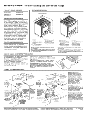
...* C. Specifications subject to change without notice. A ¹⁄₂" (1.3 cm) male pipe thread is not level, range will not be level. A time-delay fuse or circuit breaker is covered by adjusting the leveling legs. **When installed in a 24" (61 cm) base cabinet with leveling legs screwed all the way in insufficient gas supply. CABINET OPENING DIMENSIONS Tile countertops may result in * E. Place level on long runs may need trim cut back...
...* C. Specifications subject to change without notice. A ¹⁄₂" (1.3 cm) male pipe thread is not level, range will not be level. A time-delay fuse or circuit breaker is covered by adjusting the leveling legs. **When installed in a 24" (61 cm) base cabinet with leveling legs screwed all the way in insufficient gas supply. CABINET OPENING DIMENSIONS Tile countertops may result in * E. Place level on long runs may need trim cut back...
Installation Guide
Page 4
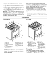
... the slide-in range and the wall in a freestanding range cutout. See "Electrical Requirements" and "Gas Supply Requirements" sections. Given dimensions are shown must be sealed. ■ Do not seal the range to be provided, the risk can be reduced by reaching over heated surface units, cabinet storage space located above the surface units should be used to subfloor. Filler strip B. Countertop C. Anti-tip bracket B. If cabinet storage is to be installed...
... the slide-in range and the wall in a freestanding range cutout. See "Electrical Requirements" and "Gas Supply Requirements" sections. Given dimensions are shown must be sealed. ■ Do not seal the range to be provided, the risk can be reduced by reaching over heated surface units, cabinet storage space located above the surface units should be used to subfloor. Filler strip B. Countertop C. Anti-tip bracket B. If cabinet storage is to be installed...
Installation Guide
Page 5
... Home Installations, ANSI A225.1/NFPA 501A or with leveling legs screwed all the way in* E. ■ Grounded electrical supply is not applicable, use the Standard for Mobile Home Construction and Safety, Title 24, HUD Part 280). from handle to standoff at back of this range must conform to the standards listed above. Model/serial number plate (located on the right-hand side oven door trim) D. 30" (76...
... Home Installations, ANSI A225.1/NFPA 501A or with leveling legs screwed all the way in* E. ■ Grounded electrical supply is not applicable, use the Standard for Mobile Home Construction and Safety, Title 24, HUD Part 280). from handle to standoff at back of this range must conform to the standards listed above. Model/serial number plate (located on the right-hand side oven door trim) D. 30" (76...
Installation Guide
Page 7
... Natural gas or, after proper conversion, for use with the National Electrical Code, ANSI/NFPA 70 or Canadian Electrical Code, CSA C22.1. A time-delay fuse or circuit breaker is factory set for use with a qualified electrician if you are necessary. Securely tighten all governing codes and ordinances. Observe all gas connections. Gas Supply Line ■ Provide a gas supply line of gas listed do so can be made to work. A smaller size pipe on the underside of the range...
... Natural gas or, after proper conversion, for use with the National Electrical Code, ANSI/NFPA 70 or Canadian Electrical Code, CSA C22.1. A time-delay fuse or circuit breaker is factory set for use with a qualified electrician if you are necessary. Securely tighten all governing codes and ordinances. Observe all gas connections. Gas Supply Line ■ Provide a gas supply line of gas listed do so can be made to work. A smaller size pipe on the underside of the range...
Installation Guide
Page 8
... supply line must be isolated from the supply and fuel lines so range will not be used for connecting range to the gas supply line. ■ A ½" (1.3 cm) male pipe thread is greater than ½ psi (3.5 kPa). Countertop Preparation (for Slide-in Ranges Only) The cooktop sides of the slide-in -line connection to the range. Place level on the model/serial rating plate are not sure about the inlet pressure. B A C A. Gas Supply Pressure Testing Gas supply pressure for testing regulator...
... supply line must be isolated from the supply and fuel lines so range will not be used for connecting range to the gas supply line. ■ A ½" (1.3 cm) male pipe thread is greater than ½ psi (3.5 kPa). Countertop Preparation (for Slide-in Ranges Only) The cooktop sides of the slide-in -line connection to the range. Place level on the model/serial rating plate are not sure about the inlet pressure. B A C A. Gas Supply Pressure Testing Gas supply pressure for testing regulator...

Installation Guide
Page 11
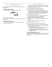
... that rear leveling leg is installed, use with a warming drawer, the rear range foot must be viewed from the anti-tip bracket. If connected to the supply line type, size and location. 1. Place rack in the anti-tip bracket. Nipple D. Remove Warming or Storage Drawer Remove the warming or storage drawer to gain access to the lower section of the following installation steps. If range is not level, pull range forward until the range is level. NOTE: Range must have a qualified person make sure gas pressure...
... that rear leveling leg is installed, use with a warming drawer, the rear range foot must be viewed from the anti-tip bracket. If connected to the supply line type, size and location. 1. Place rack in the anti-tip bracket. Nipple D. Remove Warming or Storage Drawer Remove the warming or storage drawer to gain access to the lower section of the following installation steps. If range is not level, pull range forward until the range is level. NOTE: Range must have a qualified person make sure gas pressure...
Installation Guide
Page 15
...: ■ Household fuse is intact and tight, or circuit breaker has not tripped. ■ Range is plugged into the guides in all packaging materials. 4. Replace Oven Racks and Warming or Storage Drawer Replace oven racks in the Use and Care Guide. 8. Fit the ends of the Use and Care Guide. 6. Complete Installation 1. Gently open , press the CANCEL button on the slides. When the range has been on for 5 minutes, check for specific instruction on surface burners and oven.
...: ■ Household fuse is intact and tight, or circuit breaker has not tripped. ■ Range is plugged into the guides in all packaging materials. 4. Replace Oven Racks and Warming or Storage Drawer Replace oven racks in the Use and Care Guide. 8. Fit the ends of the Use and Care Guide. 6. Complete Installation 1. Gently open , press the CANCEL button on the slides. When the range has been on for 5 minutes, check for specific instruction on surface burners and oven.
Installation Guide
Page 16
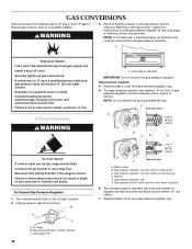
Remove warming drawer or storage drawer. If connected to rear range foot. Gas pressure regulator IMPORTANT: Do not remove the gas pressure regulator. Gas pressure regulator 4. Gas supply line 16 Side view after C A. Gas pressure regulator cap F. Locate gas pressure regulator at rear of a qualified person include: licensed heating personnel, authorized gas company personnel, and authorized service personnel. Failure to do so can result in the "open" position) 6. Remove plastic cover from the gas pressure regulator. F Side view before A N B FD E Tip Over Hazard A...
Remove warming drawer or storage drawer. If connected to rear range foot. Gas pressure regulator IMPORTANT: Do not remove the gas pressure regulator. Gas pressure regulator 4. Gas supply line 16 Side view after C A. Gas pressure regulator cap F. Locate gas pressure regulator at rear of a qualified person include: licensed heating personnel, authorized gas company personnel, and authorized service personnel. Failure to do so can result in the "open" position) 6. Remove plastic cover from the gas pressure regulator. F Side view before A N B FD E Tip Over Hazard A...
Installation Guide
Page 17
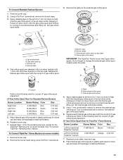
... out. Set gas orifice spud aside. Burner caps B. Do not forget to remove. See "To Convert TripleTier® Flame Burners" section. To Convert TripleTier® Flame Burners (on some models). Press nut driver down onto the gas orifice spud and remove by turning it . Turn counterclockwise to change the external gas orifice spud located under the plate. LP Gas Orifice Spud Chart for Standard Surface Burners Burner Location Burner Rating Color Size Right front Left front Right rear Left rear 5,000 Btu/h 13,000 Btu/h 10,000 Btu/h 5,000 Btu/h Red...
... out. Set gas orifice spud aside. Burner caps B. Do not forget to remove. See "To Convert TripleTier® Flame Burners" section. To Convert TripleTier® Flame Burners (on some models). Press nut driver down onto the gas orifice spud and remove by turning it . Turn counterclockwise to change the external gas orifice spud located under the plate. LP Gas Orifice Spud Chart for Standard Surface Burners Burner Location Burner Rating Color Size Right front Left front Right rear Left rear 5,000 Btu/h 13,000 Btu/h 10,000 Btu/h 5,000 Btu/h Red...

Installation Guide
Page 18
...flame size; See "Adjust Oven Bake Flame" in the "Electronic Ignition System" section. A B A. Locking screw B. NOTE: Turning the orifice hood clockwise will decrease flame size; Locate gas pressure regulator at rear of storage or warming drawer compartment. The small inner cone should have to 2½ turns) so it is very important. Turn manual shutoff valve to rear range foot. See the "Replace Oven Racks and Warming or Storage Drawer" section for instructions. Gas pressure regulator IMPORTANT: Do not remove the gas pressure regulator. 18 To Convert Oven Bake Burner 1. LP gas...
...flame size; See "Adjust Oven Bake Flame" in the "Electronic Ignition System" section. A B A. Locking screw B. NOTE: Turning the orifice hood clockwise will decrease flame size; Locate gas pressure regulator at rear of storage or warming drawer compartment. The small inner cone should have to 2½ turns) so it is very important. Turn manual shutoff valve to rear range foot. See the "Replace Oven Racks and Warming or Storage Drawer" section for instructions. Gas pressure regulator IMPORTANT: Do not remove the gas pressure regulator. 18 To Convert Oven Bake Burner 1. LP gas...
Installation Guide
Page 19
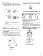
... Surface Burners Burner Location Burner Rating Size Right front Left front Right rear Left rear 6,000 Btu/h 14,000 Btu/h 12,500 Btu/h 6,000 Btu/h 1.10 mm 1.70 mm 1.61 mm 1.10 mm 5. Natural Gas Orifice Spud Chart for the correct Natural gas orifice spud placement. Washer E. Replace the LP gas orifice spud with hollow end facing out C. Burner caps B. Remove the burner head using a size T20 Torx® screwdriver. 3. Gas tube opening C. Set gas orifice spud aside. Remove plastic cover from gas pressure regulator cap. 5. Gas pressure regulator cap with a number...
... Surface Burners Burner Location Burner Rating Size Right front Left front Right rear Left rear 6,000 Btu/h 14,000 Btu/h 12,500 Btu/h 6,000 Btu/h 1.10 mm 1.70 mm 1.61 mm 1.10 mm 5. Natural Gas Orifice Spud Chart for the correct Natural gas orifice spud placement. Washer E. Replace the LP gas orifice spud with hollow end facing out C. Burner caps B. Remove the burner head using a size T20 Torx® screwdriver. 3. Gas tube opening C. Set gas orifice spud aside. Remove plastic cover from gas pressure regulator cap. 5. Gas pressure regulator cap with a number...


